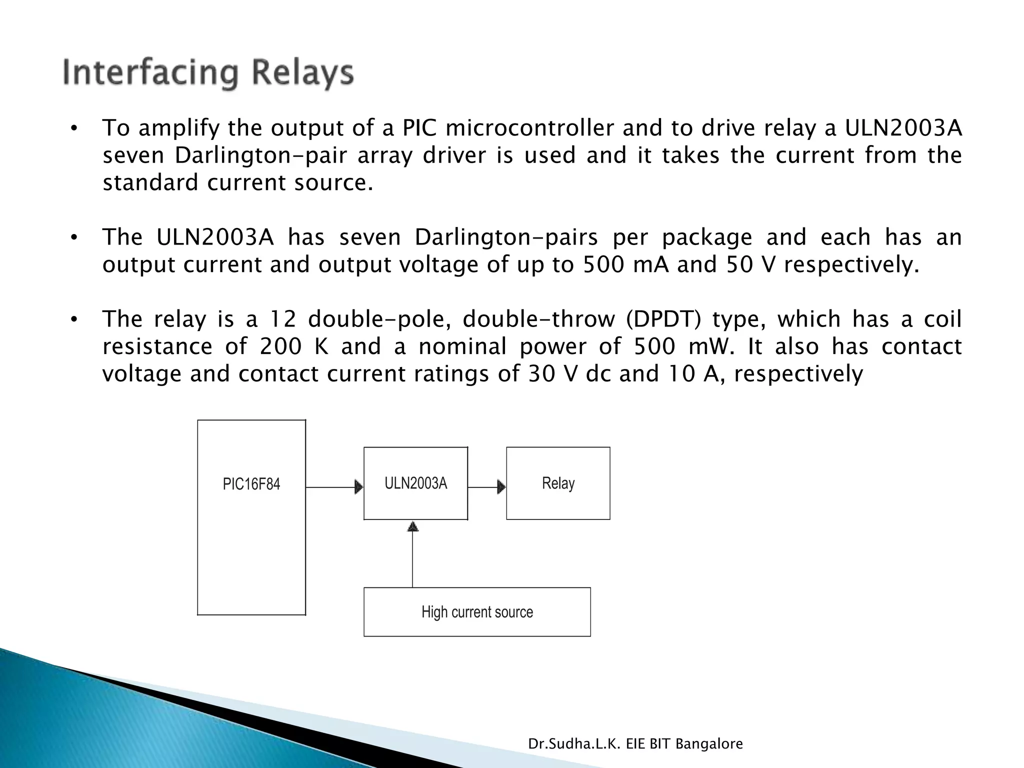
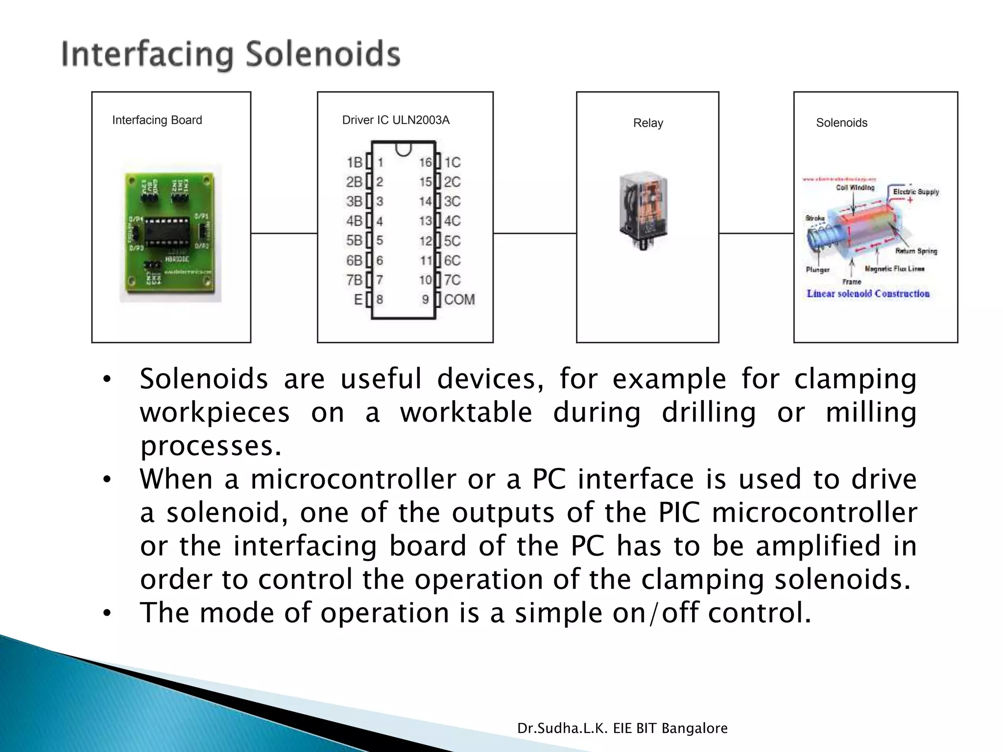
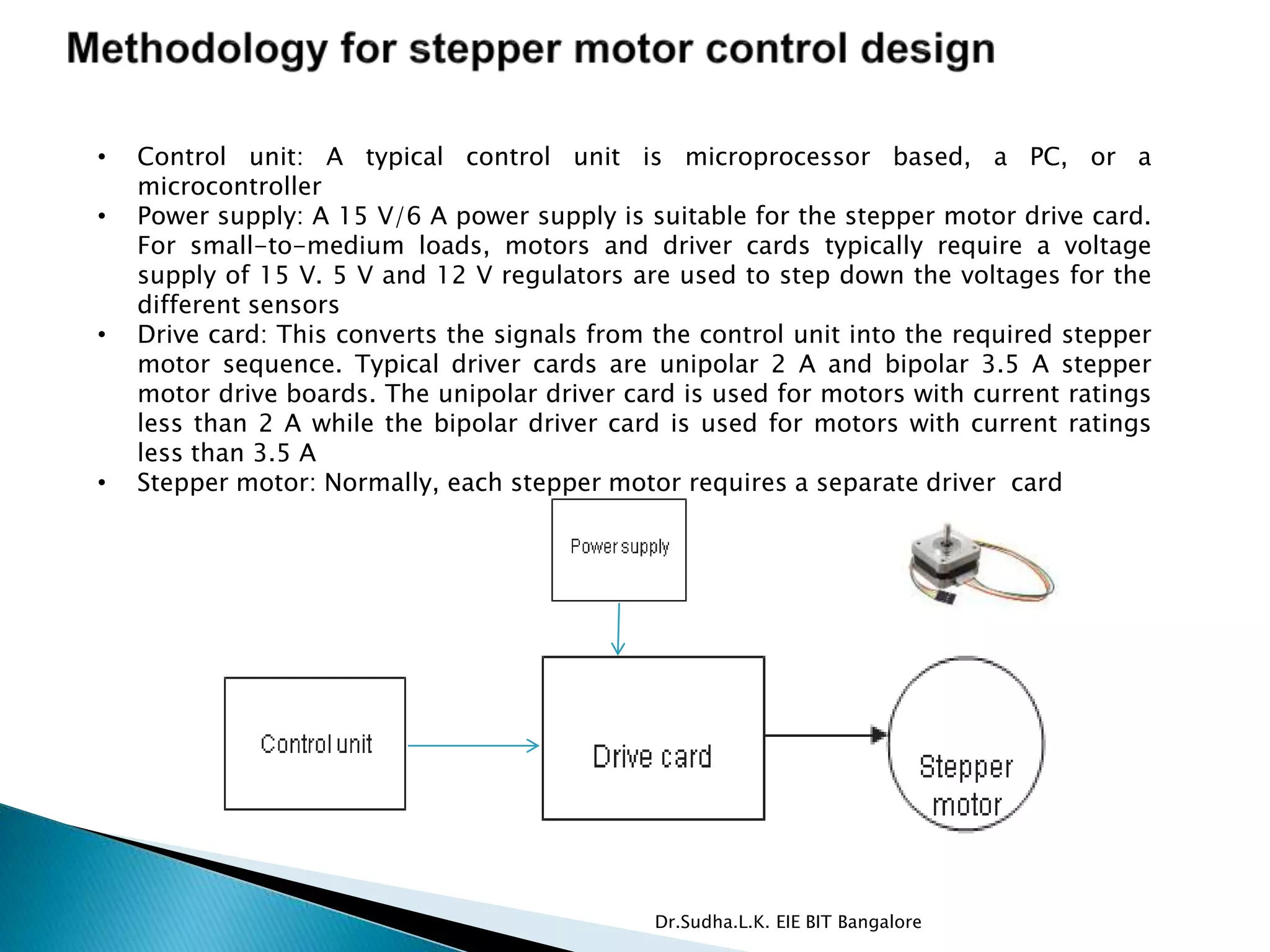
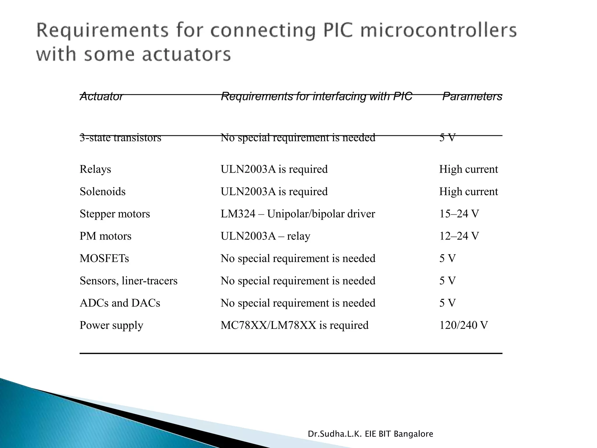
Dr.Sudha.L.K.
Asst. Prof
EIE
BIT Bangalore
Dr.Sudha.L.K. EIE BIT Bangalore
 Interfacing with Three state transistors.
 Interfacing with Relays
 Interfacing with Solenoids
 Interfacing with Stepper motors
 Interfacing with Permanent magnet motors
 Interfacing with Sensors
 Power supplies requirements for a mechatronic
systems
Dr.Sudha.L.K. EIE BIT Bangalore
 Logic families of ICs
◦ TTL based on Bipolar Technology
◦ CMOS based on MOSFET technology
Ex: AND OR NOT NAND NOR latches drivers, decoders
Dr.Sudha.L.K. EIE BIT Bangalore
 74LS373 Octal latch
- 8bit latch, tri state outputs, driving highly capacitive or
low impedance loads, applied as buffer registers, I/O ports,
bidirectional busdrivers, working registers. Old data can be
retained and new data can be entered.
 74LS244 Octal buffer and line driver
- tri state outputs, tristate memory address drivers,
clock drivers, bus oriented receivers and transmitters.
 74LS 138 decoder
- high performance memory systems, data routing
applns, high speed memories, two active low and one active high
enable inputs reduces the number of gates used, an enable input
can be used as a data input for demultiplexing applns.
 74LS00 quad NANAD gate
◦ Quadruple two input positive NAND gate
Dr.Sudha.L.K. EIE BIT Bangalore
High current source
ULN2003APIC16F84 Relay
• To amplify the output of a PIC microcontroller and to drive relay a ULN2003A
seven Darlington-pair array driver is used and it takes the current from the
standard current source.
• The ULN2003A has seven Darlington-pairs per package and each has an
output current and output voltage of up to 500 mA and 50 V respectively.
• The relay is a 12 double-pole, double-throw (DPDT) type, which has a coil
resistance of 200 K and a nominal power of 500 mW. It also has contact
voltage and contact current ratings of 30 V dc and 10 A, respectively
Dr.Sudha.L.K. EIE BIT Bangalore
Interfacing Board Driver IC ULN2003A Relay Solenoids
• Solenoids are useful devices, for example for clamping
workpieces on a worktable during drilling or milling
processes.
• When a microcontroller or a PC interface is used to drive
a solenoid, one of the outputs of the PIC microcontroller
or the interfacing board of the PC has to be amplified in
order to control the operation of the clamping solenoids.
• The mode of operation is a simple on/off control.
Dr.Sudha.L.K. EIE BIT Bangalore
 Hybrid stepper motors (four-phase) are capable of
delivering much higher working torque and
stepping rates (1.8 degrees) than permanent
magnet, servo and wiper motors.
 They also maintain a high detent torque even
when not energized.
 This feature is good for positional integrity.
Commonly used stepper motors are directly
compatible with proprietary stepper motor drive
boards.
Dr.Sudha.L.K. EIE BIT Bangalore
• Control unit: A typical control unit is microprocessor based, a PC, or a
microcontroller
• Power supply: A 15 V/6 A power supply is suitable for the stepper motor drive card.
For small-to-medium loads, motors and driver cards typically require a voltage
supply of 15 V. 5 V and 12 V regulators are used to step down the voltages for the
different sensors
• Drive card: This converts the signals from the control unit into the required stepper
motor sequence. Typical driver cards are unipolar 2 A and bipolar 3.5 A stepper
motor drive boards. The unipolar driver card is used for motors with current ratings
less than 2 A while the bipolar driver card is used for motors with current ratings
less than 3.5 A
• Stepper motor: Normally, each stepper motor requires a separate driver card
Dr.Sudha.L.K. EIE BIT Bangalore
 The motor drive methods used for the control of the hybrid stepper
motors are:
 unipolar stepper motor drive;
 bipolar stepper motor drive.
Dr.Sudha.L.K. EIE BIT Bangalore
 The use of d.c. motors is common in mechatronics
applications. This problem is also encountered when
interfacing a PC with motors or other actuators that draw
heavy current.
 All automotive windshield wiper motors operate at three
distinct speeds in both directions. The usual rotation speed is
40 revolutions per minute. A maximum of 4A d.c is drawn
during startup at 12 V. However, the normal working current
consumption is as low as 1.32 A.
 Two methods of interfacing a PC or microcontrollers with
PM motors are:
◦ use of relay circuits;
◦ use of H-bridge circuits.
Dr.Sudha.L.K. EIE BIT Bangalore
PIC16F84 ULN20003A Relay
High current source
• Block diagram shows how to interface a PIC microcontroller with a
PM motor using a relay.
High current source,PIC16F84,Motor,Relay,ULN2003A
Dr.Sudha.L.K. EIE BIT Bangalore
 H-bridge circuit is a very efficient method because it requires only a single
unipolar power supply.
 Fig. shows a simple H-bridge circuit using pulsed-width modulated (PWM)
controlled voltages consists of four switching transistors.
 A PM motor speed control system that is more compatible with microcon-
trollers. A PWM voltage is applied to a single input, and the motor direction
is controlled with a HIGH/LOW voltage on a second input. Using an H-bridge
circuit is a very efficient method because it requires only a single unipolar
power supply.
Dr.Sudha.L.K. EIE BIT Bangalore
Simplified motor speed control using PWM
Three signals are used for the motor speed control switching
circuit: PWM, DIR (direction) and EN (Enable).
Practical motor speed control using PWM
A more practical motor speed control circuit using PWM, which
can be used to control a range of motors (12–24 V) and a range of
current ratings
Dr.Sudha.L.K. EIE BIT Bangalore
 Circuits employing sensors are easy to implement as the most sensors
operate on 5 V.
 Sensors such as the photodiode/phototransistor pair, the photoreflector
sensor, the infrared sensor and line tracers.
The diode/phototransistor pair
 A diode/phototransistor pair (e.g. OP140/OP550) is useful in designing an
encoder for PM motor speed control.
 A rotating disk with slots is attached to the motor and located between the
diode/phototransistor pair.
 The rotating disk will generate pulses which are then transmitted to a
microcontroller. A diode/ phototransistor pair biasing circuit is shown in.
 The circuit provides a cost-effective means for easy interfacing with a
microcontroller in a mechatronic system.
Dr.Sudha.L.K. EIE BIT Bangalore
 Two photo reflector sensors are used to locate an object.
 These sensors are useful when placed on the tips of a pick-and-place
gripper, to give accurate positioning.
 While the pick-and-place robot is approaching the object, the sensor output
is high indicating that the object is in front if it.
 The distance between the sides of the gripper is bigger than the length of the
object to be picked.
 Therefore, only one sensor can go high, or both the photoreflective sensors
stay low. If the left sensor goes high, the robot will rotate left until the sensor
goes low. If the right sensor goes high, the robot will rotate right until the
sensor goes low. When both the sensors are low, it indicates that the object
is in the center of the gripper in readiness for pick up.
Dr.Sudha.L.K. EIE BIT Bangalore
 Common sensors used in mobile robots for detecting
obstacles are the digital Sharp GP2Y0D02YK infrared (IR)
sensor shown in Figure and the analog Sharp IR
GP2Y0A02YK.
 The digital device operates at 5 V and gives out a logic signal
if it detects any object within 0.8 m of its field of view (a thin
streak extending between its emitter and detector).
 This sensor’s behavior is less influenced by the color of the
object since it uses an optical triangle method of
measurement. The analog device outputs analog voltages
proportional to an object’s distance
Dr.Sudha.L.K. EIE BIT Bangalore
 Purpose-built line-tracing sensors, operating at 5 V are available
which can distinguish between white and black surfaces.
 Over a white surface, a logic high signal is produced. The distance
between the sensor and the surface is critical and is typically
between 8 and 12 mm, hence false detection is possible where the
surface may not be flat.
 A useful approach would be to attach a mechanism to the sensor in
order to maintain the distance of the line tracer within the specified
region.
Dr.Sudha.L.K. EIE BIT Bangalore
 The following illustrates an example relating to a PC-based (microcontroller)
CNC drilling machine. The fundamental architecture involves digital signals
fed from the interface card using the output pins that are required to be in
analog form, within a range of 0–5 V. The analog signal is linked to a pulse
width modulator.
 The DAC selected is an AD557. It has a range of 0–2.56 V and is 8-bit. It is
specifically designed for interfacing microprocessor-based applications. The
drill motor speed has a maximum of 2000 rpm.
 Since the DAC produces a maximum of only 2.56 V, an op amp been used to
step up the signal to 5 V. This means each bit corresponds to 7.843
revolutions per minute. This is a very reasonable resolution.
Dr.Sudha.L.K. EIE BIT Bangalore
Actuator Requirements for interfacing with PIC Parameters
3-state transistors No special requirement is needed 5 V
Relays ULN2003A is required High current
Solenoids ULN2003A is required High current
Stepper motors LM324 – Unipolar/bipolar driver 15–24 V
PM motors ULN2003A – relay 12–24 V
MOSFETs No special requirement is needed 5 V
Sensors, liner-tracers No special requirement is needed 5 V
ADCs and DACs No special requirement is needed 5 V
Power supply MC78XX/LM78XX is required 120/240 V
Dr.Sudha.L.K. EIE BIT Bangalore
 All over the world, electrical energy is available in the form of
alternating current rated between 100–120 V or 240 V.
 The a.c. frequency is 50 Hz. Mechatronic applications deal
with electronics, where smaller ratings of direct current
voltages are required.
 TTL ICs operate on a 5 V d.c. supply, stepper cards operate
on a 12 V d.c. supply, and stepper motors operate on a 15–
24 V d.c. supply.
 Power supply unit has to be used to convert the a.c. voltage
to a d.c. voltage at the 100/120 V or 240 V level, before
stepping down to the level compatible with the ICs
Dr.Sudha.L.K. EIE BIT Bangalore

Module 4

  • 1.
  • 2.
     Interfacing withThree state transistors.  Interfacing with Relays  Interfacing with Solenoids  Interfacing with Stepper motors  Interfacing with Permanent magnet motors  Interfacing with Sensors  Power supplies requirements for a mechatronic systems Dr.Sudha.L.K. EIE BIT Bangalore
  • 3.
     Logic familiesof ICs ◦ TTL based on Bipolar Technology ◦ CMOS based on MOSFET technology Ex: AND OR NOT NAND NOR latches drivers, decoders Dr.Sudha.L.K. EIE BIT Bangalore
  • 4.
     74LS373 Octallatch - 8bit latch, tri state outputs, driving highly capacitive or low impedance loads, applied as buffer registers, I/O ports, bidirectional busdrivers, working registers. Old data can be retained and new data can be entered.  74LS244 Octal buffer and line driver - tri state outputs, tristate memory address drivers, clock drivers, bus oriented receivers and transmitters.  74LS 138 decoder - high performance memory systems, data routing applns, high speed memories, two active low and one active high enable inputs reduces the number of gates used, an enable input can be used as a data input for demultiplexing applns.  74LS00 quad NANAD gate ◦ Quadruple two input positive NAND gate Dr.Sudha.L.K. EIE BIT Bangalore
  • 5.
    High current source ULN2003APIC16F84Relay • To amplify the output of a PIC microcontroller and to drive relay a ULN2003A seven Darlington-pair array driver is used and it takes the current from the standard current source. • The ULN2003A has seven Darlington-pairs per package and each has an output current and output voltage of up to 500 mA and 50 V respectively. • The relay is a 12 double-pole, double-throw (DPDT) type, which has a coil resistance of 200 K and a nominal power of 500 mW. It also has contact voltage and contact current ratings of 30 V dc and 10 A, respectively Dr.Sudha.L.K. EIE BIT Bangalore
  • 6.
    Interfacing Board DriverIC ULN2003A Relay Solenoids • Solenoids are useful devices, for example for clamping workpieces on a worktable during drilling or milling processes. • When a microcontroller or a PC interface is used to drive a solenoid, one of the outputs of the PIC microcontroller or the interfacing board of the PC has to be amplified in order to control the operation of the clamping solenoids. • The mode of operation is a simple on/off control. Dr.Sudha.L.K. EIE BIT Bangalore
  • 7.
     Hybrid steppermotors (four-phase) are capable of delivering much higher working torque and stepping rates (1.8 degrees) than permanent magnet, servo and wiper motors.  They also maintain a high detent torque even when not energized.  This feature is good for positional integrity. Commonly used stepper motors are directly compatible with proprietary stepper motor drive boards. Dr.Sudha.L.K. EIE BIT Bangalore
  • 8.
    • Control unit:A typical control unit is microprocessor based, a PC, or a microcontroller • Power supply: A 15 V/6 A power supply is suitable for the stepper motor drive card. For small-to-medium loads, motors and driver cards typically require a voltage supply of 15 V. 5 V and 12 V regulators are used to step down the voltages for the different sensors • Drive card: This converts the signals from the control unit into the required stepper motor sequence. Typical driver cards are unipolar 2 A and bipolar 3.5 A stepper motor drive boards. The unipolar driver card is used for motors with current ratings less than 2 A while the bipolar driver card is used for motors with current ratings less than 3.5 A • Stepper motor: Normally, each stepper motor requires a separate driver card Dr.Sudha.L.K. EIE BIT Bangalore
  • 9.
     The motordrive methods used for the control of the hybrid stepper motors are:  unipolar stepper motor drive;  bipolar stepper motor drive. Dr.Sudha.L.K. EIE BIT Bangalore
  • 10.
     The useof d.c. motors is common in mechatronics applications. This problem is also encountered when interfacing a PC with motors or other actuators that draw heavy current.  All automotive windshield wiper motors operate at three distinct speeds in both directions. The usual rotation speed is 40 revolutions per minute. A maximum of 4A d.c is drawn during startup at 12 V. However, the normal working current consumption is as low as 1.32 A.  Two methods of interfacing a PC or microcontrollers with PM motors are: ◦ use of relay circuits; ◦ use of H-bridge circuits. Dr.Sudha.L.K. EIE BIT Bangalore
  • 11.
    PIC16F84 ULN20003A Relay Highcurrent source • Block diagram shows how to interface a PIC microcontroller with a PM motor using a relay. High current source,PIC16F84,Motor,Relay,ULN2003A Dr.Sudha.L.K. EIE BIT Bangalore
  • 12.
     H-bridge circuitis a very efficient method because it requires only a single unipolar power supply.  Fig. shows a simple H-bridge circuit using pulsed-width modulated (PWM) controlled voltages consists of four switching transistors.  A PM motor speed control system that is more compatible with microcon- trollers. A PWM voltage is applied to a single input, and the motor direction is controlled with a HIGH/LOW voltage on a second input. Using an H-bridge circuit is a very efficient method because it requires only a single unipolar power supply. Dr.Sudha.L.K. EIE BIT Bangalore
  • 13.
    Simplified motor speedcontrol using PWM Three signals are used for the motor speed control switching circuit: PWM, DIR (direction) and EN (Enable). Practical motor speed control using PWM A more practical motor speed control circuit using PWM, which can be used to control a range of motors (12–24 V) and a range of current ratings Dr.Sudha.L.K. EIE BIT Bangalore
  • 14.
     Circuits employingsensors are easy to implement as the most sensors operate on 5 V.  Sensors such as the photodiode/phototransistor pair, the photoreflector sensor, the infrared sensor and line tracers. The diode/phototransistor pair  A diode/phototransistor pair (e.g. OP140/OP550) is useful in designing an encoder for PM motor speed control.  A rotating disk with slots is attached to the motor and located between the diode/phototransistor pair.  The rotating disk will generate pulses which are then transmitted to a microcontroller. A diode/ phototransistor pair biasing circuit is shown in.  The circuit provides a cost-effective means for easy interfacing with a microcontroller in a mechatronic system. Dr.Sudha.L.K. EIE BIT Bangalore
  • 15.
     Two photoreflector sensors are used to locate an object.  These sensors are useful when placed on the tips of a pick-and-place gripper, to give accurate positioning.  While the pick-and-place robot is approaching the object, the sensor output is high indicating that the object is in front if it.  The distance between the sides of the gripper is bigger than the length of the object to be picked.  Therefore, only one sensor can go high, or both the photoreflective sensors stay low. If the left sensor goes high, the robot will rotate left until the sensor goes low. If the right sensor goes high, the robot will rotate right until the sensor goes low. When both the sensors are low, it indicates that the object is in the center of the gripper in readiness for pick up. Dr.Sudha.L.K. EIE BIT Bangalore
  • 16.
     Common sensorsused in mobile robots for detecting obstacles are the digital Sharp GP2Y0D02YK infrared (IR) sensor shown in Figure and the analog Sharp IR GP2Y0A02YK.  The digital device operates at 5 V and gives out a logic signal if it detects any object within 0.8 m of its field of view (a thin streak extending between its emitter and detector).  This sensor’s behavior is less influenced by the color of the object since it uses an optical triangle method of measurement. The analog device outputs analog voltages proportional to an object’s distance Dr.Sudha.L.K. EIE BIT Bangalore
  • 17.
     Purpose-built line-tracingsensors, operating at 5 V are available which can distinguish between white and black surfaces.  Over a white surface, a logic high signal is produced. The distance between the sensor and the surface is critical and is typically between 8 and 12 mm, hence false detection is possible where the surface may not be flat.  A useful approach would be to attach a mechanism to the sensor in order to maintain the distance of the line tracer within the specified region. Dr.Sudha.L.K. EIE BIT Bangalore
  • 18.
     The followingillustrates an example relating to a PC-based (microcontroller) CNC drilling machine. The fundamental architecture involves digital signals fed from the interface card using the output pins that are required to be in analog form, within a range of 0–5 V. The analog signal is linked to a pulse width modulator.  The DAC selected is an AD557. It has a range of 0–2.56 V and is 8-bit. It is specifically designed for interfacing microprocessor-based applications. The drill motor speed has a maximum of 2000 rpm.  Since the DAC produces a maximum of only 2.56 V, an op amp been used to step up the signal to 5 V. This means each bit corresponds to 7.843 revolutions per minute. This is a very reasonable resolution. Dr.Sudha.L.K. EIE BIT Bangalore
  • 19.
    Actuator Requirements forinterfacing with PIC Parameters 3-state transistors No special requirement is needed 5 V Relays ULN2003A is required High current Solenoids ULN2003A is required High current Stepper motors LM324 – Unipolar/bipolar driver 15–24 V PM motors ULN2003A – relay 12–24 V MOSFETs No special requirement is needed 5 V Sensors, liner-tracers No special requirement is needed 5 V ADCs and DACs No special requirement is needed 5 V Power supply MC78XX/LM78XX is required 120/240 V Dr.Sudha.L.K. EIE BIT Bangalore
  • 20.
     All overthe world, electrical energy is available in the form of alternating current rated between 100–120 V or 240 V.  The a.c. frequency is 50 Hz. Mechatronic applications deal with electronics, where smaller ratings of direct current voltages are required.  TTL ICs operate on a 5 V d.c. supply, stepper cards operate on a 12 V d.c. supply, and stepper motors operate on a 15– 24 V d.c. supply.  Power supply unit has to be used to convert the a.c. voltage to a d.c. voltage at the 100/120 V or 240 V level, before stepping down to the level compatible with the ICs Dr.Sudha.L.K. EIE BIT Bangalore
  • 21.