Downloaded 674 times
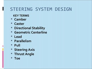
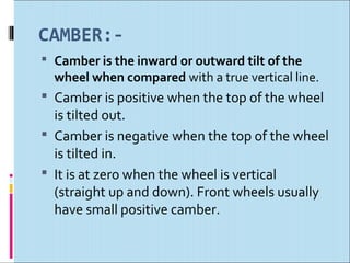
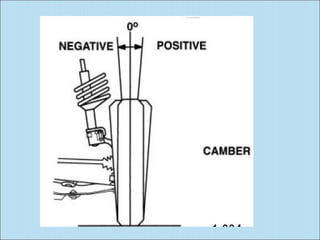
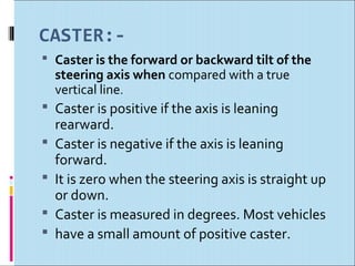
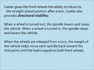
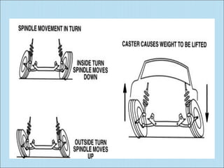
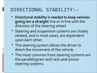
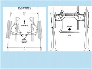
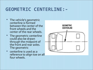
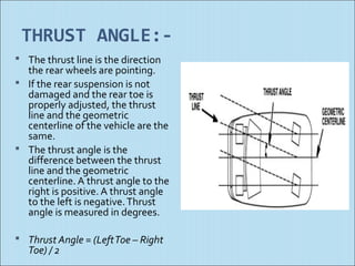
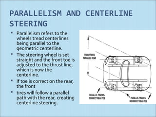
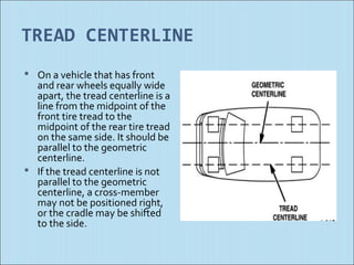
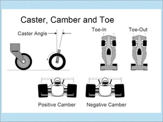
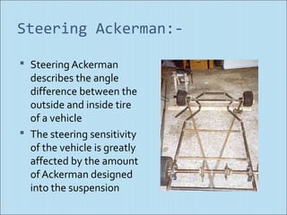
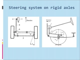
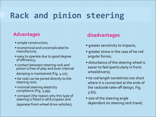
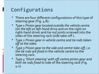
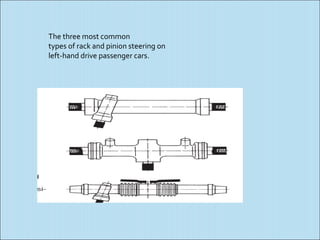
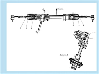
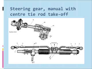
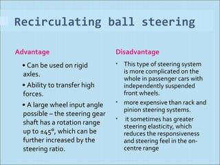


This document discusses key terms and concepts related to steering system design, including camber, caster, directional stability, geometric centerline, toe, parallelism, and Ackerman steering. It provides definitions and explanations of these terms. For example, it explains that caster provides directional stability and the ability of wheels to return to the straight ahead position after a turn. It also discusses various steering system types like rack and pinion steering and their advantages and disadvantages.


