Downloaded 291 times


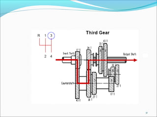
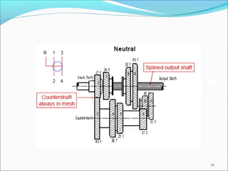
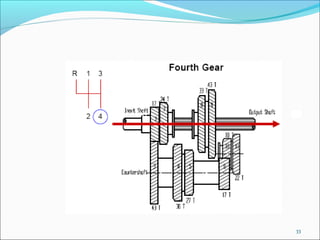

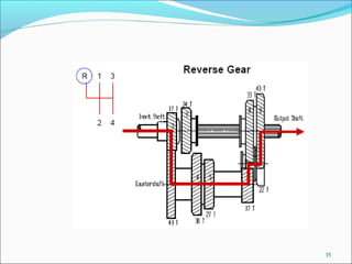
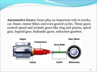
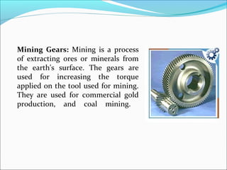
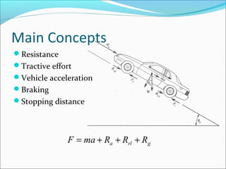
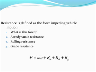
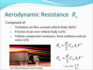
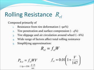
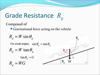
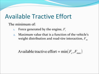
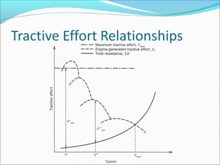

Gears play an important role in transmitting power in vehicles and machinery. They reduce speed and increase torque in gear trains and gear boxes. The document discusses different types of gears like spur gears, helical gears, bevel gears, and planetary (epicyclic) gears. It also explains how gears are used in automobiles, ships, wind turbines, power stations, mining equipment, and other applications to change rotational motion and speed. Resistance to vehicle motion from aerodynamic drag, rolling friction, and road grades must be overcome through the available tractive effort from the vehicle's engine and tires.


