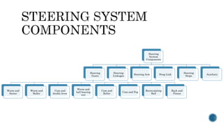
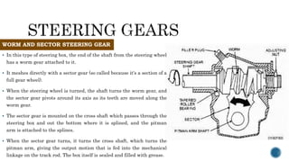
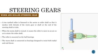
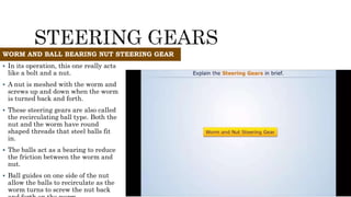
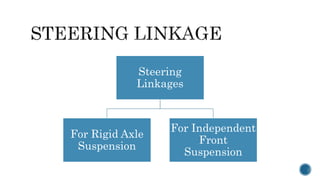
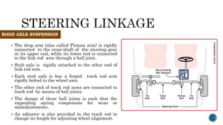
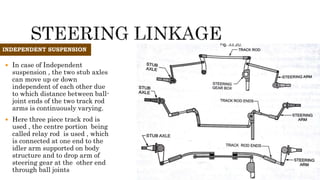
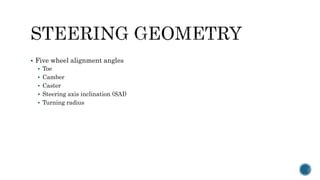
STEERING SYSTEM
 Steering is the term applied to the collection of components, linkages, etc. which
will allow a vehicle to follow the desired path.
 An automobile is steered with the help of steering gears and linkages, which
transfer the motion of the hand operated steering wheel to the pivoted front wheel
hubs via steering column.
 The other parts that are used for steering a vehicle are steering wheel pads,
steering shafts, steering boxes, steering arms and steering stabilizers.
•Control of front wheel (sometimes
rear wheel) direction.
•Maintain correct amount of effort
needed to turn the wheels.
•Transmit road feel (slight steering
wheel pull caused by the road surface)
to the drivers hand.
•Absorb most of the shock going to the
steering wheel as the tire hits holes
and bumps in the road.
•Allow for suspension action.
Steering
System
Components
Steering
Gears
Worm and
Sector
Worm and
Roller
Cam and
double lever
Worm and
ball bearing
nut
Cam and
Roller
Cam and Peg
Recirculating
Ball
Rack and
Pinion
Steering
Linkages
Steering Arm Drag Link
Steering
Stops
Auxiliary
 In this type of steering box, the end of the shaft from the steering wheel
has a worm gear attached to it.
 It meshes directly with a sector gear (so called because it's a section of a
full gear wheel).
 When the steering wheel is turned, the shaft turns the worm gear, and
the sector gear pivots around its axis as its teeth are moved along the
worm gear.
 The sector gear is mounted on the cross shaft which passes through the
steering box and out the bottom where it is splined, and the pitman
arm is attached to the splines.
 When the sector gear turns, it turns the cross shaft, which turns the
pitman arm, giving the output motion that is fed into the mechanical
linkage on the track rod. The box itself is sealed and filled with grease.
WORM AND SECTOR STEERING GEAR
 A two toothed roller is fastened to the sector or roller shaft so that it
meshes with threads of the worm gear or shaft at the end of the
steering shaft or tube.
 When the worm shaft is turned, it causes the roller to move in an arc so
as to rotate the roller shaft.
 The roller is mounted on the ball bearings
 The worm shaft is connected on bearings designed to resist both radial
and end thrust.
WORM AND ROLLER STEERING GEAR
 In its operation, this one really acts
like a bolt and a nut.
 A nut is meshed with the worm and
screws up and down when the worm
is turned back and forth.
 These steering gears are also called
the recirculating ball type. Both the
nut and the worm have round
shaped threads that steel balls fit
in.
 The balls act as a bearing to reduce
the friction between the worm and
nut.
 Ball guides on one side of the nut
allow the balls to recirculate as the
worm turns to screw the nut back
WORM AND BALL BEARING NUT STEERING GEAR
RECIRCULATING BALL STEERING GEAR
RACK & PINION STEERING GEAR
Steering
Linkages
For Rigid Axle
Suspension
For Independent
Front
Suspension
 The drop arm (also called Pitman arm) is rigidly
connected to the cross-shaft of the steering gear
at its upper end, while its lower end is connected
to the link rod arm through a ball joint.
 Stub axle is rigidly attached to the other end of
link rod arm.
 Each stub axle is has a forged track rod arm
rigidly bolted to the wheel axis.
 The other end of track rod arms are connected to
track rod by means of ball joints.
 The design of these ball joints is such that the
expanding spring compensate for wear or
maladjustments.
 An adjuster is also provided in the track rod to
change its length for adjusting wheel alignment.
RIGID AXLE SUSPENSION
 In case of Independent
suspension , the two stub axles
can move up or down
independent of each other due
to which distance between ball-
joint ends of the two track rod
arms is continuously varying.
 Here three piece track rod is
used , the centre portion being
called relay rod is used , which
is connected at one end to the
idler arm supported on body
structure and to drop arm of
steering gear at the other end
through ball joints
INDEPENDENT SUSPENSION
 The
ELECTRIC POWER STEERING
HYDRAULIC POWER STEERING
 Electro-hydraulic power steering
systems, sometimes abbreviated
EHPS, and also sometimes
called "hybrid" systems, use the
same hydraulic assist
technology as standard systems,
but the hydraulic pressure is
provided by a pump driven by
an electric motor instead of
being belt-driven by the engine.
 By providing power assist via
hydraulic pressure, this system
delivers a naturally smooth
steering feel and, thanks to the
flexibility of control allowed by
electric power, offers more
precise steering power
characteristics. It also improves
fuel economy since the electric
powered pump operates only
when steering assist is needed
ELECTRO-HYDRAULIC POWER STEERING
 The perfect steering is achieved
when all the four wheels are
rolling perfectly under all
conditions of running.
 While taking turns ,the condition
of perfect rolling is satisfied if the
axes of the front wheels when
produced meet the rear wheel axis
at one point.
 Then this point is the
instantaneous centre of the
vehicle.
 In order to avoid skidding(slipping of the
wheels of sideways),the two front wheels
must turn about the same instantaneous
centre which lies on the axis of the back
wheels.
 It is seen that the inside wheel is
required to turn through a greater angle
than the outer wheel.
 The larger is the steering angle, the
smaller is the turning circle.
 The diameter of the smallest circle which
the outer front wheel of the car can
traverse and obtained when the wheels
are at their extreme positions is known
as the turning circle.
A C
E F
B
a
b
I
f q
cot
cot
cot cot
EI EF FI a FI
AE AE b
FI FI
CF b
a FI FI a
b b b
q
f
q f
 
  
 

    
 This is an exact steering gear mechanism. This mechanism fulfils
the above steering condition. But due to presence of more sliding
members, the wear will be increased and this eliminates the
accuracy.
 It is much simpler than Davis
mechanism.
 Difference between Davis and Ackerman
mechanism:
 The whole mechanism is on back of the
front wheels , whereas in Davis ,it is in
front of the wheels.
 It consists of turning pairs, whereas in
Davis, it consists of sliding pairs.
 When the vehicle moves along straight
path, the longer links AB and CD are
parallel and the shorter links BC and AD
are equally inclined to the longitudinal
axis of the vehicle.
 When the vehicle moves left, the position
 Five wheel alignment angles
 Toe
 Camber
 Caster
 Steering axis inclination (SAI)
 Turning radius
Toe
• Comparison of distances between fronts and
rears of a pair of tires
• Alignment angle most responsible for tire wear
• Toe-in: tires closer together at the front
• Every 1/16" of toe-in results in 11 feet per mile
scuff
• Tires move sideways for 11 feet out of every mile
• Toe-out: tires further apart at the front
Camber
 Camber: inward or outward tilt of tire at top
 Adjustable on most vehicles
 Positive camber: tire tilts out
 Negative camber: tire tilts in
 Inside and outside edges of tread on cambered tire
have different radii
 Rotate at different speeds
 Camber angle
 Controlled by position of control arms or struts
 Camber roll: tire tends to roll in a circle
Caster
 Caster: forward or rearward tilt of the spindle support arm
 Positive caster: top tilted to the rear
o Lead point in front of true vertical
 Negative caster: steering axis tilts forward
o Moving the point of load behind the wheel
 Sometimes adjustable on front wheels
 Front wheels have different caster settings
o Vehicle will pull toward the side with the most negative caster
Steering Axis Inclination
 Amount the spindle support arm leans in at top
 Not a tire wearing angle
 Three functions
 After a turn, SAI helps vehicle return to straight
 SAI keeps vehicle going straight down the road
 Allows car to have less positive caster
 Included angle
 Combination of SAI and camber
 Some cars with large SAI wear outsides of tires
Steering Axis Inclination
 Factor of steering axis inclination
 Pivot point for front tire’s footprint
 Distance at the road surface between centerline
of true vertical and steering axis pivot centerline
 More scrub radius makes it harder to steer
 Positive camber reduces scrub radius
 Causes of incorrect scrub radius
 Lower profile tires and offset wheel rims
 Tires and wheels too tall installed on RWD vehicle
 Bent front suspension member
 Damage to frame at cross member

STEERING SYSTEM.pptx

  • 2.
    STEERING SYSTEM  Steeringis the term applied to the collection of components, linkages, etc. which will allow a vehicle to follow the desired path.  An automobile is steered with the help of steering gears and linkages, which transfer the motion of the hand operated steering wheel to the pivoted front wheel hubs via steering column.  The other parts that are used for steering a vehicle are steering wheel pads, steering shafts, steering boxes, steering arms and steering stabilizers.
  • 3.
    •Control of frontwheel (sometimes rear wheel) direction. •Maintain correct amount of effort needed to turn the wheels. •Transmit road feel (slight steering wheel pull caused by the road surface) to the drivers hand. •Absorb most of the shock going to the steering wheel as the tire hits holes and bumps in the road. •Allow for suspension action.
  • 4.
    Steering System Components Steering Gears Worm and Sector Worm and Roller Camand double lever Worm and ball bearing nut Cam and Roller Cam and Peg Recirculating Ball Rack and Pinion Steering Linkages Steering Arm Drag Link Steering Stops Auxiliary
  • 5.
     In thistype of steering box, the end of the shaft from the steering wheel has a worm gear attached to it.  It meshes directly with a sector gear (so called because it's a section of a full gear wheel).  When the steering wheel is turned, the shaft turns the worm gear, and the sector gear pivots around its axis as its teeth are moved along the worm gear.  The sector gear is mounted on the cross shaft which passes through the steering box and out the bottom where it is splined, and the pitman arm is attached to the splines.  When the sector gear turns, it turns the cross shaft, which turns the pitman arm, giving the output motion that is fed into the mechanical linkage on the track rod. The box itself is sealed and filled with grease. WORM AND SECTOR STEERING GEAR
  • 6.
     A twotoothed roller is fastened to the sector or roller shaft so that it meshes with threads of the worm gear or shaft at the end of the steering shaft or tube.  When the worm shaft is turned, it causes the roller to move in an arc so as to rotate the roller shaft.  The roller is mounted on the ball bearings  The worm shaft is connected on bearings designed to resist both radial and end thrust. WORM AND ROLLER STEERING GEAR
  • 7.
     In itsoperation, this one really acts like a bolt and a nut.  A nut is meshed with the worm and screws up and down when the worm is turned back and forth.  These steering gears are also called the recirculating ball type. Both the nut and the worm have round shaped threads that steel balls fit in.  The balls act as a bearing to reduce the friction between the worm and nut.  Ball guides on one side of the nut allow the balls to recirculate as the worm turns to screw the nut back WORM AND BALL BEARING NUT STEERING GEAR
  • 8.
  • 9.
    RACK & PINIONSTEERING GEAR
  • 10.
  • 11.
     The droparm (also called Pitman arm) is rigidly connected to the cross-shaft of the steering gear at its upper end, while its lower end is connected to the link rod arm through a ball joint.  Stub axle is rigidly attached to the other end of link rod arm.  Each stub axle is has a forged track rod arm rigidly bolted to the wheel axis.  The other end of track rod arms are connected to track rod by means of ball joints.  The design of these ball joints is such that the expanding spring compensate for wear or maladjustments.  An adjuster is also provided in the track rod to change its length for adjusting wheel alignment. RIGID AXLE SUSPENSION
  • 12.
     In caseof Independent suspension , the two stub axles can move up or down independent of each other due to which distance between ball- joint ends of the two track rod arms is continuously varying.  Here three piece track rod is used , the centre portion being called relay rod is used , which is connected at one end to the idler arm supported on body structure and to drop arm of steering gear at the other end through ball joints INDEPENDENT SUSPENSION
  • 13.
  • 14.
  • 15.
  • 16.
     Electro-hydraulic powersteering systems, sometimes abbreviated EHPS, and also sometimes called "hybrid" systems, use the same hydraulic assist technology as standard systems, but the hydraulic pressure is provided by a pump driven by an electric motor instead of being belt-driven by the engine.  By providing power assist via hydraulic pressure, this system delivers a naturally smooth steering feel and, thanks to the flexibility of control allowed by electric power, offers more precise steering power characteristics. It also improves fuel economy since the electric powered pump operates only when steering assist is needed ELECTRO-HYDRAULIC POWER STEERING
  • 17.
     The perfectsteering is achieved when all the four wheels are rolling perfectly under all conditions of running.  While taking turns ,the condition of perfect rolling is satisfied if the axes of the front wheels when produced meet the rear wheel axis at one point.  Then this point is the instantaneous centre of the vehicle.
  • 18.
     In orderto avoid skidding(slipping of the wheels of sideways),the two front wheels must turn about the same instantaneous centre which lies on the axis of the back wheels.  It is seen that the inside wheel is required to turn through a greater angle than the outer wheel.  The larger is the steering angle, the smaller is the turning circle.  The diameter of the smallest circle which the outer front wheel of the car can traverse and obtained when the wheels are at their extreme positions is known as the turning circle.
  • 19.
    A C E F B a b I fq cot cot cot cot EI EF FI a FI AE AE b FI FI CF b a FI FI a b b b q f q f             
  • 20.
     This isan exact steering gear mechanism. This mechanism fulfils the above steering condition. But due to presence of more sliding members, the wear will be increased and this eliminates the accuracy.
  • 24.
     It ismuch simpler than Davis mechanism.  Difference between Davis and Ackerman mechanism:  The whole mechanism is on back of the front wheels , whereas in Davis ,it is in front of the wheels.  It consists of turning pairs, whereas in Davis, it consists of sliding pairs.  When the vehicle moves along straight path, the longer links AB and CD are parallel and the shorter links BC and AD are equally inclined to the longitudinal axis of the vehicle.  When the vehicle moves left, the position
  • 25.
     Five wheelalignment angles  Toe  Camber  Caster  Steering axis inclination (SAI)  Turning radius
  • 26.
    Toe • Comparison ofdistances between fronts and rears of a pair of tires • Alignment angle most responsible for tire wear • Toe-in: tires closer together at the front • Every 1/16" of toe-in results in 11 feet per mile scuff • Tires move sideways for 11 feet out of every mile • Toe-out: tires further apart at the front
  • 27.
    Camber  Camber: inwardor outward tilt of tire at top  Adjustable on most vehicles  Positive camber: tire tilts out  Negative camber: tire tilts in  Inside and outside edges of tread on cambered tire have different radii  Rotate at different speeds  Camber angle  Controlled by position of control arms or struts  Camber roll: tire tends to roll in a circle
  • 28.
    Caster  Caster: forwardor rearward tilt of the spindle support arm  Positive caster: top tilted to the rear o Lead point in front of true vertical  Negative caster: steering axis tilts forward o Moving the point of load behind the wheel  Sometimes adjustable on front wheels  Front wheels have different caster settings o Vehicle will pull toward the side with the most negative caster
  • 29.
    Steering Axis Inclination Amount the spindle support arm leans in at top  Not a tire wearing angle  Three functions  After a turn, SAI helps vehicle return to straight  SAI keeps vehicle going straight down the road  Allows car to have less positive caster  Included angle  Combination of SAI and camber  Some cars with large SAI wear outsides of tires
  • 30.
    Steering Axis Inclination Factor of steering axis inclination  Pivot point for front tire’s footprint  Distance at the road surface between centerline of true vertical and steering axis pivot centerline  More scrub radius makes it harder to steer  Positive camber reduces scrub radius  Causes of incorrect scrub radius  Lower profile tires and offset wheel rims  Tires and wheels too tall installed on RWD vehicle  Bent front suspension member  Damage to frame at cross member