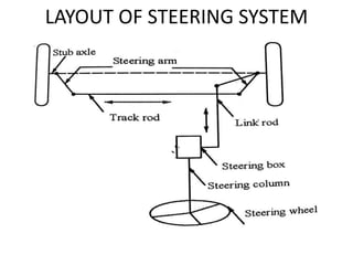
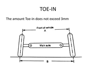
UNIT-IV
STEERING, BRAKES AND
SUSPENSION SYSTEMS
• Function of steering system:
• It provides wheels swinging to the left of right
• It provides vehicle turning as per the will of the
driver
• It provides the directional stability
• It helps to control wear and tear of tyres
• It helps in achieving the self rightening effect
• It converts the rotary movement of the steering
wheel into an angular turn of front wheels
• It multiples the effort of the driver by leverage to
make wheels easy to turn
• It absorbs a major part of road shocks in such a way
from being transmitted to hands of the driver.
LAYOUT OF STEERING SYSTEM
• Steering wheel: control wheel to steer a vehicle
by the driver. It contains traffic indicator switch,
light switch, wiper switch.
• Steering linkage: Steering wheel are turned by
the steering linkage. It consists of pitman arm,
ball joints, drag link, steering arm, spindle, tie
rod kingpin assembly.
• Pitman arm: In which converts the output
torque from the steering gear into force to the
drag link.
• Drag link: It is connected between pitman arm
and steering arm.
• Ball joints: these joints are connected at both
ends of the drag link and tie rod. It performs the
angular displacement, rotational movement of
the drag link and tie rod produced by the front
wheel rotation.
• Tie rod: It is tubular member. Both the left and
right tie rod arms are connected by this tie rod.
The force is transmitted between these two
components.
• Steering gear: The pitman arm is splined to the
steering gear box rocker arm at one end and the
other end is connected to the drag link by a ball
joint.
STEERING GEOMETRY
• Castor
• Camber
• Kingpin inclination
• Toe-in
• Toe-out
• Requirements of the steering system:
• It multiples the turning efforts applied on the
steering wheel by the driver
• The shocks of the road surface absorbed by wheel
should not be transmitted to the driver’s hand.
• When ever driver releases the steering wheel
after completing the turn, the wheel should
achieve a straight ahead position immediately.
• It must keep the wheel at all time in rolling
motion without rubbing on the road.
• It must be light and stable
• It must easily be operated with less maintenance.
• Function of the steering system:
• It provides wheels swinging to the left or right
• It provided vehicle turning as per the will of the
driver
• It provides the directional stability
• It helps to control wear and tear of tyres
• It helps in achieving the self rightening effect
• It converts the rotary movement of the steering
wheel into an angular turn of front wheels.
• It absorbs a major part of road shocks in such a
way from being transmitted to hands of the
driver.
CAMBER
The camber should not exceed to 2 degree
• Effects of wheel camber:
• Bending stresses in the kingpin and stub axle are
reduced.
• Steering effort is drastically reduced.
• Shock loads are not permitted to transmit to the
steering wheel at high speeds
• It imparts the directional stability.
CASTER
Castor angle ranges from 2 to 7 degree in modern vehicles
KINGPIN INCLINATION
• The angle between vertical line and centre of
the kingpin when viewing from the front of
the vehicle. It varies from 3.5 to 7.5 degrees
• Effect: Both kingpin inclination and castor give
directional stability.
• Particulary steering effort is reduced when the
vehicle is stationary.
• Tyre wear also is greatly reduced.
TOE-IN
The amount Toe-in does not exceed 3mm
WHEEL ALIGNMENT
• The positioning of front wheel and steering
mechanisms.
• It provides a good directional stability, easy
steering, minimum tyre wear and good riding
qualities to vehicles.
• Excessive tyre wear, vibration, hard steering,
shimmy etc, are produced because of incorrect
of wheels.
• 1. Castor 2. Camber, 3.Toe-in 4.Toe-out
• 5. Kingpin inclination.
• The following checking, inspection and adjustment
are carried out.
• Wheel bearing adjustment should be checked and
correction should be carried out if it is required to
keep the parameters within specified limit.
• Kingpin and their bushing should be checked and
thoroughly inspected for excessive play
• Spring should be checked for breaks
• Bending of the steering arms should be checked.
• Due to incorrect toe-on turning it results the
wearing of tyres
• Factors such as frame alignment, spring condition,
position of the rear axle condition of the shock
absorbers etc., should be checked.
Steering gears
• Rotary motion of the steering wheel is converted
into straight line motion of the linkage by the
steering gear.
• Two types of steering gears
• 1.The pitman-arm type and
• 2.The rack-and-pinion type
• Steering gear converts the turning motion of the
steering wheel into to and fro motions of the link
rod of the steering linkage.
• Steering gear assembly not only steers from
wheels but it also reduces the steering wheel
turning effort by increasing the output torque.
• The reduction ratio is known as steering ratio.
Steering gear box & types
• Worm and roller
• Worm and sector
• Cam and roller
• Cam and peg
• Cam and turn lever
• Screw and nut
• Recirculating ball
• Rack and pinion
• Worm and ball bearing
Recirculating Ball Type Steering Gear
Box
Rack and Pinion type Steering Gear
Box
• Steering ratio:
• Number of turns on the steering wheel required
to produce one turn of the steering gear cross
shaft. (OR) the ratio of the output force to the
input force applied.
• The number of degrees through which the
steering wheel is turned is divided into number of
degrees for which front wheels turn is known as
overall steering ratio.
• The steering ratio ranges from 11:1 to 24:1 in
passenger car having no power steering.
• This ratio varies from 15 to 20% higher than
steering gear ratio in both manual steering &
power steering.
• Steering gear ratio: The ratio between number of
degrees of rotation on the steering wheel and
number of degrees through which the cross shaft
is free to rotate at the same time.
• High steering ratio is called slow steering because
the steering wheel has to be turned for many
degrees to obtain a small steering effect.
• Low steering ratio is called fast or quick steering
because the steering wheel has to be turned to
obtain a large effect.
• There are two factors:
• 1. Steering linkage ratio, and
• 2. Gear ratio in the steering gear
• Steering linkage ratio is determined by the
relative length of the pitman arm and the steering
arm.
• If the effective lengths of the pitman arm and the
steering arm are equal, the linkage has a ratio of
1:1.
• If the pitman arm is shorter than steering arm ,
the linkage ratio will be less than 1:1.
• Understeering and Oversteering:
• The centrifugal force exerts on wheels during a
turn.
• When the slip angles at front wheels are greater
than rear wheels. The radius of the turn increases,
• At this condition, the vehicle turns less than the
rotation given by the steering wheel. Otherwise the
vehicle will try to move away from its normal
direction of motion.
• The vehicle is kept on the right path
• The vehicle is needed to steer for a little more than
the theoretical steer. This condition of understeer.
• Some disadvantages in manual steering:
• It is bigger and heavier in engines on cars
• Low pressure tyres should be used in case of cars.
• The larger steering ratio is required to steer these
cars. For more turns of the steering wheel are
required to move to the desired distance.
• Power steering system uses compressed air,
electrical devices and hydraulic pressure.
• Hydraulic oil pressure is used in all cars an most
trucks having power steering systems.
• Power steering is to improve the driving comfort.
• Two types:
• Integral type and Linkage type.
• Integral type, the power piston is integrated
along with the steering gear. Power piston is
connected to the frame.
• Steering linkage in case linkage type.
• Power steering is used to wheel turning effort, to
turn sharp corner easily, to negotiate winding
roads and to move vehicles in a confined space
and also to offer some resistance to make the
driver feel and retain.
• POWER STEERING
• This system is used in big cars and heavy
commercial vehicles.
• It is very much suitable for low speed and the
vehicle for parking purpose while reversing.
• Function of front axle:
• It turns the front wheel easily
• It provides a cushioning effect though a spring
• It takes the weight of front vehicle
• It provides steering action
• The spring transmits cushion effect to the vehicle
• It controls the ride through shock absorber
• It takes the braking system
• It transmits power to the front wheels in case of
four wheel drive
• It carries both the hub and wheels
• Stub axle:
• The steering have to turn the front wheel. It is done by
hinging the stub axle with steering knuckle at the axle
beam.
• Types of stub axle:
• Elliot: It is connected to the front stub axle by placing in
the yoke end with a kingpin and cotter is used to join these
tothether
• Reversed elliot: the arrangement is reversed. The kingpin if
fixed in the axle beam.Its ends turn in the forks of the
steering knuckle.
• Lamoine:L shaped spindle is used instead of yoke type
hinge.
• Reversed lamoine: The construction is similar to the
lamoine stub axle but the upside of the axle is inverted so
that the wheel axle is below the axle beam. Modern
vehicles the front axles are straight.
• SUSPENSION SYSTEM:
• Chassis of vehicle is connected to the front and rear
through the medium of springs, shock absorbers and
axles. All parts perform the function of protecting
parts from shocks .
• Suspension system has a spring and damper. The
energy of road shock produced by the spring
oscillates. These oscillations are arrested by the
damper knows as shock absorber.
• Spring: used to shocks from road surface
• Dampers: shock absorbers used to improve a riding
comport
• Stabilizer: sway bar or anti roll bar is to prevent
lateral swinging of the car
• A linkage system to control the longitudinal and
lateral movements of wheels.
• Function of suspension system:
• To eliminate road shocks from transmission to
vehicle components
• To keep the proper steering geometry
• To obtain a particular height to body structure
• To resist the torque and braking reactions
• To minimize the effects of stresses due to road
shocks on the mechanism & provide a
cushioning effect
• To prevent the structure of the vehicle from
shock loading and vibration due to irregularities
of the road surface
• To obtain the requisite height to body structure
• Sprung Weight and Unsprung Weight:
• Sprung: the body of vehicle is supported by spring. The weight
of the body is supported by springs called sprung.
• Wheels, axles and other parts of the automobile which are not
supported by spring called the unsprung.
• Types of suspension springs:
• 1. Steel springs:
a. Leaf springs, b. Tapered leaf springs
b. Coil springs, 4. Torsion bar
2. Rubber springs:
a. Compression springs b. Compression – shear spring
c. Steel reinforced springs, d. Progressive spring
e. Face shear spring
3. Air springs
a. Bellow type springs, b. Piston type spring
4. Plastic spring.
• Leaf Spring Suspension
• Length of the spring: shorter spring will have
higher stiffness
• Width of the spring: wider spring will have higher
stiffness
• Thickness of the leaf: Thicker leaf will have higher
stiffness
• Number of leaves: greater the number of leaves
higher the stiffness
• Types of spring:
• Semi elliptical spring, Quarter elliptical, three
quarter elliptical, full elliptical, transverse spring,
Platform type spring.
Helper springs
Coil Spring
• Coil spring:
• Coil wire if a steel wire
• Required length is coiled throughout
• Coil springs are used both rear & front independent
suspensions
• Energy stored per unit volume is twice in the coil
spring compared to leaf spring
• Coil spring carries both shear and bending stresses
but torque reaction & side thrust cannot be carried
out.
• Both driving reaction and braking torque are also
considered in arranging the coil spring.
• Two types:
• Tension, and Compression spring.
• Torsion bar is a steel bar operated by both twisting and
shear stress
• Two long steel bars form springs
• Torsion bar can be used with independent suspensions
• When the wheel strikes a bump, it will start to vibrate up
and down thereby producing torque on the torsion bar
called spring.
• Torsion bar spring is lighter in Wt compared to leaf spring
• It also occupies less space
• Torsion tubes replace torsion bars in many cases
• Main Disadvantages: Does not carry the braking or driving
torque
• Additional linkages are needed
• Absence of friction force, damping is required to absorb
road shocks.
Telescopic shock absorber
• Advantages:
• Large amount of energy is dissipated due to large
volume of fluid displaced without causing a high
temp rise
• There is no wear development in the damper with
the connecting arm pivots
• The applied force is increased when compared to
indirect acting type
• The leakage is very less due to lower pressure and
absence of the rotating shaft entering the reservoir
• Cost is less than springs
• No need of topping up is necessary in most of the
telescopic dampers
• Air suspension system:
• Air springs are used in air suspension systems
• Metal spring is removed & an air bag referred to an
air spring, is inserted or fabricated to fit in the place
of the factory spring
• Air pressure is supplied to the air bag, the
suspension can be adjusted either up or down
• Air spring is nothing but a flexible bellows made for
textile-reinforced rubber, containing compressed air
which is used to carry load on vehicles.
• Air pressure inflates the bellows and raises the
chassis from the axle
• Used on many heavy duty trucks , trailers and buses
DRUM BRAKE
DISC BRAKES
PNEUMATIC BRAKES
• When the pressure attains the upper limit, this valve get
opened to allow air to the atmosphere
• Brake valve is connected to the driver pedal which controls
the air pressure acting on four brake chambers
• When the driver releases the brake pedal, force is exerted
on spring and piston
• Exhaust valve seat will also move downward when the
piston moves downwards to contact the exhaust valve and
seals the exhaust opening in the piston stem
• Driver releases the pedal fully the graduated spring is
compressed and strike by the piston shoulder in the body.
• The inlet valve is fully opened and full air tank pressure is
admitted to pass through brake valve into the brake
chamber
HYDRAULIC CYLINDER
• Mater cylinder:
• Purpose:
• The required hydraulic pressure is built up to operate
the system
• It maintains a constant volume of fluid in the system
• To bleed or force air out of the brake line and wheel
cylinder, a pump is used.
• Main parts of a mater cylinder:
• Brake fluid reservoir
• Cylinder or compression chamber
• Piston assembly
• Check valve or control valve
• Piston return spring
MASTER CYLINDER
VACCUM SERVO BRAKE
ANTILOCK BRAKING SYSTEM(ABS)
• Components of ABS:
• Wheel speed sensors(pick up and exciter)
• Electronic control unit(ECU)
• Hydraulic modulator valves
• Pump motor and accumulator
• Wheel speed sensors: consists of magnetic pickup and
toothed sensor ring are mounded in steering knuckles,
wheel hub, brake backing plates, differential housing.
Wheel speed sensor pickup has a magnetic core
surrounded by coil windings. When wheel turns, teeth
on the sensor ring move through the pickup magnetic
field. The number of voltage pulses per second is
induced in the pickup change in direct proportion to
the wheel speed.
• ECU: ECU processes all ABS information and signal
functions. It receives and interprets voltage pulses
generated by the sensor pickup as the exciter
teeth pass by and its uses this information.
• Hydraulic modulator valve: Valves regulate the
fluid pressure to brake during ABS action. ECU
commands the modulator valve to either
Change the fluid pressure to the brake chamber
Hold the existing pressure
ABS solenoid valves for each brake circuit. The
exact number of valves per circuit depends on
ABS system.
ANTILOCK BRAKING SYSTEM(ABS)
TRACTION CONTROL

Unit iv-

  • 1.
  • 2.
    • Function ofsteering system: • It provides wheels swinging to the left of right • It provides vehicle turning as per the will of the driver • It provides the directional stability • It helps to control wear and tear of tyres • It helps in achieving the self rightening effect • It converts the rotary movement of the steering wheel into an angular turn of front wheels • It multiples the effort of the driver by leverage to make wheels easy to turn • It absorbs a major part of road shocks in such a way from being transmitted to hands of the driver.
  • 3.
  • 4.
    • Steering wheel:control wheel to steer a vehicle by the driver. It contains traffic indicator switch, light switch, wiper switch. • Steering linkage: Steering wheel are turned by the steering linkage. It consists of pitman arm, ball joints, drag link, steering arm, spindle, tie rod kingpin assembly. • Pitman arm: In which converts the output torque from the steering gear into force to the drag link. • Drag link: It is connected between pitman arm and steering arm.
  • 5.
    • Ball joints:these joints are connected at both ends of the drag link and tie rod. It performs the angular displacement, rotational movement of the drag link and tie rod produced by the front wheel rotation. • Tie rod: It is tubular member. Both the left and right tie rod arms are connected by this tie rod. The force is transmitted between these two components. • Steering gear: The pitman arm is splined to the steering gear box rocker arm at one end and the other end is connected to the drag link by a ball joint.
  • 6.
    STEERING GEOMETRY • Castor •Camber • Kingpin inclination • Toe-in • Toe-out
  • 7.
    • Requirements ofthe steering system: • It multiples the turning efforts applied on the steering wheel by the driver • The shocks of the road surface absorbed by wheel should not be transmitted to the driver’s hand. • When ever driver releases the steering wheel after completing the turn, the wheel should achieve a straight ahead position immediately. • It must keep the wheel at all time in rolling motion without rubbing on the road. • It must be light and stable • It must easily be operated with less maintenance.
  • 8.
    • Function ofthe steering system: • It provides wheels swinging to the left or right • It provided vehicle turning as per the will of the driver • It provides the directional stability • It helps to control wear and tear of tyres • It helps in achieving the self rightening effect • It converts the rotary movement of the steering wheel into an angular turn of front wheels. • It absorbs a major part of road shocks in such a way from being transmitted to hands of the driver.
  • 9.
    CAMBER The camber shouldnot exceed to 2 degree
  • 10.
    • Effects ofwheel camber: • Bending stresses in the kingpin and stub axle are reduced. • Steering effort is drastically reduced. • Shock loads are not permitted to transmit to the steering wheel at high speeds • It imparts the directional stability.
  • 11.
    CASTER Castor angle rangesfrom 2 to 7 degree in modern vehicles
  • 12.
    KINGPIN INCLINATION • Theangle between vertical line and centre of the kingpin when viewing from the front of the vehicle. It varies from 3.5 to 7.5 degrees • Effect: Both kingpin inclination and castor give directional stability. • Particulary steering effort is reduced when the vehicle is stationary. • Tyre wear also is greatly reduced.
  • 13.
    TOE-IN The amount Toe-indoes not exceed 3mm
  • 14.
    WHEEL ALIGNMENT • Thepositioning of front wheel and steering mechanisms. • It provides a good directional stability, easy steering, minimum tyre wear and good riding qualities to vehicles. • Excessive tyre wear, vibration, hard steering, shimmy etc, are produced because of incorrect of wheels. • 1. Castor 2. Camber, 3.Toe-in 4.Toe-out • 5. Kingpin inclination.
  • 15.
    • The followingchecking, inspection and adjustment are carried out. • Wheel bearing adjustment should be checked and correction should be carried out if it is required to keep the parameters within specified limit. • Kingpin and their bushing should be checked and thoroughly inspected for excessive play • Spring should be checked for breaks • Bending of the steering arms should be checked. • Due to incorrect toe-on turning it results the wearing of tyres • Factors such as frame alignment, spring condition, position of the rear axle condition of the shock absorbers etc., should be checked.
  • 16.
    Steering gears • Rotarymotion of the steering wheel is converted into straight line motion of the linkage by the steering gear. • Two types of steering gears • 1.The pitman-arm type and • 2.The rack-and-pinion type • Steering gear converts the turning motion of the steering wheel into to and fro motions of the link rod of the steering linkage. • Steering gear assembly not only steers from wheels but it also reduces the steering wheel turning effort by increasing the output torque. • The reduction ratio is known as steering ratio.
  • 17.
    Steering gear box& types • Worm and roller • Worm and sector • Cam and roller • Cam and peg • Cam and turn lever • Screw and nut • Recirculating ball • Rack and pinion • Worm and ball bearing
  • 18.
    Recirculating Ball TypeSteering Gear Box
  • 19.
    Rack and Piniontype Steering Gear Box
  • 20.
    • Steering ratio: •Number of turns on the steering wheel required to produce one turn of the steering gear cross shaft. (OR) the ratio of the output force to the input force applied. • The number of degrees through which the steering wheel is turned is divided into number of degrees for which front wheels turn is known as overall steering ratio. • The steering ratio ranges from 11:1 to 24:1 in passenger car having no power steering. • This ratio varies from 15 to 20% higher than steering gear ratio in both manual steering & power steering.
  • 21.
    • Steering gearratio: The ratio between number of degrees of rotation on the steering wheel and number of degrees through which the cross shaft is free to rotate at the same time. • High steering ratio is called slow steering because the steering wheel has to be turned for many degrees to obtain a small steering effect. • Low steering ratio is called fast or quick steering because the steering wheel has to be turned to obtain a large effect. • There are two factors: • 1. Steering linkage ratio, and • 2. Gear ratio in the steering gear
  • 22.
    • Steering linkageratio is determined by the relative length of the pitman arm and the steering arm. • If the effective lengths of the pitman arm and the steering arm are equal, the linkage has a ratio of 1:1. • If the pitman arm is shorter than steering arm , the linkage ratio will be less than 1:1.
  • 23.
    • Understeering andOversteering: • The centrifugal force exerts on wheels during a turn. • When the slip angles at front wheels are greater than rear wheels. The radius of the turn increases, • At this condition, the vehicle turns less than the rotation given by the steering wheel. Otherwise the vehicle will try to move away from its normal direction of motion. • The vehicle is kept on the right path • The vehicle is needed to steer for a little more than the theoretical steer. This condition of understeer.
  • 25.
    • Some disadvantagesin manual steering: • It is bigger and heavier in engines on cars • Low pressure tyres should be used in case of cars. • The larger steering ratio is required to steer these cars. For more turns of the steering wheel are required to move to the desired distance. • Power steering system uses compressed air, electrical devices and hydraulic pressure. • Hydraulic oil pressure is used in all cars an most trucks having power steering systems. • Power steering is to improve the driving comfort.
  • 26.
    • Two types: •Integral type and Linkage type. • Integral type, the power piston is integrated along with the steering gear. Power piston is connected to the frame. • Steering linkage in case linkage type. • Power steering is used to wheel turning effort, to turn sharp corner easily, to negotiate winding roads and to move vehicles in a confined space and also to offer some resistance to make the driver feel and retain.
  • 27.
  • 30.
    • This systemis used in big cars and heavy commercial vehicles. • It is very much suitable for low speed and the vehicle for parking purpose while reversing.
  • 32.
    • Function offront axle: • It turns the front wheel easily • It provides a cushioning effect though a spring • It takes the weight of front vehicle • It provides steering action • The spring transmits cushion effect to the vehicle • It controls the ride through shock absorber • It takes the braking system • It transmits power to the front wheels in case of four wheel drive • It carries both the hub and wheels
  • 34.
    • Stub axle: •The steering have to turn the front wheel. It is done by hinging the stub axle with steering knuckle at the axle beam. • Types of stub axle: • Elliot: It is connected to the front stub axle by placing in the yoke end with a kingpin and cotter is used to join these tothether • Reversed elliot: the arrangement is reversed. The kingpin if fixed in the axle beam.Its ends turn in the forks of the steering knuckle. • Lamoine:L shaped spindle is used instead of yoke type hinge. • Reversed lamoine: The construction is similar to the lamoine stub axle but the upside of the axle is inverted so that the wheel axle is below the axle beam. Modern vehicles the front axles are straight.
  • 35.
    • SUSPENSION SYSTEM: •Chassis of vehicle is connected to the front and rear through the medium of springs, shock absorbers and axles. All parts perform the function of protecting parts from shocks . • Suspension system has a spring and damper. The energy of road shock produced by the spring oscillates. These oscillations are arrested by the damper knows as shock absorber. • Spring: used to shocks from road surface • Dampers: shock absorbers used to improve a riding comport • Stabilizer: sway bar or anti roll bar is to prevent lateral swinging of the car • A linkage system to control the longitudinal and lateral movements of wheels.
  • 36.
    • Function ofsuspension system: • To eliminate road shocks from transmission to vehicle components • To keep the proper steering geometry • To obtain a particular height to body structure • To resist the torque and braking reactions • To minimize the effects of stresses due to road shocks on the mechanism & provide a cushioning effect • To prevent the structure of the vehicle from shock loading and vibration due to irregularities of the road surface • To obtain the requisite height to body structure
  • 37.
    • Sprung Weightand Unsprung Weight: • Sprung: the body of vehicle is supported by spring. The weight of the body is supported by springs called sprung. • Wheels, axles and other parts of the automobile which are not supported by spring called the unsprung. • Types of suspension springs: • 1. Steel springs: a. Leaf springs, b. Tapered leaf springs b. Coil springs, 4. Torsion bar 2. Rubber springs: a. Compression springs b. Compression – shear spring c. Steel reinforced springs, d. Progressive spring e. Face shear spring 3. Air springs a. Bellow type springs, b. Piston type spring 4. Plastic spring.
  • 38.
    • Leaf SpringSuspension
  • 39.
    • Length ofthe spring: shorter spring will have higher stiffness • Width of the spring: wider spring will have higher stiffness • Thickness of the leaf: Thicker leaf will have higher stiffness • Number of leaves: greater the number of leaves higher the stiffness • Types of spring: • Semi elliptical spring, Quarter elliptical, three quarter elliptical, full elliptical, transverse spring, Platform type spring.
  • 40.
  • 41.
  • 42.
    • Coil spring: •Coil wire if a steel wire • Required length is coiled throughout • Coil springs are used both rear & front independent suspensions • Energy stored per unit volume is twice in the coil spring compared to leaf spring • Coil spring carries both shear and bending stresses but torque reaction & side thrust cannot be carried out. • Both driving reaction and braking torque are also considered in arranging the coil spring. • Two types: • Tension, and Compression spring.
  • 44.
    • Torsion baris a steel bar operated by both twisting and shear stress • Two long steel bars form springs • Torsion bar can be used with independent suspensions • When the wheel strikes a bump, it will start to vibrate up and down thereby producing torque on the torsion bar called spring. • Torsion bar spring is lighter in Wt compared to leaf spring • It also occupies less space • Torsion tubes replace torsion bars in many cases • Main Disadvantages: Does not carry the braking or driving torque • Additional linkages are needed • Absence of friction force, damping is required to absorb road shocks.
  • 45.
  • 46.
    • Advantages: • Largeamount of energy is dissipated due to large volume of fluid displaced without causing a high temp rise • There is no wear development in the damper with the connecting arm pivots • The applied force is increased when compared to indirect acting type • The leakage is very less due to lower pressure and absence of the rotating shaft entering the reservoir • Cost is less than springs • No need of topping up is necessary in most of the telescopic dampers
  • 47.
    • Air suspensionsystem: • Air springs are used in air suspension systems • Metal spring is removed & an air bag referred to an air spring, is inserted or fabricated to fit in the place of the factory spring • Air pressure is supplied to the air bag, the suspension can be adjusted either up or down • Air spring is nothing but a flexible bellows made for textile-reinforced rubber, containing compressed air which is used to carry load on vehicles. • Air pressure inflates the bellows and raises the chassis from the axle • Used on many heavy duty trucks , trailers and buses
  • 51.
  • 52.
  • 53.
  • 54.
    • When thepressure attains the upper limit, this valve get opened to allow air to the atmosphere • Brake valve is connected to the driver pedal which controls the air pressure acting on four brake chambers • When the driver releases the brake pedal, force is exerted on spring and piston • Exhaust valve seat will also move downward when the piston moves downwards to contact the exhaust valve and seals the exhaust opening in the piston stem • Driver releases the pedal fully the graduated spring is compressed and strike by the piston shoulder in the body. • The inlet valve is fully opened and full air tank pressure is admitted to pass through brake valve into the brake chamber
  • 55.
  • 56.
    • Mater cylinder: •Purpose: • The required hydraulic pressure is built up to operate the system • It maintains a constant volume of fluid in the system • To bleed or force air out of the brake line and wheel cylinder, a pump is used. • Main parts of a mater cylinder: • Brake fluid reservoir • Cylinder or compression chamber • Piston assembly • Check valve or control valve • Piston return spring
  • 57.
  • 58.
  • 59.
  • 60.
    • Components ofABS: • Wheel speed sensors(pick up and exciter) • Electronic control unit(ECU) • Hydraulic modulator valves • Pump motor and accumulator • Wheel speed sensors: consists of magnetic pickup and toothed sensor ring are mounded in steering knuckles, wheel hub, brake backing plates, differential housing. Wheel speed sensor pickup has a magnetic core surrounded by coil windings. When wheel turns, teeth on the sensor ring move through the pickup magnetic field. The number of voltage pulses per second is induced in the pickup change in direct proportion to the wheel speed.
  • 61.
    • ECU: ECUprocesses all ABS information and signal functions. It receives and interprets voltage pulses generated by the sensor pickup as the exciter teeth pass by and its uses this information. • Hydraulic modulator valve: Valves regulate the fluid pressure to brake during ABS action. ECU commands the modulator valve to either Change the fluid pressure to the brake chamber Hold the existing pressure ABS solenoid valves for each brake circuit. The exact number of valves per circuit depends on ABS system.
  • 62.
  • 63.