Download as PDF, PPTX
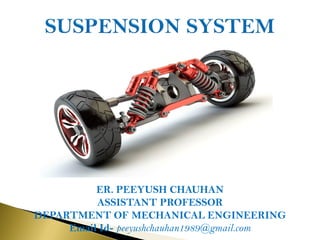
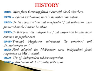


The document discusses the automobile suspension system, which isolates the vehicle from shocks and vibrations using components such as springs and dampers. It outlines the historical development of various suspension types, including independent front and rear suspensions, and describes the functions and mechanisms of springs and shock absorbers. Additionally, it details specialized systems like air suspension and modern technologies used to maintain vehicle stability and comfort.