The document discusses various aspects of steering systems, including:
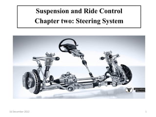
1. The primary and secondary functions of steering systems which allow the driver to control vehicle direction and provide stability and feedback.
2. Common causes of stiff steering like insufficient lubrication or incorrect tire pressure and alignment.
3. Requirements of a good steering system including accuracy, ease of handling, and minimal effort.
4. Types of front axles including live and dead axles and their characteristics.