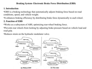
20ME603PE-
Automobile Engineering
UNIT Iv - STEERING, BRAKES AND SUSPENSION
SYSTEMS
Prepared By
Chandra kumar S
Assistant professor
Kongunadu college of
engineering and technology
STEERING SYSTEM
Introduction
•The steering system provides directional control and stability to the
automobile.
•It ensures smooth movement with minimal strain on the driver.
•Steering changes the wheel direction to turn left or right.
•Safety depends on proper maintenance of the steering and braking
systems.
Importance of Steering System
•Prevents accidents caused by steering failures.
•Ensures controlled vehicle movement and stability.
•Allows smooth turning without excessive tire wear.
•Helps the driver maintain proper control over speed and direction.
STEERING SYSTEM
Steering System Requirements
•Multiplies the turning effort applied by the driver.
•Absorbs road shocks to prevent transmission to the driver’s hands.
•Ensures self-rightening effect after turning.
•Keeps wheels rolling without rubbing on the road.
•Aids in controlling vehicle speed.
•Must be light, stable, and require minimal maintenance.
Functions of the Steering System
•Allows wheels to swing left or right.
•Provides vehicle turning control as per driver’s will.
•Maintains directional stability.
•Reduces tire wear and tear.
•Absorbs road shocks to protect the driver.
Components Ensuring Steering Functionality
•Steering gears – Located at the end of the steering column.
•Linkage system – Connects the steering gear to the wheels.
STEERING SYSTEM
Components Ensuring Steering Functionality
•Steering gears – Located at the end of the steering column.
•Linkage system – Connects the steering gear to the wheels.
Layout of Conventional Steering System:
Components of Conventional Steering System
The following are the main components of steering system.
•Steering wheel.
•Steering column or shaft.
•Steering gear.
•Drop arm or pitman arm.
•Ball joints.
•Drag link.
•Steering arm.
•Stub axle.
•Left spindle and kingpin.
•Left tie rod arm.
•Track rod or tie-rod.
•Right tie rod arm, spindle and kingpin.
•Steering stops.
Principle of Operation of the Steering System
• The steering system operates using a worm drive mechanism in the steering
gearbox.
• The driving worm is fixed to the end of the steering tube and rotates when the
steering wheel is turned.
• A cross shaft connected to the driven gear rotates at a right angle to the steering
tube, changing the motion direction.
• The output shaft moves the pitman arm, transmitting motion to the steering
knuckles via the drag link and intermediate steering arm.
Right Turn Process
• Steering wheel and tube rotate clockwise.
• The bottom end moves forward, pushing the drag link.
• The intermediate steering arm forces the tie rods to the left.
• The right tie rod pulls the right steering knuckle, turning the right wheel right.
• The left tie rod pushes the left steering knuckle, turning the left wheel right.
Left Turn Process
• The same steps occur but in reverse directions.
Fundamentals of Steering Mechanism (or) Condition for True Rolling Motion
Introduction
•The steering system converts rotary movement of the steering
wheel into an angular turn of the wheels.
•Ensures straight-ahead motion at high speed and changes vehicle
direction with minimal effort.
•The wheels must exhibit pure rolling motion without skidding.
Concept of True Rolling Motion
•During a turn, wheels should follow a definite radius originating
from a common center (instantaneous center).
•The inner wheel turns more than the outer wheel to prevent lateral
slipping.
•This relationship is governed by the steering geometry of the
vehicle.
Fundamentals of Steering Mechanism (or) Condition for True Rolling Motion
Mathematical Condition for True Rolling Motion
•Ensures smooth and stable maneuvering on curves.
Key Steering Principle
•Steering is achieved by turning the axes of rotation of the front wheels relative to the chassis.
•The inner wheel must rotate through a larger angle than the outer wheel to satisfy true
rolling motion.
•The steering mechanism should always satisfy the given equation for any turning radius.
Conclusion
•The correct steering geometry ensures safety, stability, and reduced tire wear.
•A well-designed steering mechanism improves handling and prevents skidding during turns.
Ackerman - Jeantaud Steering Linkage
Introduction
•The Ackerman-Jeantaud steering linkage is a four-bar mechanism used for
proper steering geometry.
•It consists of:
– Two long links (AC & KL) of unequal lengths.
– Two short links (AK & CL) of equal lengths.
Ackerman - Jeantaud Steering Linkage
Working Principle
•When the vehicle moves straight, longer links (AC & KL) remain parallel, and
shorter links (AK & CL) are inclined at an angle α.
•For turning:
– The short link rotates, increasing α for a right turn.
– The left front axle turns less than the right front axle, ensuring correct
steering geometry.
•The value of steering angles ( & )
ɸ ɵ depends on the ratio AK/AC and angle α.
Conclusion
•Ensures proper turning without tire skidding.
•Errors are minimal for small steering angles but can increase at larger angles.
•Helps achieve smooth and stable maneuvering by allowing different turning
angles for inner and outer wheels.
Ackerman - Jeantaud Steering Linkage
Davis Steering Gear
•Davis steering gear is an exact steering mechanism ensuring true rolling
motion.
•It consists of slotted links (AK & BL) connected to the left and right
front wheels.
•The link KL moves parallel to AB to achieve steering.
Davis Steering Gear
Working Principle
•Slotted links AK & BL pivot at A & B and connect to link KL via sliding-turning pairs.
•The link KL moves left or right, causing the wheels to steer accordingly.
•When the mechanism is in its mid-position, wheels are aligned for straight motion.
•Steering occurs by shifting KL, changing wheel angles θ & ɸ to maintain correct geometry.
Advantages of Davis Steering Gear
•Ensures accurate and pure rolling motion for all steering angles.
•Provides correct steering for all positions, unlike Ackerman steering gear.
•Reduces tire wear due to improved wheel alignment.
Limitations
•More complex and expensive due to sliding pairs.
•Increased friction and wear compared to Ackerman mechanism.
Conclusion
•Davis steering gear provides more accurate steering than Ackerman but has higher
maintenance due to sliding friction.
•Suitable for precise steering applications where accuracy is more critical than mechanical
efficiency.
Steering Linkage for Vehicle with Independent Front Suspension
•Rigid Axle Suspension: The main axle beam restricts stub axle movement to the horizontal
plane, ensuring no vertical deflection and no change in track rod length.
•Independent Suspension: Stub axles move independently up or down, causing continuous
variation in the distance between ball-joint ends of the track rod arms.
•Issue with Single Track Rod: A conventional single-track rod system cannot accommodate
the independent movement of stub axles.
•Three-Piece Track Rod System:
•Relay Rod: The central portion of the track rod, connected to an idler arm (on the body
structure) and the drop arm of the steering gear via ball joints.
•Horizontal Movement: The relay rod moves only in the horizontal plane.
•Vertical Movement Accommodation: The outer portions of the system allow for vertical
movements.
•Ensures Effective Steering: The three-piece track rod setup maintains proper steering
function despite independent wheel movement.
Steering Geometry
Steering Geometry Overview:
•Steering geometry defines the angular relationship between steering linkages and front wheels.
•It includes key angles that impact handling, stability, and tire wear.
Important Steering Angles:
– Camber
– Castor
– Kingpin inclination
– Toe-in
– Toe-out
Camber:
Angle between the vertical line and the center line of the tire when viewed from the
front.
Positive camber: Wheels tilt outward at the top.
Negative camber: Wheels tilt inward at the top.
•Excessive positive camber causes outer tire wear.
•Zero camber is ideal for maximum tire life and straight-line stability.
•Slight camber difference is provided for different driving conditions (e.g., right-side camber
higher in India).
Steering Geometry
Castor:
•Angle between vertical line and kingpin axis when viewed from the side.
•Positive castor: Kingpin top tilts backward.
•Negative castor: Kingpin top tilts forward.
•Ranges from 2° to 7° in modern vehicles.
•Provides directional stability and helps wheels return to a straight position.
•Excessive positive castor causes vehicle roll-out, while excessive negative castor leads to
toe-out.
Steering Geometry
Kingpin Inclination:
•Angle between the kingpin axis and the vertical when viewed from the front.
•Effects:
– Improves directional stability along with castor.
– Reduces steering effort, especially when stationary.
– Minimizes tire wear.
– Helps wheels return to a straight position after turning.
Toe-in and Toe-out:
•Toe-in: Front ends of the wheels are closer than rear ends (helps stability and reduces tire
wear).
•Toe-out: Front ends of the wheels are farther apart than rear ends (helps with turning
stability).
•Improper toe settings lead to tire wear, instability, and scrubbing.
Toe In Toe Out
Steering Geometry
Combined Angle and Scrub Radius:
•Combined angle: Sum of camber and kingpin inclination.
•Scrub radius: Distance between the tire centerline and the steering axis intersection with
the ground.
– Positive scrub radius: Causes toe-out.
– Negative scrub radius: Causes toe-in.
– Zero scrub radius: Ideal for stability (center point steering).
•Larger scrub radius increases steering effort and uneven braking.
Steering Geometry
Effect of combined angle variation in rear-wheel-
drive vehicle
Wheel Alignment
Definition: Positioning of front wheels and steering components to ensure stability, smooth
steering, minimal tire wear, and better ride quality.
Importance: Prevents excessive tire wear, vibration, hard steering, and shimmy caused by
misalignment.
Key Factors in Wheel Alignment:
•Castor – Affects directional stability.
•Camber – Impacts tire wear and handling.
•Toe-in – Ensures parallel rolling of wheels.
•Toe-out – Prevents tire scrubbing during turns.
•Kingpin Inclination – Reduces steering effort and improves stability.
Wheel Alignment Procedure:
•Ensure camber, castor, toe-in, and kingpin inclination are set within manufacturer specifications.
•Full vehicle weight should be on the ground during adjustment.
•Check and adjust:
– Wheel bearings for proper fit.
– Kingpins and bushings for excessive play.
– Springs for sagging or damage.
– Steering arms for bending.
– Frame alignment, rear axle position, and shock absorber condition.
Wheel Alignment
Factors Affecting Front Wheel Alignment:
•Maintaining a straight path.
•Smooth entry and exit from turns.
•Absorbing road shocks effectively.
Steering ratio
•Definition: The ratio of the number of degrees the steering wheel turns to the number of
degrees the front wheels turn.
•Formula:
Typical Range:
•Passenger cars (manual steering): 11:1 to 24:1
•Power steering: 15–20% higher than manual steering
•Rack-and-pinion system: 14:1 to 24:1
Steering ratio
Types of Steering Ratios:
•High Steering Ratio (Slow Steering): Requires more turns of the steering wheel for a
small steering effect (better control but slower response).
•Low Steering Ratio (Quick Steering): Requires fewer turns of the steering wheel for a
large steering effect (faster response but harder to control at high speeds).
Factors Affecting Steering Ratio:
•Steering-Linkage Ratio:
– Depends on the length of the pitman arm and steering arm.
– If the pitman arm is shorter than the steering arm, the linkage ratio is less than 1:1.
– Example: If the pitman arm is twice the length of the steering arm, the steering
linkage ratio is 1:2.
•Steering Gear Ratio:
– Defined by the gear mechanism (e.g., worm-and-sector, rack-and-pinion).
– Variable reduction ratio can be achieved by varying the worm or cam pitch,
making it higher in the straight-ahead position and lower in outer ranges.
•Power steering systems have a steering gear ratio 20% lower than manual steering for
easier handling.
Turning Radius and Slip Angle
Definition: The radius of the circle traced by the outer front wheel when turned to its maximum
angle.
Typical Values:
– Passenger cars: 5 m to 8 m
– Buses/Trucks: Up to 45 feet
Factors Affecting Turning Radius:
– Wheelbase: Longer wheelbase = Larger turning radius.
– Steering knuckle rotation: Maximum rotation exceeds 35° from the straight-ahead
position.
Slip Angle:
•Definition: The angle between the direction the wheel is pointing and the actual path it follows
due to tire tread distortion.
•Cause: Side thrust during turns.
Typical Range:
– Dry pavement: 8°
– Slippery pavement: 10°
Effect:
– Helps in maintaining grip and stability during turns.
– A higher slip angle can reduce vehicle control on slippery surfaces.
Understeering and Oversteering
Understeer:
•Definition: When the slip angles at the front wheels are greater than those at the rear wheels, causing the
vehicle to turn less than the steering input.
•Effect:
– The vehicle moves outward from the intended path.
– The driver needs to steer more than theoretically required.
•Characteristics:
– More stable and predictable.
– Common in front-wheel-drive vehicles.
– Preferred in vehicle design for safety.
Oversteer:
•Definition: When the slip angles at the rear wheels are greater than those at the front wheels, causing the
vehicle to turn more than the steering input.
•Effect:
– The vehicle moves inward from the intended path.
– The driver needs to steer less than theoretically required.
•Characteristics:
– Less stable and harder to control.
– Common in rear-wheel-drive vehicles.
– Requires quick corrective action to prevent skidding.
Centre Point Steering
Definition:
•Centre point steering is a condition where the centre line of the wheel meets the centre
line of the kingpin at the road surface. This arrangement helps reduce bending stress,
splaying effect, and heavy steering resistance.
•Advantages:
•Reduces splaying effect – The forces acting on the wheels are better balanced, preventing
outward push.
•Minimizes bending stress – The wheel rotates around its own axis rather than through an
arc.
•Lighter steering effort – Steering becomes easier as the wheel follows a more natural
turning motion.
•Less wear on the kingpin and stub axle – Reduces stress and extends component life.
Centre Point Steering
Methods to Achieve Centre Point Steering:
•Camber: The stub axle is angled to make the wheel centre line meet the kingpin centre
line.
•Kingpin Inclination: The kingpin is inclined inward at the top to align with the wheel
centre line.
•Dished Wheels: Wheels are shaped to bring the centre closer to the kingpin axis.
Disadvantages:
•Tyre 'spread' effect: Causes the wheel to scrub against the road, leading to heavier
steering.
•Increased tyre wear: More friction results in faster tyre degradation.
Steering Gears
Definition:
•The steering gear converts the rotary motion of the steering wheel into the linear motion of the
steering linkage, enabling the driver to control the vehicle's direction with minimal effort.
Types of Steering Gears:
•Pitman-Arm Type:
– Uses a sector gear and a pitman arm to transfer motion.
– Common in trucks and heavy-duty vehicles.
•Rack-and-Pinion Type:
– Uses a gear and a toothed rack for direct movement.
– Common in modern cars due to better precision and response.
Functions of Steering Gear:
•Reduces driver effort by increasing output torque.
•Steers the front wheels smoothly.
•Provides leverage for better control.
Steering Gear Ratio:
•Defined as the ratio of steering wheel rotation to front wheel turning angle.
•Ranges from 18:1 to 20:1.
•Higher ratio = less steering effort but more turns of the steering wheel.
•Lower ratio = quicker response but heavier steering effort.
Types of Steering Gear Box
1. Cam and roller.
2. Recirculating ball.
3. Rack and pinion.
4. Cam and turn lever.
5. Screw and nut.
6. Cam and peg.
7. Worm and roller.
8. Worm and sector.
9. Worm and ball bearing.
Types of Steering Gear Box
Cam and Follower:
•The Cam and Roller steering gear is a type of steering system where a cam rotates to
move a roller, converting rotary motion into linear motion for steering control.
Construction:
•Cam: Connected to the steering shaft, has spiral grooves.
•Roller: Mounted on a pin and supported by ball bearings, follows the cam’s movement.
•Rocker Lever: Supports the roller and is part of the pitman arm shaft.
•Drop Arm Spindle: Carries a V-shaped roller and moves with the cam rotation.
Working Principle:
•Turning the steering wheel rotates the cam.
•The roller follows the cam’s spiral groove, causing the rocker shaft to rotate.
•This rotation moves the drop arm, controlling the steering linkage.
Advantages:
•Efficient motion transfer with minimal backlash.
•Even load distribution, reducing wear on components.
•Smooth and precise steering response.
Types of Steering Gear Box
Recirculating Ball Type Steering Gear:
The Recirculating Ball Type steering gear is a system that reduces friction between the
steering worm and nut using steel balls, ensuring smoother and more efficient steering.
Construction:
•Worm and Nut: Located at the end of the steering shaft.
•Steel Balls: Placed between grooves of the worm and nut for recirculation.
•Transfer Tube: Guides the recirculating balls back into the system.
•Wheel Sector: Meshed with the nut’s teeth to transfer motion.
•Drop Arm: Connected to the sector, controlling the steering linkage.
Working Principle:
•Turning the steering wheel rotates the worm.
•Steel balls roll in the grooves, moving the nut along the worm’s length.
•The nut’s motion transfers to the wheel sector, moving the drop arm.
•The balls continuously recirculate, reducing friction and wear.
Advantages:
•High efficiency (~90%) due to reduced friction.
•Smooth and precise steering response.
•Durable and reliable, especially for heavy loads
Types of Steering Gear Box
Rack and Pinion Type steering gear :
•The Rack and Pinion Type steering gear is a simple and efficient steering system that converts
the rotational motion of the steering wheel into linear motion of the rack to steer the vehicle.
Construction:
•Rack and Pinion: Converts rotational motion into lateral movement.
•Tie Rods: Connect the rack to the wheels.
•Ball Joints: Allow for the rise and fall of the wheels.
•Universal Joint: Provides flexibility and allows the steering box to be centrally mounted.
•Rubber Boot: Protects the components from dust and dirt.
•Spring Pads: Reduce backlash between the gears.
Working Principle:
•When the driver turns the steering wheel, the pinion rotates.
•The pinion engages with the rack, moving it sideways.
•This lateral movement of the rack moves the tie rods, turning the wheels.
Advantages:
•Simple and lightweight design.
•Provides direct and responsive steering.
•Less friction and high efficiency.
Types of Steering Gear Box
Worm and Roller Type Steering Gear
•The Worm and Roller Steering Gear is a type of steering system where a two-toothed roller
engages with a worm gear to convert rotational motion into the movement of the steering
linkage.
Construction:
•Worm Gear: Located at the end of the steering tube.
•Roller Shaft (Sector Shaft/Pitman Shaft): Engages with the worm gear.
•Roller: Mounted on ball bearings to reduce friction.
•Adjusting Screw: Controls backlash and end float of the rocker shaft.
•Bearings: Resist both radial and end thrust.
Working Principle:
•When the driver turns the steering wheel, the worm shaft rotates.
•The roller moves along the worm’s threads, causing the roller shaft to rotate.
•This movement is transferred to the steering linkage, turning the wheels.
Advantages:
•Reduces friction and wear due to roller bearings.
•Provides a smooth and efficient steering action.
•Minimizes backlash and end float.
Types of Steering Gear Box
Screw and Nut Type Steering Gear
The Screw and Nut Steering Gear is a type of steering mechanism where a nut moves axially
along a threaded screw to convert rotary motion into linear motion, which then controls the
movement of the steering linkage.
Construction:
•Screw: Connected to the steering wheel and has a multi-start Acme thread.
•Nut: Made of phosphor-bronze or steel, moves along the screw.
•Ball-mounted Rocker Arm: Prevents nut rotation and transfers motion.
•Drop Arm Spindle: Moves in a circular path and transfers motion to the steering linkage.
•Bronze Pads: Reduce wear and ensure smooth movement.
•Ball Bearings: Support axial thrust and minimize friction.
Working Principle:
•When the driver turns the steering wheel, the screw rotates.
•The nut moves up and down along the screw.
•This movement is transferred to the drop arm spindle, which rotates in a circular path.
•The drop arm then moves the steering linkage to turn the wheels.
Advantages:
•Smooth operation due to reduced friction.
•Less wear and tear due to bronze pads.
Types of Steering Gear Box
Cam and Peg Type Steering Gear:
•The Cam and Peg Steering Gear is a type of steering mechanism where a tapered peg
engages with a grooved cam on the steering column to convert rotary motion into linear
motion.
Construction:
•Cam: Mounted on the inner steering column.
•Tapered Peg: Engages with the cam and moves along the groove.
•Rocker Arm: Connected to the peg, transferring motion.
•Shims: Control the end float of the column.
•Adjusting Screw: Regulates backlash and end float of the rocker shaft.
Working Principle:
•When the driver turns the steering wheel, the cam rotates.
•The tapered peg follows the cam groove, causing the rocker shaft to rotate.
•This motion is transferred to the steering linkage, turning the wheels.
Advantages:
•Compact and simple design.
•High efficiency in transferring motion.
•Less backlash due to adjustable settings.
Types of Steering Gear Box
Worm and Ball Bearing Steering Gear:
•The Worm and Ball Bearing Steering Gear is a type of steering system that uses steel balls
between a worm gear and a ball nut to ensure smooth motion transfer with minimal friction.
Construction:
•Worm Gear: Connected at the lower end of the steering shaft.
•Ball Nut: Engages with the worm through spiral grooves.
•Steel Balls: Circulate between the worm and nut, reducing friction.
•Return Guides: Ensure continuous recirculation of steel balls.
•Pitman Shaft Sector: Engages with the ball nut teeth for steering motion.
Working Principle:
•Turning the steering wheel rotates the worm gear.
•The ball nut moves along the worm's spiral grooves.
•Steel balls roll between the worm and nut, providing a
frictionless drive.
•As the nut moves, it engages with the pitman
shaft sector, steering the vehicle.
Advantages:
•Smooth and frictionless operation.
•Reduces wear and tear due to rolling motion.
Types of Steering Gear Box
• Worm and Sector Steering Gear
• The Worm and Sector Steering Gear is a type of steering system that transmits
motion from the steering tube to the Pitman arm using a worm and sector
mechanism.
Construction:
• Worm Gear: Case-hardened steel, attached to the inner column.
• Sector Gear: Mounted on bearings made of malleable iron or light alloy casting.
• Rocker Shaft: Forms a part of the worm gear mechanism.
• Lubrication System: Uses gear oil to reduce wear and tear.
Working Principle:
• When the steering wheel is turned, the worm gear rotates.
• The worm meshes with the sector gear, causing it to rotate.
• The sector gear, connected to the Pitman arm, transmits motion to the wheels through
the linkage.
Advantages:
• Simple and durable design.
• Reliable performance in heavy-duty applications.
• Easy maintenance and lubrication.
Power Steering
• Definition:
Power steering is a system that reduces the effort required to steer a vehicle, especially at
low speeds, by using hydraulic pressure, compressed air, or electrical devices to
assist the driver.
Types of Power Steering:
• Integral Type – The power piston is integrated with the steering gear.
• Linkage Type – The power piston is connected between the vehicle frame and steering
linkage (commonly used in trucks).
Working Principle:
• The system assists the driver’s steering input by providing additional force using
hydraulic pressure or electric motors.
• The steering remains functional even when power assist is unavailable, allowing for
manual control in case of system failure.
Working of Power Steering:
Components:
• Fluid reservoir – Stores hydraulic fluid.
• Hydraulic pump – Supplies pressurized oil.
• Control valve – Regulates oil flow to the hydraulic ram.
• Hydraulic ram (cylinder & piston) – Assists in turning the wheels.
• Steering shaft, box, and wheel – Used by the driver to steer the vehicle.
Power Steering
Working Principle:
•Neutral (Straight-Ahead) Position:
– Oil from the pump flows to the control valve.
– If the control valve is neutral, fluid is returned to the reservoir.
– Equal pressure on both sides of the piston keeps it stationary.
•Turning Position:
– Turning the steering wheel moves the control valve.
– One fluid passage closes while another opens, creating a pressure difference.
– High-pressure oil moves the piston, which actuates the steering linkage.
– The fluid on the low-pressure side is returned to the reservoir.
Advantages:
•Reduces steering effort, especially at low speeds.
•Enhances maneuverability for parking and reversing.
•Increases driving comfort, especially in heavy vehicles.
Applications:
•Used in large cars and heavy commercial vehicles to improve steering response and reduce
driver fatigue.
Power Steering
Straight ahead position Turning position
Front Axle
Functions of Front Axle:
•Turns the front wheels easily.
•Provides cushioning through springs.
•Supports the weight of the front vehicle.
•Enables steering action.
•Controls ride through shock absorbers.
•Houses braking components.
•Transmits power to front wheels in four-wheel-drive vehicles.
•Supports the hub and wheels.
Construction & Components:
•Axle Beam – Made of forged steel with an I-section for strength and rigidity.
•Kingpin (Swivel Pin) – Connects stub axle to axle beam, allowing wheel movement.
•Track Rod – Connects stub axle arms via ball joints for steering adjustments.
•Drag Link (Pull & Push Rod) – Connects steering arm to drop arm for steering
movement.
Types of Front Axles:
•Based on Rotation:
– Live Axle – Transmits power to front wheels (used in 4WD and heavy vehicles).
– Dead Axle – Supports vehicle weight but does not rotate (used in most cars).
Front Axle
• Based on Axle Beam Design:
– Straight Axle – Simple, strong, and commonly used.
– Double Drop Axle – Offers better ground clearance.
– Fully Drop Axle – Lowers chassis height for stability.
Applications:
• Dead axles are used in light vehicles.
• Live axles are used in heavy and four-wheel-drive vehicles.
Suspension System
Definition:
•The suspension system connects the vehicle chassis to the front and rear wheels using
springs, shock absorbers, and axles. It absorbs road shocks to provide a smooth ride and
protect vehicle components from stress.
Components of Suspension System:
•Springs – Neutralize shocks from road surfaces.
•Shock Absorbers (Dampers) – Control spring oscillations for riding comfort.
•Stabilizer (Anti-Roll Bar) – Prevents lateral swinging of the car.
•Linkage System – Holds components together and controls wheel movement.
Functions of Suspension System:
•Absorbs road shocks to enhance ride comfort.
•Ensures good road grip during driving, braking, and cornering.
•Maintains proper steering geometry.
•Resists torque and braking reactions.
•Enhances vehicle stability by minimizing rolling, pitching, and vertical movements.
•Reduces mechanical stress on the vehicle frame and body.
•Prevents excessive vibrations and shock loading.
•Keeps the vehicle body level on uneven surfaces.
Suspension System
Requirements of Suspension System:
•Minimum deflection for stability.
•Lightweight design to reduce overall vehicle weight.
•Low maintenance and operating costs for durability.
•Minimized tire wear for extended life.
•Cost-effectiveness for affordability.
Principles of Suspension System:
•Supports the vehicle’s weight.
•Absorbs both large and small road impacts effectively.
•Reduces rolling and pitching movements through proper spring design.
•The suspension system ensures a smoother ride, better handling, and increased safety in
vehicles.
Suspension System
Sprung Weight and Unsprung Weight
•Sprung Weight: The part of the vehicle supported by the suspension springs, including
the body, frame, engine, and passengers.
•Unsprung Weight: The weight of components not supported by springs, such as wheels,
axles, and a portion of the suspension system.
Formula:
Sprung weight=Total weight of vehicle-Unsprung weight.
Effects on Vehicle Performance:
•Higher Sprung Weight: Provides better riding comfort by absorbing road shocks
effectively.
•Higher Unsprung Weight: Leads to increased energy storage from road bumps, causing
disturbances and higher tire deflections. However, it reduces vertical velocity over bumps.
•Lower Unsprung Weight: Results in higher natural frequencies of unsprung components,
improving road handling and reducing tire wear.
•Maintaining an optimal balance between sprung and unsprung weight is essential for a
smooth ride, better handling, and vehicle stability.
Suspension System- Suspension Movements:
Pitching
Bouncing
Rolling
Suspension Movements
Yawing
Types of Suspension Springs
• Steel springs
– Leaf springs
– Tapered leaf springs
– Coil springs
– Torsion bar
• Rubber springs
– Compression springs
– Compression-shear springs
– Steel reinforced springs
– Progressive spring
– Face shear spring
• Air springs
– Bellow type springs
– Piston type springs
• Plastic springs.
Types of Suspension Springs
Leaf Springs:
Definition:
•A leaf spring suspension consists of multiple layers of steel plates (leaves) of varying
lengths, arranged in a semi-elliptical shape. It provides shock absorption and load distribution
in vehicles.
Construction:
•A series of steel leaves are clamped together.
•The spring eye is mounted to the frame using a shackle pin.
•The center portion is fixed to the axle with a V-bolt.
•One end of the spring is rigidly fixed, while the other is mounted with a shackle for
flexibility.
Factors Affecting Stiffness:
•Length of the Spring – Shorter springs have higher stiffness.
•Width of the Leaf – Wider leaves provide more stiffness.
•Thickness of the Leaf – Thicker leaves increase stiffness.
•Number of Leaves – More leaves result in greater stiffness.
•Friction Reduction Methods in Modern Leaf Springs:
•Synthetic rubber buttons at leaf ends.
•Inter-leaf plates made of low-friction materials.
•Reduced number of leaves to minimize noise and wear.
Types of Suspension Springs
Types of Leaf Springs:
•Semi-elliptical Spring – Most commonly used in trucks and rear axles of cars.
•Quarter-elliptical Spring – Found in older small cars, bolted to the frame.
•Three-quarter Elliptical Spring – A combination of semi-elliptical and quarter-elliptical
springs.
•Full-elliptical Spring – Two semi-elliptical springs joined together, used in older
vehicles.
•Transverse Spring – Inverted semi-elliptical spring, mounted across the chassis.
Leaf springs are widely used in trucks, buses, and older vehicles due to their durability
and load-bearing capacity.
Types of Suspension Springs
Helper Springs:
Helper springs are additional springs mounted above the main leaf springs in vehicles,
particularly in trucks and commercial vehicles. They provide extra support when the load
exceeds a certain limit.
Working Principle:
•Under light loads, only the main spring is active.
•When the load increases, the helper spring comes into action, assisting the main spring
in bearing the extra weight.
Characteristics of Helper Springs:
•Provides Rigidity – Helps maintain axle alignment.
•Controls Oscillations – Leaf friction minimizes excessive movement.
•Durability – Suitable for heavy-duty applications.
•Better Load Handling – Suitable for large commercial vehicles carrying fluctuating
loads.
•Absorbs Large Shocks – Less effective for small vibrations but ideal for heavy loads.
•Helper springs improve the stability and load-bearing capacity of vehicles, making them
ideal for trucks, buses, and cargo vehicles.
Types of Suspension Springs
Coil Springs:
Definition:
•A coil spring is a helical steel wire wound into a coil shape. It is commonly used in both
front and rear independent suspension systems for better shock absorption.
•Types of Coil Springs:
•Tension Springs – Extend when force is applied.
•Compression Springs – Compress under load to absorb shocks.
Characteristics of Coil Springs:
•Higher Energy Absorption – Stores more energy per unit volume than leaf springs.
•Soft Springing – Provides a smoother ride.
•No Inter-leaf Friction – Requires shock absorbers for oscillation control.
•Requires Additional Support – Needs suspension arms, lateral control rods, or
linkages to handle lateral forces.
•Coil springs are lightweight, durable, and effective for shock absorption, making them
ideal for modern vehicles and independent suspension systems.
Types of Suspension Springs
Taperlite Springs:
•Taperlite springs, also known as taper leaf springs, have a varying cross-section, with
the leaf being thicker at the center and tapering towards the ends. This design differs
from conventional constant cross-section leaf springs.
Advantages of Taperlite Springs:
•Lightweight – Nearly 60% lighter than conventional leaf springs.
•Reduced Inter-leaf Friction – In single-leaf designs, there is no inter-leaf friction. Even
in multi-leaf designs, friction is significantly lower.
•No Squeaking – Eliminates noise caused by friction between leaves.
•Longer Life – More uniform stress distribution reduces wear and tear.
•Compact Design – Occupies less space compared to conventional springs.
•Prevention of Fretting Fatigue – No moisture accumulation between leaves in single-
leaf designs, reducing the risk of corrosion and fatigue failure.
•Taperlite springs provide better durability, efficiency, and performance, making them
popular in modern vehicle suspension systems.
Types of Suspension Springs
Definition:
The Eligo spring is a helical combination of a coil spring and
rubber. The coil spring provides support and prevents buckling,
while the rubber absorbs displacement and acts as a damper
through internal friction.
Advantages:
1.Reduces Vibrations – Rubber coating minimizes resonance vibrations.
2.Prevents Surging – Helps in damping oscillations.
3.Maintains Stability – Consistent natural frequency despite load changes.
4.Dust & Contaminant Protection – Rubber prevents foreign particle intrusion,
ensuring longer lifespan.
5.Suitable for Cold Climates – No fossilization, maintaining performance in low
temperatures.
Eligo springs are durable, efficient, and ideal for high-performance and harsh
environment applications.
Types of Suspension Springs
Torsion Bar
•A torsion bar is a steel bar that operates by twisting and shear stress. One end is fixed
to the frame, while the other end is connected to the wheel arm. It is commonly used in
independent suspension systems.
Working Principle:
•When the wheel hits a bump, it moves up and down, causing the torsion bar to twist
and absorb the shock.
•It is lighter and occupies less space than leaf springs.
Advantages:
•Space-Efficient – Requires less space compared to
leaf springs.
•Lightweight – Reduces overall vehicle weight.
•Compact Design – Allows for a neat suspension setup.
•Torsion Tubes Option – Can replace torsion bars in some designs.
Disadvantage:
•Cannot absorb braking or driving torque, requiring additional linkages for stability.
•Damping is required due to the absence of friction force.
•Torsion bars are widely used in modern vehicles, offering efficient and space-saving
suspension solutions.
Types of Suspension Springs
Rubber Springs
•Rubber springs use rubber material to absorb shocks and vibrations in a suspension
system. They can be used as the main spring or as auxiliary springs along with metal
springs to improve suspension performance.
•Working Principle:
•Rubber springs absorb oscillations through internal friction when stretched by an
external force.
•They provide a rising rate characteristic, meaning they are soft for small movements
but become stiffer under higher loads.
•Energy loss due to hysteresis helps in reducing damping requirements.
Types of Suspension Springs
Rubber Springs
Advantages:
•Higher Energy Storage – Stores more energy per unit weight than steel, allowing for a
compact design.
•Excellent Vibration Damping – Reduces oscillations efficiently.
•No Squeaking Noise – Unlike steel springs, rubber springs operate silently.
•Fewer Bearings Required – Reduces maintenance needs.
•Flexible Shape – Can be molded into any desired form.
•No Lubrication Needed – Unlike metal springs, rubber does not require lubrication.
•Longer Life – Rubber suspensions have greater durability.
•More Reliable – Unlike metal springs, rubber does not fail suddenly.
Limitation:
•Not suitable for heavy loads, so it is mainly used as auxiliary supports in suspension
systems.
•Rubber springs are lightweight, durable, and effective for damping vibrations, making
them ideal for smaller or specialized vehicle applications.
Types of Suspension Springs
Air suspension, also called pneumatic suspension, uses air springs (air bags) instead of
metal springs. It allows the vehicle height to be adjusted by varying air pressure in the
system. This system is widely used in heavy-duty trucks, buses, and luxury vehicles for
improved comfort and stability.
Working Principle:
•Air springs are flexible bellows made of textile-reinforced rubber filled with
compressed air.
•Increasing air pressure raises the vehicle height, while decreasing air pressure lowers it.
•The suspension automatically adjusts to load variations, ensuring a smooth ride.
Characteristics of Air Springs:
•Adjustable Stiffness – Soft when unloaded, stiffens when loaded by increasing air
pressure.
•Constant Vehicle Height – Adjusts height automatically with load variations.
•Enhanced Stability – Absorbs road shocks, improving ride quality.
•Increased Load Carrying Capacity – Maximizes safety and vehicle stability.
Types of Suspension Springs
Types of Air Springs:
•Double-Convoluted Air Spring – High load capacity with a short stroke, used in front
suspensions.
•Tapered-Sleeve Air Spring – Smaller in diameter with a longer stroke, ideal for rear
suspensions.
•Rolling-Sleeve Air Spring – Similar to tapered-sleeve but with improved travel range.
Types of Air Suspension Systems:
•Bellow Type Air Suspension – Uses rubber bellows to replace coil springs.
•Piston Type Air Suspension – Features a metal air container and sliding piston for
better sealing.
•Elongated Bellows Air Suspension – Rectangular-shaped bellows with radius rods to
resist torque and thrust.
Advantages of Air Suspension:
•Optimized Wheel Deflection – Ensures better shock absorption.
•Eliminates Headlamp Misalignment – Prevents headlamp angle shifts due to load
changes.
•Reduces Dynamic Loading – Adjusts spring rate based on vehicle load, improving ride
quality.
•Air suspension systems provide superior comfort, stability, and adaptability, making
them ideal for heavy-duty and high-performance vehicles.
Types of Suspension Springs
Shock Absorbers
•Shock absorbers are essential components of the suspension system. They help dampen
vibrations caused by road irregularities and ensure a comfortable ride by controlling the
movement of springs and wheels.
Purpose of Shock Absorbers:
•Control Spring Vibrations – Prevent excessive bouncing.
•Enhance Ride Comfort – Reduce road shocks.
•Maintain Balance Between Flexibility & Stiffness – Improve vehicle stability.
•Resist Unnecessary Motion – Prevent uncontrolled movement of the suspension system.
Types of Shock Absorbers:
•Mechanical (Friction Type) Shock Absorber:
– Uses metallic friction discs to dampen vibrations.
– Contains two interconnected links with friction discs in between.
– Disadvantage – Non-predictable damping characteristics, making it obsolete.
•Hydraulic Shock Absorber:
– Uses fluid resistance in a piston-cylinder arrangement to absorb shocks.
– The piston has an orifice, allowing fluid to pass through, creating a damping
effect.
– Telescopic Shock Absorber is the most commonly used type.
Types of Suspension Springs
Telescopic Shock Absorber
Construction:
•The upper eye is attached to the axle, and the lower eye is
connected to the chassis frame.
•Contains two two-way valves (V1 & V2) for fluid movement.
•Fluid is stored between valves, cylinder, and annular space
between cylinder and tube.
•A gland is provided at the head to direct excess fluid into the
annular space.
Working:
•Compression (Bump): Lower eye moves up → Fluid flows from below V2 to above V1,
creating damping force.
•Rebound (Expansion): Lower eye moves down → Fluid moves from above V1 to below
V2, regulating oscillations.
•The damping force varies with piston speed, ensuring smooth ride quality.
Advantages of Telescopic Shock Absorber:
•Efficient Energy Dissipation – Large fluid displacement without excessive heat
•Less Wear and Tear – No connecting arm pivots, reducing maintenance.
•Higher Applied Force – Direct-action design enhances shock absorption.
Types of Suspension System
• Generally, the following two basic types of suspension system are
given below
• Front end suspension
–Independent front suspension
–Rigid axle or conventional front suspension
• Rear end suspension
–Longitudinal leaf spring rear suspension
–Transverse leaf spring rear suspension
–Coil spring rear end suspension.
Front Suspension System
• Front Suspension Systems
Independent Front Suspension (IFS)
• Developed in the 1930s for improved ride comfort and control.
• Each front wheel is independently mounted, allowing individual response to road
conditions.
• Prevents wheel wobble and enhances steering quality.
• Commonly uses coil springs.
Types of IFS:
• Longitudinal Suspension: Uses U-shaped
wishbones with helical springs.
• Transverse Suspension: Has two trailing arms connected transversely.
Front Suspension System
• Sliding Suspension: Maintains track, wheel attitude, and wheelbase.
• MacPherson Strut & Link Type: Uses telescopic dampers instead of top links.
• Wishbone (Parallelogram) Suspension: Uses upper and lower wishbones for stability.
Front Suspension System
• Trailing Link Suspension: Maintains constant track and wheel attitude.
• Vertical Guide Suspension: The kingpin moves up and down, compressing the coil
springs.
• Swinging Half Axle Suspension: Wheels are rigidly mounted on pivoted half axles.
Front Suspension System
Advantages of IFS:
Reduced unsprung weight, improving ride and road holding.
✔
Independent wheel movement minimizes body tilt.
✔
Reduced wheel wobbling and better shock absorption.
✔
More engine space and improved understeer characteristics.
✔
•Disadvantages of IFS:
Slight wheel track variation causing tire wear.
✖
More complex and expensive system.
✖
Requires precise alignment and frequent maintenance.
✖
Front Suspension System
Rigid Axle Front Suspension (Dependent Suspension)
•Uses a solid axle supported by leaf springs.
•Common in heavy trucks and off-road vehicles due to load capacity.
Disadvantages:
Transfers road shocks between wheels, reducing ride comfort.
✖
High unsprung weight, affecting traction.
✖
No provisions for wheel alignment.
✖
Rigid Axle Variants:
•Reverse Elliot: Steering knuckle fits over the axle end.
•Elliot Type: Axle ends are forked to hold the steering knuckle.
Key Difference:
•IFS: Provides better comfort and handling.
•Rigid Axle: More durable and suitable for heavy loads.
Rear Suspension System
Independent Rear Suspension
Definition: A suspension system where the rear wheels are mounted on separate axles and
can move independently.
Principle: Similar to independent front suspension but without steering linkage.
Key Components: Universal couplings to keep wheels vertical, sliding couplings to
maintain wheel track.
Types of Independent Rear Suspension
1. Longitudinal Leaf Spring Suspension
– Uses laminated leaf springs.
– The front end is fixed to a hanger; the rear end is attached via a shackle for
movement.
Rear Suspension System
2.Transverse Leaf Spring Suspension
– A single inverted transverse spring is mounted parallel to and above the rear axle.
– Often used with a torque tube drive.
3. Coil Spring Suspension
•Uses coil springs mounted between the rear axle and frame.
•Controlled by two arms allowing vertical movement.
Inter Connected Suspension System
• Definition: A suspension system that links the front and rear suspension using
hydraulics for better stability and control, also known as Front and Rear Interconnected
(FRIC) suspension.
• Purpose: Maintains a stable and consistent aerodynamic platform by controlling wheel
movement and ride height.
• Function: Hydraulic fluid is transferred between chambers through valves to balance
forces acting on the suspension.
• Types of Interconnected Suspension Systems
• Cross-Linked Suspension System
– Links the lower reservoir of one damper to the upper reservoir of another.
– Increases roll stiffness to prevent body roll during turns.
– Enhances stability by redistributing hydraulic pressure.
• Parallel-Linked Suspension System
– Connects upper and lower reservoirs to their counterparts.
– Prevents nose-diving during braking by shifting hydraulic pressure.
– Improves heave stiffness, maintaining ride height and aerodynamic efficiency.
Braking System
Definition: A mechanism used to slow down or stop a vehicle by converting kinetic energy into heat
energy through friction.
Principle: Braking occurs due to friction between brake lining and brake drum, which dissipates heat into
the atmosphere.
Need for Brakes
•Stops or slows the vehicle as needed.
•Controls speed while descending a hill.
•Keeps the vehicle stationary when required.
•Enables parking without driver presence.
Requirements of a Braking System
•Good anti-fade characteristics and consistent performance.
•Prevents skidding and ensures smooth braking.
•Strong enough to stop the vehicle in minimal distance.
•Lightweight, reliable, and easy to maintain.
•Efficient operation on all road conditions.
Braking System
Types of Brakes
•Based on Application
– Service Brake: Used during vehicle operation (foot brake).
– Parking Brake: Holds the vehicle stationary (hand brake).
•Based on Number of Wheels
– Two-wheel brakes
– Four-wheel brakes
•Based on Brake Gear
– Mechanical Brake: Operated manually.
– Power Brake: Uses boosters for assistance.
•Based on Construction
– Drum Brake
– Disc Brake
•Based on Location
– Transmission Brakes
– Wheel Brakes
•Based on Braking Contact Method
– Internal Expanding Brakes
– External Expanding Brakes
Braking System
• Based on Power Unit
– Cylinder Brake
– Diaphragm Brake
• Based on Power Transmission
– Direct Acting Brake
– Geared Brake
• Based on Brake Force Application
– Single Acting Brake
– Double Acting Brake
• Based on Power Employed
– Vacuum Brakes (Atmospheric/ Vacuum suspended)
– Air or Pneumatic Brakes
– Hydraulic Brakes
– Hydrostatic Brakes
– Electric Brakes
Braking System-Drum Brake
• Definition: A braking system where brake shoes press against the inner surface of a
rotating drum to create friction and stop the vehicle.
• Components:
– Brake Drum, Back Plate,Brake Shoes.
– Retractor Springs, Adjuster
Types of Drum Brakes
• External Contracting Brake
– Components: Brake drum, band with lining, operating lever, push rod, return spring.
– Working: A brake band tightens around the drum to create friction and slow down
the vehicle.
– Uses: Mainly used in parking brakes.
– Disadvantage: High wear and tear.
• Internal Expanding Brake
– Components: Brake drum, stationary plate, brake shoes, anchor pins, retracting
spring.
– Working: A cam pushes the brake shoes outward against the drum, creating friction
and stopping the vehicle.
– Uses: Commonly used in modern vehicles, especially front-wheel brakes.
Braking System-Disc Brake
Definition: A braking system that uses calipers to press brake pads against a rotating disc
(rotor) to create friction and slow or stop the vehicle.
Working Principle: When the brake pedal is pressed, hydraulic fluid forces pistons in the
caliper to push brake pads against the disc, creating friction and reducing speed.
Components of Disc Brake
•Brake Caliper
– Non-rotating part mounted to the spindle or splash shield.
– Houses pistons, dust boots, brake pads, and a bleeder screw.
– Hydraulically actuated by brake fluid pressure to push pads against the disc.
Braking System-Disc Brake
• Disc Brake Pads
– Steel shoes with friction linings (asbestos or semi-metallic).
– Semi-metallic pads handle higher temperatures without losing friction.
– Anti-rattle clips reduce vibration and noise.
• Brake Disc (Rotor)
– Uses friction from pads to slow down or stop the vehicle.
– Made of cast iron and may be integrated or separate from the wheel hub.
– Available in solid or ventilated types (ventilated discs allow better cooling).
Braking System- Hydraulic Brake
A hydraulic braking system uses liquid pressure to transmit force from the brake pedal to
the brake shoes, applying braking force on the wheels. It operates based on Pascal’s
principle, ensuring equal pressure distribution across the system.
Main Components
•Master Cylinder – Generates hydraulic pressure and distributes it to wheel cylinders.
•Wheel Cylinder – Converts hydraulic pressure into mechanical force to move brake
shoes.
•Brake Fluid – A mixture of glycerin and alcohol or castor oil, denatured alcohol, and
additives.
•Brake Shoes & Drums – Friction elements that apply force to stop the vehicle.
Braking System- Hydraulic Brake
Working Principle
•When the brake pedal is pressed, the master cylinder increases hydraulic pressure.
•This pressure is transmitted to the wheel cylinders, forcing pistons outward to press brake shoes
against the drum.
•When the pedal is released, the return springs pull back the brake shoes, and fluid returns to the
reservoir, releasing the brake.
Master Cylinder
•Produces and maintains hydraulic pressure.
•Components: Fluid reservoir, compression chamber, piston assembly, check valve, and return spring.
Wheel Cylinder
•Expands brake shoes outward to contact the drum.
•Converts low hydraulic pressure into high mechanical force.
Advantages of Hydraulic Brakes
•Simple construction with fewer mechanical parts.
•Equal braking effort on all wheels.
•Increased and uniform braking force.
•Low wear rate due to self-lubrication.
•Self-compensating for minor wear and tear.
Disadvantages of Hydraulic Brakes
•System failure if there is a pressure loss or fluid leakage.
•Brake shoes can get damaged if the fluid leaks out.
Braking System- Pneumatic Brake
A pneumatic braking system uses compressed air to generate braking force. It is
commonly used in heavy vehicles like trucks and buses due to its effectiveness and
reliability.
Main Components
•Air Filter – Cleans the air before entering the compressor.
•Compressor – Sucks air from the atmosphere and compresses it.
•Unloaded Valve – Regulates line pressure and prevents overloading.
•Air Tank (Reservoir) – Stores compressed air for braking.
•Brake Valve – Controls air pressure applied to brake chambers.
•Brake Chamber – Converts air energy into mechanical force for braking.
Braking System- Pneumatic Brake
Working Principle
•When the brake pedal is pressed, compressed air from the reservoir is directed to the
brake chambers.
•The brake chamber pistons push against the brake shoes, applying force to stop the
vehicle.
•When the pedal is released, the exhaust valve opens, releasing air pressure and
disengaging the brakes.
Advantages of Pneumatic Brakes
1.More effective than other braking systems.
2.Simple chassis design due to flexible component placement.
3.Compressed air can be used for other functions like horn, wipers, and tyre inflation.
4.Uses air as a working medium, which is easily available.
5.Allows easy storage of high-pressure air.
6.Provides strong braking power, suitable for heavy vehicles.
7.Offers better control and reduces stopping distance.
8.Minimizes wear and tear of brake components.
9.Flexible hose connections improve system adaptability.
Braking System- Anti Lock Braking System
1. Introduction
•ABS prevents wheel lock-up during sudden braking, reducing skidding and maintaining
steering control.
•Essential for safe braking, especially on wet or icy roads.
2. Need for ABS in Automobiles
•Wheel Locking: Sudden braking can cause wheels to stop rotating before the car halts,
leading to loss of control.
•Front Wheel Lock: Driver loses directional control.
•Rear Wheel Lock: Vehicle may spin uncontrollably.
•ABS Function: Prevents lock-up, allowing the driver to steer while braking.
Braking System- Anti Lock Braking System
3. Components of ABS
•Wheel Speed Sensors: Monitor wheel rotation speed and send data to ECU.
•Electronic Control Unit (ECU): Processes sensor data and controls brake pressure.
•Hydraulic Modulator & Valves: Adjust brake pressure using solenoid valves to prevent
lock-up.
4. Working Principle
•Under normal braking, ABS remains inactive.
•During emergency braking, the ECU detects wheel lock-up and adjusts brake pressure
rapidly (12-15 times per second).
•The driver may feel a pulsation in the brake pedal, indicating ABS operation.
5. Types of ABS
•Four-Channel, Four-Sensor ABS: Each wheel has an individual sensor and valve for
precise control.
•Three-Channel, Three-Sensor ABS: Individual front-wheel control, but both rear wheels
share a single sensor.
•One-Channel, One-Sensor ABS: Single sensor and valve for both rear wheels, limiting
control.
Braking System- Anti Lock Braking System
6. Advantages of ABS
•Ensures stable braking on all surfaces.
•Prevents skidding and improves steering control.
•Increases tire efficiency by reducing friction.
•More effective on wet/icy roads.
•Helps inexperienced drivers brake safely.
7. Disadvantages of ABS
•High initial cost due to additional components.
•Complex electronic system requires maintenance.
•On concrete roads, stopping distance may increase.
•ABS malfunction can lead to shuddering or reduced braking performance.
Braking System- Electronic Brake Force Distribution (EBD)
1. Introduction
•EBD is a braking technology that automatically adjusts braking force based on road
conditions, speed, and vehicle weight.
•It enhances braking efficiency by distributing brake force dynamically to each wheel.
2. Function of EBD
•Works as a subsystem of ABS, optimizing rear-wheel braking force.
•Prevents rear wheels from locking by adjusting brake pressure based on vehicle load and
road grip.
•Reduces strain on the hydraulic modulator valve.
Braking System- Electronic Brake Force Distribution (EBD)
3. Working Principle
•Monitors road conditions, brake pedal pressure, and vehicle weight using sensors.
•Adjusts brake pressure electronically to maximize stopping power while maintaining
control.
•Prevents rear-wheel lock-up, reducing skidding risks.
4. Advantages of EBD
•Improves vehicle stability during braking.
•Reduces wear on brake components.
•Increases stopping efficiency under different load conditions.
•Enhances safety, especially on slippery roads.
5. Disadvantages of EBD
•Requires functional ECU and sensors for proper operation.
•Failure of sensors can lead to braking inefficiencies.
•Higher maintenance costs due to electronic components.
Braking System- Traction Control System (TCS)
1. Introduction
•Also known as Anti-Slip Regulation (ASR).
•Works as a secondary function of ABS to maintain vehicle traction and stability.
•Prevents wheel slip by adjusting drive torque on slippery surfaces.
2. Components of TCS
•Electronic Control Unit (ECU) – Processes wheel speed data and controls braking or
engine power.
•Hydraulic Modulator – Includes pumps, valves, and motors to regulate braking force.
•Wheel Speed Sensors – Detects variations in wheel rotation speed.
Braking System- Traction Control System (TCS)
3. Working Principle
•Monitors wheel speed using ABS sensors.
•If a wheel spins faster than others, TCS automatically reduces torque to prevent
slipping.
•Brakes may be applied to specific wheels to maintain optimal traction.
4. Advantages of TCS
•Improves vehicle stability and control on slippery surfaces.
•Prevents wheel spin, enhancing acceleration efficiency.
•Increases safety in wet, icy, or uneven road conditions.
5. Disadvantages of TCS
•Increases vehicle cost due to additional components.
•Can reduce engine power, affecting performance on steep terrains.
•Requires proper maintenance for optimal functioning.

AE- UNIT- 4- Steering, Brakes and Suspension Systems

  • 1.
    20ME603PE- Automobile Engineering UNIT Iv- STEERING, BRAKES AND SUSPENSION SYSTEMS Prepared By Chandra kumar S Assistant professor Kongunadu college of engineering and technology
  • 2.
    STEERING SYSTEM Introduction •The steeringsystem provides directional control and stability to the automobile. •It ensures smooth movement with minimal strain on the driver. •Steering changes the wheel direction to turn left or right. •Safety depends on proper maintenance of the steering and braking systems. Importance of Steering System •Prevents accidents caused by steering failures. •Ensures controlled vehicle movement and stability. •Allows smooth turning without excessive tire wear. •Helps the driver maintain proper control over speed and direction.
  • 3.
    STEERING SYSTEM Steering SystemRequirements •Multiplies the turning effort applied by the driver. •Absorbs road shocks to prevent transmission to the driver’s hands. •Ensures self-rightening effect after turning. •Keeps wheels rolling without rubbing on the road. •Aids in controlling vehicle speed. •Must be light, stable, and require minimal maintenance. Functions of the Steering System •Allows wheels to swing left or right. •Provides vehicle turning control as per driver’s will. •Maintains directional stability. •Reduces tire wear and tear. •Absorbs road shocks to protect the driver. Components Ensuring Steering Functionality •Steering gears – Located at the end of the steering column. •Linkage system – Connects the steering gear to the wheels.
  • 4.
    STEERING SYSTEM Components EnsuringSteering Functionality •Steering gears – Located at the end of the steering column. •Linkage system – Connects the steering gear to the wheels. Layout of Conventional Steering System:
  • 5.
    Components of ConventionalSteering System The following are the main components of steering system. •Steering wheel. •Steering column or shaft. •Steering gear. •Drop arm or pitman arm. •Ball joints. •Drag link. •Steering arm. •Stub axle. •Left spindle and kingpin. •Left tie rod arm. •Track rod or tie-rod. •Right tie rod arm, spindle and kingpin. •Steering stops.
  • 6.
    Principle of Operationof the Steering System • The steering system operates using a worm drive mechanism in the steering gearbox. • The driving worm is fixed to the end of the steering tube and rotates when the steering wheel is turned. • A cross shaft connected to the driven gear rotates at a right angle to the steering tube, changing the motion direction. • The output shaft moves the pitman arm, transmitting motion to the steering knuckles via the drag link and intermediate steering arm. Right Turn Process • Steering wheel and tube rotate clockwise. • The bottom end moves forward, pushing the drag link. • The intermediate steering arm forces the tie rods to the left. • The right tie rod pulls the right steering knuckle, turning the right wheel right. • The left tie rod pushes the left steering knuckle, turning the left wheel right. Left Turn Process • The same steps occur but in reverse directions.
  • 7.
    Fundamentals of SteeringMechanism (or) Condition for True Rolling Motion Introduction •The steering system converts rotary movement of the steering wheel into an angular turn of the wheels. •Ensures straight-ahead motion at high speed and changes vehicle direction with minimal effort. •The wheels must exhibit pure rolling motion without skidding. Concept of True Rolling Motion •During a turn, wheels should follow a definite radius originating from a common center (instantaneous center). •The inner wheel turns more than the outer wheel to prevent lateral slipping. •This relationship is governed by the steering geometry of the vehicle.
  • 8.
    Fundamentals of SteeringMechanism (or) Condition for True Rolling Motion Mathematical Condition for True Rolling Motion •Ensures smooth and stable maneuvering on curves. Key Steering Principle •Steering is achieved by turning the axes of rotation of the front wheels relative to the chassis. •The inner wheel must rotate through a larger angle than the outer wheel to satisfy true rolling motion. •The steering mechanism should always satisfy the given equation for any turning radius. Conclusion •The correct steering geometry ensures safety, stability, and reduced tire wear. •A well-designed steering mechanism improves handling and prevents skidding during turns.
  • 9.
    Ackerman - JeantaudSteering Linkage Introduction •The Ackerman-Jeantaud steering linkage is a four-bar mechanism used for proper steering geometry. •It consists of: – Two long links (AC & KL) of unequal lengths. – Two short links (AK & CL) of equal lengths.
  • 10.
    Ackerman - JeantaudSteering Linkage Working Principle •When the vehicle moves straight, longer links (AC & KL) remain parallel, and shorter links (AK & CL) are inclined at an angle α. •For turning: – The short link rotates, increasing α for a right turn. – The left front axle turns less than the right front axle, ensuring correct steering geometry. •The value of steering angles ( & ) ɸ ɵ depends on the ratio AK/AC and angle α. Conclusion •Ensures proper turning without tire skidding. •Errors are minimal for small steering angles but can increase at larger angles. •Helps achieve smooth and stable maneuvering by allowing different turning angles for inner and outer wheels.
  • 11.
    Ackerman - JeantaudSteering Linkage
  • 12.
    Davis Steering Gear •Davissteering gear is an exact steering mechanism ensuring true rolling motion. •It consists of slotted links (AK & BL) connected to the left and right front wheels. •The link KL moves parallel to AB to achieve steering.
  • 13.
    Davis Steering Gear WorkingPrinciple •Slotted links AK & BL pivot at A & B and connect to link KL via sliding-turning pairs. •The link KL moves left or right, causing the wheels to steer accordingly. •When the mechanism is in its mid-position, wheels are aligned for straight motion. •Steering occurs by shifting KL, changing wheel angles θ & ɸ to maintain correct geometry. Advantages of Davis Steering Gear •Ensures accurate and pure rolling motion for all steering angles. •Provides correct steering for all positions, unlike Ackerman steering gear. •Reduces tire wear due to improved wheel alignment. Limitations •More complex and expensive due to sliding pairs. •Increased friction and wear compared to Ackerman mechanism. Conclusion •Davis steering gear provides more accurate steering than Ackerman but has higher maintenance due to sliding friction. •Suitable for precise steering applications where accuracy is more critical than mechanical efficiency.
  • 14.
    Steering Linkage forVehicle with Independent Front Suspension •Rigid Axle Suspension: The main axle beam restricts stub axle movement to the horizontal plane, ensuring no vertical deflection and no change in track rod length. •Independent Suspension: Stub axles move independently up or down, causing continuous variation in the distance between ball-joint ends of the track rod arms. •Issue with Single Track Rod: A conventional single-track rod system cannot accommodate the independent movement of stub axles. •Three-Piece Track Rod System: •Relay Rod: The central portion of the track rod, connected to an idler arm (on the body structure) and the drop arm of the steering gear via ball joints. •Horizontal Movement: The relay rod moves only in the horizontal plane. •Vertical Movement Accommodation: The outer portions of the system allow for vertical movements. •Ensures Effective Steering: The three-piece track rod setup maintains proper steering function despite independent wheel movement.
  • 15.
    Steering Geometry Steering GeometryOverview: •Steering geometry defines the angular relationship between steering linkages and front wheels. •It includes key angles that impact handling, stability, and tire wear. Important Steering Angles: – Camber – Castor – Kingpin inclination – Toe-in – Toe-out Camber: Angle between the vertical line and the center line of the tire when viewed from the front. Positive camber: Wheels tilt outward at the top. Negative camber: Wheels tilt inward at the top. •Excessive positive camber causes outer tire wear. •Zero camber is ideal for maximum tire life and straight-line stability. •Slight camber difference is provided for different driving conditions (e.g., right-side camber higher in India).
  • 16.
    Steering Geometry Castor: •Angle betweenvertical line and kingpin axis when viewed from the side. •Positive castor: Kingpin top tilts backward. •Negative castor: Kingpin top tilts forward. •Ranges from 2° to 7° in modern vehicles. •Provides directional stability and helps wheels return to a straight position. •Excessive positive castor causes vehicle roll-out, while excessive negative castor leads to toe-out.
  • 17.
    Steering Geometry Kingpin Inclination: •Anglebetween the kingpin axis and the vertical when viewed from the front. •Effects: – Improves directional stability along with castor. – Reduces steering effort, especially when stationary. – Minimizes tire wear. – Helps wheels return to a straight position after turning. Toe-in and Toe-out: •Toe-in: Front ends of the wheels are closer than rear ends (helps stability and reduces tire wear). •Toe-out: Front ends of the wheels are farther apart than rear ends (helps with turning stability). •Improper toe settings lead to tire wear, instability, and scrubbing. Toe In Toe Out
  • 18.
    Steering Geometry Combined Angleand Scrub Radius: •Combined angle: Sum of camber and kingpin inclination. •Scrub radius: Distance between the tire centerline and the steering axis intersection with the ground. – Positive scrub radius: Causes toe-out. – Negative scrub radius: Causes toe-in. – Zero scrub radius: Ideal for stability (center point steering). •Larger scrub radius increases steering effort and uneven braking.
  • 19.
    Steering Geometry Effect ofcombined angle variation in rear-wheel- drive vehicle
  • 20.
    Wheel Alignment Definition: Positioningof front wheels and steering components to ensure stability, smooth steering, minimal tire wear, and better ride quality. Importance: Prevents excessive tire wear, vibration, hard steering, and shimmy caused by misalignment. Key Factors in Wheel Alignment: •Castor – Affects directional stability. •Camber – Impacts tire wear and handling. •Toe-in – Ensures parallel rolling of wheels. •Toe-out – Prevents tire scrubbing during turns. •Kingpin Inclination – Reduces steering effort and improves stability. Wheel Alignment Procedure: •Ensure camber, castor, toe-in, and kingpin inclination are set within manufacturer specifications. •Full vehicle weight should be on the ground during adjustment. •Check and adjust: – Wheel bearings for proper fit. – Kingpins and bushings for excessive play. – Springs for sagging or damage. – Steering arms for bending. – Frame alignment, rear axle position, and shock absorber condition.
  • 21.
    Wheel Alignment Factors AffectingFront Wheel Alignment: •Maintaining a straight path. •Smooth entry and exit from turns. •Absorbing road shocks effectively. Steering ratio •Definition: The ratio of the number of degrees the steering wheel turns to the number of degrees the front wheels turn. •Formula: Typical Range: •Passenger cars (manual steering): 11:1 to 24:1 •Power steering: 15–20% higher than manual steering •Rack-and-pinion system: 14:1 to 24:1
  • 22.
    Steering ratio Types ofSteering Ratios: •High Steering Ratio (Slow Steering): Requires more turns of the steering wheel for a small steering effect (better control but slower response). •Low Steering Ratio (Quick Steering): Requires fewer turns of the steering wheel for a large steering effect (faster response but harder to control at high speeds). Factors Affecting Steering Ratio: •Steering-Linkage Ratio: – Depends on the length of the pitman arm and steering arm. – If the pitman arm is shorter than the steering arm, the linkage ratio is less than 1:1. – Example: If the pitman arm is twice the length of the steering arm, the steering linkage ratio is 1:2. •Steering Gear Ratio: – Defined by the gear mechanism (e.g., worm-and-sector, rack-and-pinion). – Variable reduction ratio can be achieved by varying the worm or cam pitch, making it higher in the straight-ahead position and lower in outer ranges. •Power steering systems have a steering gear ratio 20% lower than manual steering for easier handling.
  • 23.
    Turning Radius andSlip Angle Definition: The radius of the circle traced by the outer front wheel when turned to its maximum angle. Typical Values: – Passenger cars: 5 m to 8 m – Buses/Trucks: Up to 45 feet Factors Affecting Turning Radius: – Wheelbase: Longer wheelbase = Larger turning radius. – Steering knuckle rotation: Maximum rotation exceeds 35° from the straight-ahead position. Slip Angle: •Definition: The angle between the direction the wheel is pointing and the actual path it follows due to tire tread distortion. •Cause: Side thrust during turns. Typical Range: – Dry pavement: 8° – Slippery pavement: 10° Effect: – Helps in maintaining grip and stability during turns. – A higher slip angle can reduce vehicle control on slippery surfaces.
  • 24.
    Understeering and Oversteering Understeer: •Definition:When the slip angles at the front wheels are greater than those at the rear wheels, causing the vehicle to turn less than the steering input. •Effect: – The vehicle moves outward from the intended path. – The driver needs to steer more than theoretically required. •Characteristics: – More stable and predictable. – Common in front-wheel-drive vehicles. – Preferred in vehicle design for safety. Oversteer: •Definition: When the slip angles at the rear wheels are greater than those at the front wheels, causing the vehicle to turn more than the steering input. •Effect: – The vehicle moves inward from the intended path. – The driver needs to steer less than theoretically required. •Characteristics: – Less stable and harder to control. – Common in rear-wheel-drive vehicles. – Requires quick corrective action to prevent skidding.
  • 25.
    Centre Point Steering Definition: •Centrepoint steering is a condition where the centre line of the wheel meets the centre line of the kingpin at the road surface. This arrangement helps reduce bending stress, splaying effect, and heavy steering resistance. •Advantages: •Reduces splaying effect – The forces acting on the wheels are better balanced, preventing outward push. •Minimizes bending stress – The wheel rotates around its own axis rather than through an arc. •Lighter steering effort – Steering becomes easier as the wheel follows a more natural turning motion. •Less wear on the kingpin and stub axle – Reduces stress and extends component life.
  • 26.
    Centre Point Steering Methodsto Achieve Centre Point Steering: •Camber: The stub axle is angled to make the wheel centre line meet the kingpin centre line. •Kingpin Inclination: The kingpin is inclined inward at the top to align with the wheel centre line. •Dished Wheels: Wheels are shaped to bring the centre closer to the kingpin axis. Disadvantages: •Tyre 'spread' effect: Causes the wheel to scrub against the road, leading to heavier steering. •Increased tyre wear: More friction results in faster tyre degradation.
  • 27.
    Steering Gears Definition: •The steeringgear converts the rotary motion of the steering wheel into the linear motion of the steering linkage, enabling the driver to control the vehicle's direction with minimal effort. Types of Steering Gears: •Pitman-Arm Type: – Uses a sector gear and a pitman arm to transfer motion. – Common in trucks and heavy-duty vehicles. •Rack-and-Pinion Type: – Uses a gear and a toothed rack for direct movement. – Common in modern cars due to better precision and response. Functions of Steering Gear: •Reduces driver effort by increasing output torque. •Steers the front wheels smoothly. •Provides leverage for better control. Steering Gear Ratio: •Defined as the ratio of steering wheel rotation to front wheel turning angle. •Ranges from 18:1 to 20:1. •Higher ratio = less steering effort but more turns of the steering wheel. •Lower ratio = quicker response but heavier steering effort.
  • 28.
    Types of SteeringGear Box 1. Cam and roller. 2. Recirculating ball. 3. Rack and pinion. 4. Cam and turn lever. 5. Screw and nut. 6. Cam and peg. 7. Worm and roller. 8. Worm and sector. 9. Worm and ball bearing.
  • 29.
    Types of SteeringGear Box Cam and Follower: •The Cam and Roller steering gear is a type of steering system where a cam rotates to move a roller, converting rotary motion into linear motion for steering control. Construction: •Cam: Connected to the steering shaft, has spiral grooves. •Roller: Mounted on a pin and supported by ball bearings, follows the cam’s movement. •Rocker Lever: Supports the roller and is part of the pitman arm shaft. •Drop Arm Spindle: Carries a V-shaped roller and moves with the cam rotation. Working Principle: •Turning the steering wheel rotates the cam. •The roller follows the cam’s spiral groove, causing the rocker shaft to rotate. •This rotation moves the drop arm, controlling the steering linkage. Advantages: •Efficient motion transfer with minimal backlash. •Even load distribution, reducing wear on components. •Smooth and precise steering response.
  • 30.
    Types of SteeringGear Box Recirculating Ball Type Steering Gear: The Recirculating Ball Type steering gear is a system that reduces friction between the steering worm and nut using steel balls, ensuring smoother and more efficient steering. Construction: •Worm and Nut: Located at the end of the steering shaft. •Steel Balls: Placed between grooves of the worm and nut for recirculation. •Transfer Tube: Guides the recirculating balls back into the system. •Wheel Sector: Meshed with the nut’s teeth to transfer motion. •Drop Arm: Connected to the sector, controlling the steering linkage. Working Principle: •Turning the steering wheel rotates the worm. •Steel balls roll in the grooves, moving the nut along the worm’s length. •The nut’s motion transfers to the wheel sector, moving the drop arm. •The balls continuously recirculate, reducing friction and wear. Advantages: •High efficiency (~90%) due to reduced friction. •Smooth and precise steering response. •Durable and reliable, especially for heavy loads
  • 31.
    Types of SteeringGear Box Rack and Pinion Type steering gear : •The Rack and Pinion Type steering gear is a simple and efficient steering system that converts the rotational motion of the steering wheel into linear motion of the rack to steer the vehicle. Construction: •Rack and Pinion: Converts rotational motion into lateral movement. •Tie Rods: Connect the rack to the wheels. •Ball Joints: Allow for the rise and fall of the wheels. •Universal Joint: Provides flexibility and allows the steering box to be centrally mounted. •Rubber Boot: Protects the components from dust and dirt. •Spring Pads: Reduce backlash between the gears. Working Principle: •When the driver turns the steering wheel, the pinion rotates. •The pinion engages with the rack, moving it sideways. •This lateral movement of the rack moves the tie rods, turning the wheels. Advantages: •Simple and lightweight design. •Provides direct and responsive steering. •Less friction and high efficiency.
  • 32.
    Types of SteeringGear Box Worm and Roller Type Steering Gear •The Worm and Roller Steering Gear is a type of steering system where a two-toothed roller engages with a worm gear to convert rotational motion into the movement of the steering linkage. Construction: •Worm Gear: Located at the end of the steering tube. •Roller Shaft (Sector Shaft/Pitman Shaft): Engages with the worm gear. •Roller: Mounted on ball bearings to reduce friction. •Adjusting Screw: Controls backlash and end float of the rocker shaft. •Bearings: Resist both radial and end thrust. Working Principle: •When the driver turns the steering wheel, the worm shaft rotates. •The roller moves along the worm’s threads, causing the roller shaft to rotate. •This movement is transferred to the steering linkage, turning the wheels. Advantages: •Reduces friction and wear due to roller bearings. •Provides a smooth and efficient steering action. •Minimizes backlash and end float.
  • 33.
    Types of SteeringGear Box Screw and Nut Type Steering Gear The Screw and Nut Steering Gear is a type of steering mechanism where a nut moves axially along a threaded screw to convert rotary motion into linear motion, which then controls the movement of the steering linkage. Construction: •Screw: Connected to the steering wheel and has a multi-start Acme thread. •Nut: Made of phosphor-bronze or steel, moves along the screw. •Ball-mounted Rocker Arm: Prevents nut rotation and transfers motion. •Drop Arm Spindle: Moves in a circular path and transfers motion to the steering linkage. •Bronze Pads: Reduce wear and ensure smooth movement. •Ball Bearings: Support axial thrust and minimize friction. Working Principle: •When the driver turns the steering wheel, the screw rotates. •The nut moves up and down along the screw. •This movement is transferred to the drop arm spindle, which rotates in a circular path. •The drop arm then moves the steering linkage to turn the wheels. Advantages: •Smooth operation due to reduced friction. •Less wear and tear due to bronze pads.
  • 34.
    Types of SteeringGear Box Cam and Peg Type Steering Gear: •The Cam and Peg Steering Gear is a type of steering mechanism where a tapered peg engages with a grooved cam on the steering column to convert rotary motion into linear motion. Construction: •Cam: Mounted on the inner steering column. •Tapered Peg: Engages with the cam and moves along the groove. •Rocker Arm: Connected to the peg, transferring motion. •Shims: Control the end float of the column. •Adjusting Screw: Regulates backlash and end float of the rocker shaft. Working Principle: •When the driver turns the steering wheel, the cam rotates. •The tapered peg follows the cam groove, causing the rocker shaft to rotate. •This motion is transferred to the steering linkage, turning the wheels. Advantages: •Compact and simple design. •High efficiency in transferring motion. •Less backlash due to adjustable settings.
  • 35.
    Types of SteeringGear Box Worm and Ball Bearing Steering Gear: •The Worm and Ball Bearing Steering Gear is a type of steering system that uses steel balls between a worm gear and a ball nut to ensure smooth motion transfer with minimal friction. Construction: •Worm Gear: Connected at the lower end of the steering shaft. •Ball Nut: Engages with the worm through spiral grooves. •Steel Balls: Circulate between the worm and nut, reducing friction. •Return Guides: Ensure continuous recirculation of steel balls. •Pitman Shaft Sector: Engages with the ball nut teeth for steering motion. Working Principle: •Turning the steering wheel rotates the worm gear. •The ball nut moves along the worm's spiral grooves. •Steel balls roll between the worm and nut, providing a frictionless drive. •As the nut moves, it engages with the pitman shaft sector, steering the vehicle. Advantages: •Smooth and frictionless operation. •Reduces wear and tear due to rolling motion.
  • 36.
    Types of SteeringGear Box • Worm and Sector Steering Gear • The Worm and Sector Steering Gear is a type of steering system that transmits motion from the steering tube to the Pitman arm using a worm and sector mechanism. Construction: • Worm Gear: Case-hardened steel, attached to the inner column. • Sector Gear: Mounted on bearings made of malleable iron or light alloy casting. • Rocker Shaft: Forms a part of the worm gear mechanism. • Lubrication System: Uses gear oil to reduce wear and tear. Working Principle: • When the steering wheel is turned, the worm gear rotates. • The worm meshes with the sector gear, causing it to rotate. • The sector gear, connected to the Pitman arm, transmits motion to the wheels through the linkage. Advantages: • Simple and durable design. • Reliable performance in heavy-duty applications. • Easy maintenance and lubrication.
  • 37.
    Power Steering • Definition: Powersteering is a system that reduces the effort required to steer a vehicle, especially at low speeds, by using hydraulic pressure, compressed air, or electrical devices to assist the driver. Types of Power Steering: • Integral Type – The power piston is integrated with the steering gear. • Linkage Type – The power piston is connected between the vehicle frame and steering linkage (commonly used in trucks). Working Principle: • The system assists the driver’s steering input by providing additional force using hydraulic pressure or electric motors. • The steering remains functional even when power assist is unavailable, allowing for manual control in case of system failure. Working of Power Steering: Components: • Fluid reservoir – Stores hydraulic fluid. • Hydraulic pump – Supplies pressurized oil. • Control valve – Regulates oil flow to the hydraulic ram. • Hydraulic ram (cylinder & piston) – Assists in turning the wheels. • Steering shaft, box, and wheel – Used by the driver to steer the vehicle.
  • 38.
    Power Steering Working Principle: •Neutral(Straight-Ahead) Position: – Oil from the pump flows to the control valve. – If the control valve is neutral, fluid is returned to the reservoir. – Equal pressure on both sides of the piston keeps it stationary. •Turning Position: – Turning the steering wheel moves the control valve. – One fluid passage closes while another opens, creating a pressure difference. – High-pressure oil moves the piston, which actuates the steering linkage. – The fluid on the low-pressure side is returned to the reservoir. Advantages: •Reduces steering effort, especially at low speeds. •Enhances maneuverability for parking and reversing. •Increases driving comfort, especially in heavy vehicles. Applications: •Used in large cars and heavy commercial vehicles to improve steering response and reduce driver fatigue.
  • 39.
    Power Steering Straight aheadposition Turning position
  • 40.
    Front Axle Functions ofFront Axle: •Turns the front wheels easily. •Provides cushioning through springs. •Supports the weight of the front vehicle. •Enables steering action. •Controls ride through shock absorbers. •Houses braking components. •Transmits power to front wheels in four-wheel-drive vehicles. •Supports the hub and wheels. Construction & Components: •Axle Beam – Made of forged steel with an I-section for strength and rigidity. •Kingpin (Swivel Pin) – Connects stub axle to axle beam, allowing wheel movement. •Track Rod – Connects stub axle arms via ball joints for steering adjustments. •Drag Link (Pull & Push Rod) – Connects steering arm to drop arm for steering movement. Types of Front Axles: •Based on Rotation: – Live Axle – Transmits power to front wheels (used in 4WD and heavy vehicles). – Dead Axle – Supports vehicle weight but does not rotate (used in most cars).
  • 41.
    Front Axle • Basedon Axle Beam Design: – Straight Axle – Simple, strong, and commonly used. – Double Drop Axle – Offers better ground clearance. – Fully Drop Axle – Lowers chassis height for stability. Applications: • Dead axles are used in light vehicles. • Live axles are used in heavy and four-wheel-drive vehicles.
  • 42.
    Suspension System Definition: •The suspensionsystem connects the vehicle chassis to the front and rear wheels using springs, shock absorbers, and axles. It absorbs road shocks to provide a smooth ride and protect vehicle components from stress. Components of Suspension System: •Springs – Neutralize shocks from road surfaces. •Shock Absorbers (Dampers) – Control spring oscillations for riding comfort. •Stabilizer (Anti-Roll Bar) – Prevents lateral swinging of the car. •Linkage System – Holds components together and controls wheel movement. Functions of Suspension System: •Absorbs road shocks to enhance ride comfort. •Ensures good road grip during driving, braking, and cornering. •Maintains proper steering geometry. •Resists torque and braking reactions. •Enhances vehicle stability by minimizing rolling, pitching, and vertical movements. •Reduces mechanical stress on the vehicle frame and body. •Prevents excessive vibrations and shock loading. •Keeps the vehicle body level on uneven surfaces.
  • 43.
    Suspension System Requirements ofSuspension System: •Minimum deflection for stability. •Lightweight design to reduce overall vehicle weight. •Low maintenance and operating costs for durability. •Minimized tire wear for extended life. •Cost-effectiveness for affordability. Principles of Suspension System: •Supports the vehicle’s weight. •Absorbs both large and small road impacts effectively. •Reduces rolling and pitching movements through proper spring design. •The suspension system ensures a smoother ride, better handling, and increased safety in vehicles.
  • 44.
    Suspension System Sprung Weightand Unsprung Weight •Sprung Weight: The part of the vehicle supported by the suspension springs, including the body, frame, engine, and passengers. •Unsprung Weight: The weight of components not supported by springs, such as wheels, axles, and a portion of the suspension system. Formula: Sprung weight=Total weight of vehicle-Unsprung weight. Effects on Vehicle Performance: •Higher Sprung Weight: Provides better riding comfort by absorbing road shocks effectively. •Higher Unsprung Weight: Leads to increased energy storage from road bumps, causing disturbances and higher tire deflections. However, it reduces vertical velocity over bumps. •Lower Unsprung Weight: Results in higher natural frequencies of unsprung components, improving road handling and reducing tire wear. •Maintaining an optimal balance between sprung and unsprung weight is essential for a smooth ride, better handling, and vehicle stability.
  • 45.
    Suspension System- SuspensionMovements: Pitching Bouncing Rolling Suspension Movements Yawing
  • 46.
    Types of SuspensionSprings • Steel springs – Leaf springs – Tapered leaf springs – Coil springs – Torsion bar • Rubber springs – Compression springs – Compression-shear springs – Steel reinforced springs – Progressive spring – Face shear spring • Air springs – Bellow type springs – Piston type springs • Plastic springs.
  • 47.
    Types of SuspensionSprings Leaf Springs: Definition: •A leaf spring suspension consists of multiple layers of steel plates (leaves) of varying lengths, arranged in a semi-elliptical shape. It provides shock absorption and load distribution in vehicles. Construction: •A series of steel leaves are clamped together. •The spring eye is mounted to the frame using a shackle pin. •The center portion is fixed to the axle with a V-bolt. •One end of the spring is rigidly fixed, while the other is mounted with a shackle for flexibility. Factors Affecting Stiffness: •Length of the Spring – Shorter springs have higher stiffness. •Width of the Leaf – Wider leaves provide more stiffness. •Thickness of the Leaf – Thicker leaves increase stiffness. •Number of Leaves – More leaves result in greater stiffness. •Friction Reduction Methods in Modern Leaf Springs: •Synthetic rubber buttons at leaf ends. •Inter-leaf plates made of low-friction materials. •Reduced number of leaves to minimize noise and wear.
  • 48.
    Types of SuspensionSprings Types of Leaf Springs: •Semi-elliptical Spring – Most commonly used in trucks and rear axles of cars. •Quarter-elliptical Spring – Found in older small cars, bolted to the frame. •Three-quarter Elliptical Spring – A combination of semi-elliptical and quarter-elliptical springs. •Full-elliptical Spring – Two semi-elliptical springs joined together, used in older vehicles. •Transverse Spring – Inverted semi-elliptical spring, mounted across the chassis. Leaf springs are widely used in trucks, buses, and older vehicles due to their durability and load-bearing capacity.
  • 49.
    Types of SuspensionSprings Helper Springs: Helper springs are additional springs mounted above the main leaf springs in vehicles, particularly in trucks and commercial vehicles. They provide extra support when the load exceeds a certain limit. Working Principle: •Under light loads, only the main spring is active. •When the load increases, the helper spring comes into action, assisting the main spring in bearing the extra weight. Characteristics of Helper Springs: •Provides Rigidity – Helps maintain axle alignment. •Controls Oscillations – Leaf friction minimizes excessive movement. •Durability – Suitable for heavy-duty applications. •Better Load Handling – Suitable for large commercial vehicles carrying fluctuating loads. •Absorbs Large Shocks – Less effective for small vibrations but ideal for heavy loads. •Helper springs improve the stability and load-bearing capacity of vehicles, making them ideal for trucks, buses, and cargo vehicles.
  • 50.
    Types of SuspensionSprings Coil Springs: Definition: •A coil spring is a helical steel wire wound into a coil shape. It is commonly used in both front and rear independent suspension systems for better shock absorption. •Types of Coil Springs: •Tension Springs – Extend when force is applied. •Compression Springs – Compress under load to absorb shocks. Characteristics of Coil Springs: •Higher Energy Absorption – Stores more energy per unit volume than leaf springs. •Soft Springing – Provides a smoother ride. •No Inter-leaf Friction – Requires shock absorbers for oscillation control. •Requires Additional Support – Needs suspension arms, lateral control rods, or linkages to handle lateral forces. •Coil springs are lightweight, durable, and effective for shock absorption, making them ideal for modern vehicles and independent suspension systems.
  • 51.
    Types of SuspensionSprings Taperlite Springs: •Taperlite springs, also known as taper leaf springs, have a varying cross-section, with the leaf being thicker at the center and tapering towards the ends. This design differs from conventional constant cross-section leaf springs. Advantages of Taperlite Springs: •Lightweight – Nearly 60% lighter than conventional leaf springs. •Reduced Inter-leaf Friction – In single-leaf designs, there is no inter-leaf friction. Even in multi-leaf designs, friction is significantly lower. •No Squeaking – Eliminates noise caused by friction between leaves. •Longer Life – More uniform stress distribution reduces wear and tear. •Compact Design – Occupies less space compared to conventional springs. •Prevention of Fretting Fatigue – No moisture accumulation between leaves in single- leaf designs, reducing the risk of corrosion and fatigue failure. •Taperlite springs provide better durability, efficiency, and performance, making them popular in modern vehicle suspension systems.
  • 52.
    Types of SuspensionSprings Definition: The Eligo spring is a helical combination of a coil spring and rubber. The coil spring provides support and prevents buckling, while the rubber absorbs displacement and acts as a damper through internal friction. Advantages: 1.Reduces Vibrations – Rubber coating minimizes resonance vibrations. 2.Prevents Surging – Helps in damping oscillations. 3.Maintains Stability – Consistent natural frequency despite load changes. 4.Dust & Contaminant Protection – Rubber prevents foreign particle intrusion, ensuring longer lifespan. 5.Suitable for Cold Climates – No fossilization, maintaining performance in low temperatures. Eligo springs are durable, efficient, and ideal for high-performance and harsh environment applications.
  • 53.
    Types of SuspensionSprings Torsion Bar •A torsion bar is a steel bar that operates by twisting and shear stress. One end is fixed to the frame, while the other end is connected to the wheel arm. It is commonly used in independent suspension systems. Working Principle: •When the wheel hits a bump, it moves up and down, causing the torsion bar to twist and absorb the shock. •It is lighter and occupies less space than leaf springs. Advantages: •Space-Efficient – Requires less space compared to leaf springs. •Lightweight – Reduces overall vehicle weight. •Compact Design – Allows for a neat suspension setup. •Torsion Tubes Option – Can replace torsion bars in some designs. Disadvantage: •Cannot absorb braking or driving torque, requiring additional linkages for stability. •Damping is required due to the absence of friction force. •Torsion bars are widely used in modern vehicles, offering efficient and space-saving suspension solutions.
  • 54.
    Types of SuspensionSprings Rubber Springs •Rubber springs use rubber material to absorb shocks and vibrations in a suspension system. They can be used as the main spring or as auxiliary springs along with metal springs to improve suspension performance. •Working Principle: •Rubber springs absorb oscillations through internal friction when stretched by an external force. •They provide a rising rate characteristic, meaning they are soft for small movements but become stiffer under higher loads. •Energy loss due to hysteresis helps in reducing damping requirements.
  • 55.
    Types of SuspensionSprings Rubber Springs Advantages: •Higher Energy Storage – Stores more energy per unit weight than steel, allowing for a compact design. •Excellent Vibration Damping – Reduces oscillations efficiently. •No Squeaking Noise – Unlike steel springs, rubber springs operate silently. •Fewer Bearings Required – Reduces maintenance needs. •Flexible Shape – Can be molded into any desired form. •No Lubrication Needed – Unlike metal springs, rubber does not require lubrication. •Longer Life – Rubber suspensions have greater durability. •More Reliable – Unlike metal springs, rubber does not fail suddenly. Limitation: •Not suitable for heavy loads, so it is mainly used as auxiliary supports in suspension systems. •Rubber springs are lightweight, durable, and effective for damping vibrations, making them ideal for smaller or specialized vehicle applications.
  • 56.
    Types of SuspensionSprings Air suspension, also called pneumatic suspension, uses air springs (air bags) instead of metal springs. It allows the vehicle height to be adjusted by varying air pressure in the system. This system is widely used in heavy-duty trucks, buses, and luxury vehicles for improved comfort and stability. Working Principle: •Air springs are flexible bellows made of textile-reinforced rubber filled with compressed air. •Increasing air pressure raises the vehicle height, while decreasing air pressure lowers it. •The suspension automatically adjusts to load variations, ensuring a smooth ride. Characteristics of Air Springs: •Adjustable Stiffness – Soft when unloaded, stiffens when loaded by increasing air pressure. •Constant Vehicle Height – Adjusts height automatically with load variations. •Enhanced Stability – Absorbs road shocks, improving ride quality. •Increased Load Carrying Capacity – Maximizes safety and vehicle stability.
  • 57.
    Types of SuspensionSprings Types of Air Springs: •Double-Convoluted Air Spring – High load capacity with a short stroke, used in front suspensions. •Tapered-Sleeve Air Spring – Smaller in diameter with a longer stroke, ideal for rear suspensions. •Rolling-Sleeve Air Spring – Similar to tapered-sleeve but with improved travel range. Types of Air Suspension Systems: •Bellow Type Air Suspension – Uses rubber bellows to replace coil springs. •Piston Type Air Suspension – Features a metal air container and sliding piston for better sealing. •Elongated Bellows Air Suspension – Rectangular-shaped bellows with radius rods to resist torque and thrust. Advantages of Air Suspension: •Optimized Wheel Deflection – Ensures better shock absorption. •Eliminates Headlamp Misalignment – Prevents headlamp angle shifts due to load changes. •Reduces Dynamic Loading – Adjusts spring rate based on vehicle load, improving ride quality. •Air suspension systems provide superior comfort, stability, and adaptability, making them ideal for heavy-duty and high-performance vehicles.
  • 58.
    Types of SuspensionSprings Shock Absorbers •Shock absorbers are essential components of the suspension system. They help dampen vibrations caused by road irregularities and ensure a comfortable ride by controlling the movement of springs and wheels. Purpose of Shock Absorbers: •Control Spring Vibrations – Prevent excessive bouncing. •Enhance Ride Comfort – Reduce road shocks. •Maintain Balance Between Flexibility & Stiffness – Improve vehicle stability. •Resist Unnecessary Motion – Prevent uncontrolled movement of the suspension system. Types of Shock Absorbers: •Mechanical (Friction Type) Shock Absorber: – Uses metallic friction discs to dampen vibrations. – Contains two interconnected links with friction discs in between. – Disadvantage – Non-predictable damping characteristics, making it obsolete. •Hydraulic Shock Absorber: – Uses fluid resistance in a piston-cylinder arrangement to absorb shocks. – The piston has an orifice, allowing fluid to pass through, creating a damping effect. – Telescopic Shock Absorber is the most commonly used type.
  • 59.
    Types of SuspensionSprings Telescopic Shock Absorber Construction: •The upper eye is attached to the axle, and the lower eye is connected to the chassis frame. •Contains two two-way valves (V1 & V2) for fluid movement. •Fluid is stored between valves, cylinder, and annular space between cylinder and tube. •A gland is provided at the head to direct excess fluid into the annular space. Working: •Compression (Bump): Lower eye moves up → Fluid flows from below V2 to above V1, creating damping force. •Rebound (Expansion): Lower eye moves down → Fluid moves from above V1 to below V2, regulating oscillations. •The damping force varies with piston speed, ensuring smooth ride quality. Advantages of Telescopic Shock Absorber: •Efficient Energy Dissipation – Large fluid displacement without excessive heat •Less Wear and Tear – No connecting arm pivots, reducing maintenance. •Higher Applied Force – Direct-action design enhances shock absorption.
  • 60.
    Types of SuspensionSystem Types of Suspension System • Generally, the following two basic types of suspension system are given below • Front end suspension –Independent front suspension –Rigid axle or conventional front suspension • Rear end suspension –Longitudinal leaf spring rear suspension –Transverse leaf spring rear suspension –Coil spring rear end suspension.
  • 61.
    Front Suspension System •Front Suspension Systems Independent Front Suspension (IFS) • Developed in the 1930s for improved ride comfort and control. • Each front wheel is independently mounted, allowing individual response to road conditions. • Prevents wheel wobble and enhances steering quality. • Commonly uses coil springs. Types of IFS: • Longitudinal Suspension: Uses U-shaped wishbones with helical springs. • Transverse Suspension: Has two trailing arms connected transversely.
  • 62.
    Front Suspension System •Sliding Suspension: Maintains track, wheel attitude, and wheelbase. • MacPherson Strut & Link Type: Uses telescopic dampers instead of top links. • Wishbone (Parallelogram) Suspension: Uses upper and lower wishbones for stability.
  • 63.
    Front Suspension System •Trailing Link Suspension: Maintains constant track and wheel attitude. • Vertical Guide Suspension: The kingpin moves up and down, compressing the coil springs. • Swinging Half Axle Suspension: Wheels are rigidly mounted on pivoted half axles.
  • 64.
    Front Suspension System Advantagesof IFS: Reduced unsprung weight, improving ride and road holding. ✔ Independent wheel movement minimizes body tilt. ✔ Reduced wheel wobbling and better shock absorption. ✔ More engine space and improved understeer characteristics. ✔ •Disadvantages of IFS: Slight wheel track variation causing tire wear. ✖ More complex and expensive system. ✖ Requires precise alignment and frequent maintenance. ✖
  • 65.
    Front Suspension System RigidAxle Front Suspension (Dependent Suspension) •Uses a solid axle supported by leaf springs. •Common in heavy trucks and off-road vehicles due to load capacity. Disadvantages: Transfers road shocks between wheels, reducing ride comfort. ✖ High unsprung weight, affecting traction. ✖ No provisions for wheel alignment. ✖ Rigid Axle Variants: •Reverse Elliot: Steering knuckle fits over the axle end. •Elliot Type: Axle ends are forked to hold the steering knuckle. Key Difference: •IFS: Provides better comfort and handling. •Rigid Axle: More durable and suitable for heavy loads.
  • 66.
    Rear Suspension System IndependentRear Suspension Definition: A suspension system where the rear wheels are mounted on separate axles and can move independently. Principle: Similar to independent front suspension but without steering linkage. Key Components: Universal couplings to keep wheels vertical, sliding couplings to maintain wheel track. Types of Independent Rear Suspension 1. Longitudinal Leaf Spring Suspension – Uses laminated leaf springs. – The front end is fixed to a hanger; the rear end is attached via a shackle for movement.
  • 67.
    Rear Suspension System 2.TransverseLeaf Spring Suspension – A single inverted transverse spring is mounted parallel to and above the rear axle. – Often used with a torque tube drive. 3. Coil Spring Suspension •Uses coil springs mounted between the rear axle and frame. •Controlled by two arms allowing vertical movement.
  • 68.
    Inter Connected SuspensionSystem • Definition: A suspension system that links the front and rear suspension using hydraulics for better stability and control, also known as Front and Rear Interconnected (FRIC) suspension. • Purpose: Maintains a stable and consistent aerodynamic platform by controlling wheel movement and ride height. • Function: Hydraulic fluid is transferred between chambers through valves to balance forces acting on the suspension. • Types of Interconnected Suspension Systems • Cross-Linked Suspension System – Links the lower reservoir of one damper to the upper reservoir of another. – Increases roll stiffness to prevent body roll during turns. – Enhances stability by redistributing hydraulic pressure. • Parallel-Linked Suspension System – Connects upper and lower reservoirs to their counterparts. – Prevents nose-diving during braking by shifting hydraulic pressure. – Improves heave stiffness, maintaining ride height and aerodynamic efficiency.
  • 69.
    Braking System Definition: Amechanism used to slow down or stop a vehicle by converting kinetic energy into heat energy through friction. Principle: Braking occurs due to friction between brake lining and brake drum, which dissipates heat into the atmosphere. Need for Brakes •Stops or slows the vehicle as needed. •Controls speed while descending a hill. •Keeps the vehicle stationary when required. •Enables parking without driver presence. Requirements of a Braking System •Good anti-fade characteristics and consistent performance. •Prevents skidding and ensures smooth braking. •Strong enough to stop the vehicle in minimal distance. •Lightweight, reliable, and easy to maintain. •Efficient operation on all road conditions.
  • 70.
    Braking System Types ofBrakes •Based on Application – Service Brake: Used during vehicle operation (foot brake). – Parking Brake: Holds the vehicle stationary (hand brake). •Based on Number of Wheels – Two-wheel brakes – Four-wheel brakes •Based on Brake Gear – Mechanical Brake: Operated manually. – Power Brake: Uses boosters for assistance. •Based on Construction – Drum Brake – Disc Brake •Based on Location – Transmission Brakes – Wheel Brakes •Based on Braking Contact Method – Internal Expanding Brakes – External Expanding Brakes
  • 71.
    Braking System • Basedon Power Unit – Cylinder Brake – Diaphragm Brake • Based on Power Transmission – Direct Acting Brake – Geared Brake • Based on Brake Force Application – Single Acting Brake – Double Acting Brake • Based on Power Employed – Vacuum Brakes (Atmospheric/ Vacuum suspended) – Air or Pneumatic Brakes – Hydraulic Brakes – Hydrostatic Brakes – Electric Brakes
  • 72.
    Braking System-Drum Brake •Definition: A braking system where brake shoes press against the inner surface of a rotating drum to create friction and stop the vehicle. • Components: – Brake Drum, Back Plate,Brake Shoes. – Retractor Springs, Adjuster Types of Drum Brakes • External Contracting Brake – Components: Brake drum, band with lining, operating lever, push rod, return spring. – Working: A brake band tightens around the drum to create friction and slow down the vehicle. – Uses: Mainly used in parking brakes. – Disadvantage: High wear and tear. • Internal Expanding Brake – Components: Brake drum, stationary plate, brake shoes, anchor pins, retracting spring. – Working: A cam pushes the brake shoes outward against the drum, creating friction and stopping the vehicle. – Uses: Commonly used in modern vehicles, especially front-wheel brakes.
  • 73.
    Braking System-Disc Brake Definition:A braking system that uses calipers to press brake pads against a rotating disc (rotor) to create friction and slow or stop the vehicle. Working Principle: When the brake pedal is pressed, hydraulic fluid forces pistons in the caliper to push brake pads against the disc, creating friction and reducing speed. Components of Disc Brake •Brake Caliper – Non-rotating part mounted to the spindle or splash shield. – Houses pistons, dust boots, brake pads, and a bleeder screw. – Hydraulically actuated by brake fluid pressure to push pads against the disc.
  • 74.
    Braking System-Disc Brake •Disc Brake Pads – Steel shoes with friction linings (asbestos or semi-metallic). – Semi-metallic pads handle higher temperatures without losing friction. – Anti-rattle clips reduce vibration and noise. • Brake Disc (Rotor) – Uses friction from pads to slow down or stop the vehicle. – Made of cast iron and may be integrated or separate from the wheel hub. – Available in solid or ventilated types (ventilated discs allow better cooling).
  • 75.
    Braking System- HydraulicBrake A hydraulic braking system uses liquid pressure to transmit force from the brake pedal to the brake shoes, applying braking force on the wheels. It operates based on Pascal’s principle, ensuring equal pressure distribution across the system. Main Components •Master Cylinder – Generates hydraulic pressure and distributes it to wheel cylinders. •Wheel Cylinder – Converts hydraulic pressure into mechanical force to move brake shoes. •Brake Fluid – A mixture of glycerin and alcohol or castor oil, denatured alcohol, and additives. •Brake Shoes & Drums – Friction elements that apply force to stop the vehicle.
  • 76.
    Braking System- HydraulicBrake Working Principle •When the brake pedal is pressed, the master cylinder increases hydraulic pressure. •This pressure is transmitted to the wheel cylinders, forcing pistons outward to press brake shoes against the drum. •When the pedal is released, the return springs pull back the brake shoes, and fluid returns to the reservoir, releasing the brake. Master Cylinder •Produces and maintains hydraulic pressure. •Components: Fluid reservoir, compression chamber, piston assembly, check valve, and return spring. Wheel Cylinder •Expands brake shoes outward to contact the drum. •Converts low hydraulic pressure into high mechanical force. Advantages of Hydraulic Brakes •Simple construction with fewer mechanical parts. •Equal braking effort on all wheels. •Increased and uniform braking force. •Low wear rate due to self-lubrication. •Self-compensating for minor wear and tear. Disadvantages of Hydraulic Brakes •System failure if there is a pressure loss or fluid leakage. •Brake shoes can get damaged if the fluid leaks out.
  • 77.
    Braking System- PneumaticBrake A pneumatic braking system uses compressed air to generate braking force. It is commonly used in heavy vehicles like trucks and buses due to its effectiveness and reliability. Main Components •Air Filter – Cleans the air before entering the compressor. •Compressor – Sucks air from the atmosphere and compresses it. •Unloaded Valve – Regulates line pressure and prevents overloading. •Air Tank (Reservoir) – Stores compressed air for braking. •Brake Valve – Controls air pressure applied to brake chambers. •Brake Chamber – Converts air energy into mechanical force for braking.
  • 78.
    Braking System- PneumaticBrake Working Principle •When the brake pedal is pressed, compressed air from the reservoir is directed to the brake chambers. •The brake chamber pistons push against the brake shoes, applying force to stop the vehicle. •When the pedal is released, the exhaust valve opens, releasing air pressure and disengaging the brakes. Advantages of Pneumatic Brakes 1.More effective than other braking systems. 2.Simple chassis design due to flexible component placement. 3.Compressed air can be used for other functions like horn, wipers, and tyre inflation. 4.Uses air as a working medium, which is easily available. 5.Allows easy storage of high-pressure air. 6.Provides strong braking power, suitable for heavy vehicles. 7.Offers better control and reduces stopping distance. 8.Minimizes wear and tear of brake components. 9.Flexible hose connections improve system adaptability.
  • 79.
    Braking System- AntiLock Braking System 1. Introduction •ABS prevents wheel lock-up during sudden braking, reducing skidding and maintaining steering control. •Essential for safe braking, especially on wet or icy roads. 2. Need for ABS in Automobiles •Wheel Locking: Sudden braking can cause wheels to stop rotating before the car halts, leading to loss of control. •Front Wheel Lock: Driver loses directional control. •Rear Wheel Lock: Vehicle may spin uncontrollably. •ABS Function: Prevents lock-up, allowing the driver to steer while braking.
  • 80.
    Braking System- AntiLock Braking System 3. Components of ABS •Wheel Speed Sensors: Monitor wheel rotation speed and send data to ECU. •Electronic Control Unit (ECU): Processes sensor data and controls brake pressure. •Hydraulic Modulator & Valves: Adjust brake pressure using solenoid valves to prevent lock-up. 4. Working Principle •Under normal braking, ABS remains inactive. •During emergency braking, the ECU detects wheel lock-up and adjusts brake pressure rapidly (12-15 times per second). •The driver may feel a pulsation in the brake pedal, indicating ABS operation. 5. Types of ABS •Four-Channel, Four-Sensor ABS: Each wheel has an individual sensor and valve for precise control. •Three-Channel, Three-Sensor ABS: Individual front-wheel control, but both rear wheels share a single sensor. •One-Channel, One-Sensor ABS: Single sensor and valve for both rear wheels, limiting control.
  • 81.
    Braking System- AntiLock Braking System 6. Advantages of ABS •Ensures stable braking on all surfaces. •Prevents skidding and improves steering control. •Increases tire efficiency by reducing friction. •More effective on wet/icy roads. •Helps inexperienced drivers brake safely. 7. Disadvantages of ABS •High initial cost due to additional components. •Complex electronic system requires maintenance. •On concrete roads, stopping distance may increase. •ABS malfunction can lead to shuddering or reduced braking performance.
  • 82.
    Braking System- ElectronicBrake Force Distribution (EBD) 1. Introduction •EBD is a braking technology that automatically adjusts braking force based on road conditions, speed, and vehicle weight. •It enhances braking efficiency by distributing brake force dynamically to each wheel. 2. Function of EBD •Works as a subsystem of ABS, optimizing rear-wheel braking force. •Prevents rear wheels from locking by adjusting brake pressure based on vehicle load and road grip. •Reduces strain on the hydraulic modulator valve.
  • 83.
    Braking System- ElectronicBrake Force Distribution (EBD) 3. Working Principle •Monitors road conditions, brake pedal pressure, and vehicle weight using sensors. •Adjusts brake pressure electronically to maximize stopping power while maintaining control. •Prevents rear-wheel lock-up, reducing skidding risks. 4. Advantages of EBD •Improves vehicle stability during braking. •Reduces wear on brake components. •Increases stopping efficiency under different load conditions. •Enhances safety, especially on slippery roads. 5. Disadvantages of EBD •Requires functional ECU and sensors for proper operation. •Failure of sensors can lead to braking inefficiencies. •Higher maintenance costs due to electronic components.
  • 84.
    Braking System- TractionControl System (TCS) 1. Introduction •Also known as Anti-Slip Regulation (ASR). •Works as a secondary function of ABS to maintain vehicle traction and stability. •Prevents wheel slip by adjusting drive torque on slippery surfaces. 2. Components of TCS •Electronic Control Unit (ECU) – Processes wheel speed data and controls braking or engine power. •Hydraulic Modulator – Includes pumps, valves, and motors to regulate braking force. •Wheel Speed Sensors – Detects variations in wheel rotation speed.
  • 85.
    Braking System- TractionControl System (TCS) 3. Working Principle •Monitors wheel speed using ABS sensors. •If a wheel spins faster than others, TCS automatically reduces torque to prevent slipping. •Brakes may be applied to specific wheels to maintain optimal traction. 4. Advantages of TCS •Improves vehicle stability and control on slippery surfaces. •Prevents wheel spin, enhancing acceleration efficiency. •Increases safety in wet, icy, or uneven road conditions. 5. Disadvantages of TCS •Increases vehicle cost due to additional components. •Can reduce engine power, affecting performance on steep terrains. •Requires proper maintenance for optimal functioning.