Download to read offline

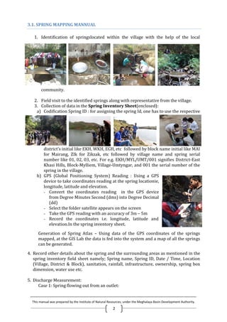
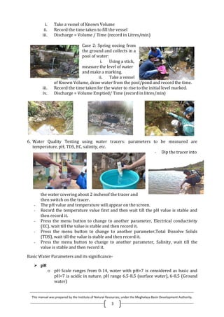

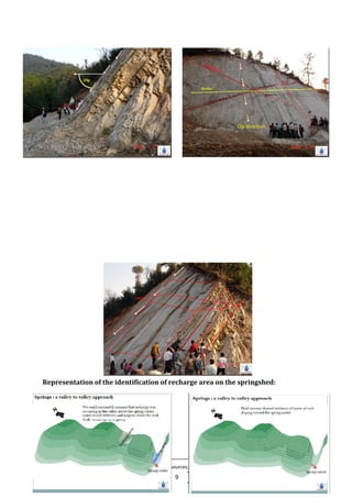
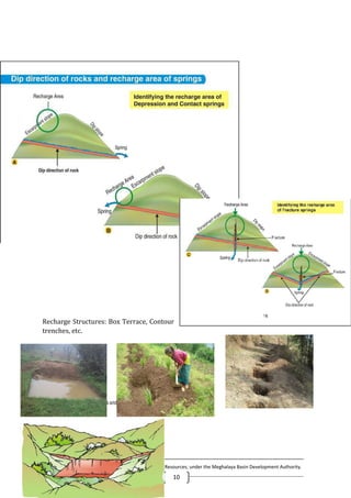
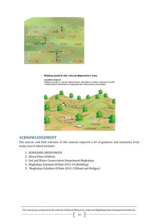


This manual provides a comprehensive guide on spring mapping and monitoring in Meghalaya, focusing on identifying springs with the local community and gathering essential data, including GPS coordinates and water quality measurements. It outlines procedures for discharge measurement, water quality testing, and the identification of geological features related to springs. Additionally, it emphasizes the importance of understanding different types of springs, their geological contexts, and the necessary tools for accurate data collection.