This document discusses different types of maps used in geology, including topographic maps, geologic maps, and subsurface maps. Topographic maps use contour lines to represent elevation changes on the earth's surface. Geologic maps represent the distribution of rock layers at the surface and include symbols to indicate strike and dip. Subsurface maps can be structural maps showing the elevation of subsurface rock layers, isopach maps showing thickness changes, or percentage maps. GPS technology is used to accurately locate points on maps.
Mechanism of Plate Tectonics and Resultant LandformsMithun Ray
Plate tectonics is a scientific theory that explains how major landforms are created as a result of Earth’s subterranean movements. The theory transformed the earth sciences by explaining many phenomena, including mountain building events, volcanoes, and earthquakes.
Artificial Recharge to Alluvial Aquifer, Northeastern Nuba Mountains, Sudan.IJRES Journal
Many engineering geology and structural geology aspects have been used in this study, to point out the suitability of the site for artificial recharge to alluvial aquifer, such as; rocks and soil types, seepage rate, structures and lineaments. The area is under lied by basement rocks with considerable thickness (10 to 15 m) of alluvial deposit. Overall soil type is sandy soil and its seepage rate is 34.56 Liter per hour. The most existing lineaments are trending toward NW direction while rocks foliation dipping toward WWN direction. The site is satisfied to be artificial recharge.
In this slide, the Framework of Petroleum Geology is discussed with the Pure Science such as Physics, Chemistry, and Biology.
Moreover, the composite relation is detailed with the initiative way to abandonment of the well.
Most Important factor, The Jobs crises is discussed !
Deprem Verilerinin H/V Oranının Mevsimsel Değişimi Ali Osman Öncel
H/V oranının zaman içinde değişimi konusu bana oldukça ilginç gelmişti ve bu tür bir çalışma yapıldı mı sorusunu netleştirmek için araştırma yaptım ve 2021 yılında bu konuda GJI gibi bir dergide yayınlanmış bir çalışma buldum. Bu çalışma oldukça iyi bir referans H/V çalışmaları için. Önemli referans düşünceler şöyle; 1) Mevsimsel olarak yağışa bağlı olarak yeraltı kaynaklarında ki azalma ve yükselmeye bağlı olarak H/V yükseliyor, 2) H/V pik değerleri kaya zemin üzerinde yaklaşık BİR (1) oranında seyreder ve PİK vermezken, kaya zeminden uzaklaşıldıkça zemin etkisi ile PİK değerleri değişir, 3) Deprem ve Gürültü sinyallerinden hesap edilen F(PİK) nerede ise sabitken, H/V oranları %10 değişir, 4) M6.8 büyüklüğünde meydana gelen bir deprem H/V değişimlerini etkiler.
Yapılan çalışmada kullanılan yaklaşım SESAME (2004) kriterlerine uygun olarak 1) 60 dakikalık veriler analizi, 2) 1000 günden fazla gözlem süresi 3) 10'dan fazla farklı zeminlerde istasyon 4) 60 dakikalık birbirinden ayrı verilerin analiz edilmesi. Oldukça emek yoğun bir çalışma
A graphic representation of the intersection of the geological bodies in the subsurface with a vertical plane of a certain orientation. It is a section of the terrain where the different types of rocks, their location, age, and composition, and the geometric relationship between them are represented. Which are made on the basis of geologic maps and data from geologic observations, mine works, boreholes, geophysical investigations, and so on.
Preparation of Geologic Sections:
1. Decide what the geologic cross section is going to be used for, and use this to guide you in selecting the appropriate scales.
2. Choose appropriate vertical and horizontal scales.
3. On the map, locate the well or borehole positions, land service elevations, depth of the well and the number of geologic units in each well bore.
4. Transfer the geologic information from each will long to the cross-section. This information represents discrete points of knowledge about the subsurface geology. Part of the geologist skills is interpretation from these discrete points of knowledge to those areas that lie in between. Part of this exercise is determining what units can be lumped together versus those which should be spit apart. Again, this mostly related to the data that is trying to be displayed.
5. Correlate the geologic information between boreholes. Applying knowledge of the specific deposition features of the rock or sediments can be used to increase the accuracy of the model. Look for differences in lithology, texture, or sediment or rock properties as a guide to defining contacts between contiguous geologic units. Use solid lines to indicate reasonably certain relations between discrete data points. Dashed lines are used to indicate uncertainty or inferred data. Areas where does not exist are typically labeled with question marks.
6. Incorporate Legend, Orientation, Title, and Scales to the cross-section. Ensure the units and use the same colour and pattern scheme as on the original geologic map.
Legend – the legend is a key to the patterns used to identify each unit on the cross-section. The units are ordered from oldest formation at the bottom of the legend to youngest unit at the top of the legend.
Orientation – the orientation of the cross-section is the direction that the cross-section line makes on Earth . You can indicate the orientation by writing the corresponding direction at each end of the cross-section (e.g., west and east).
Title – a descriptive title for the cross-section. You can include the letters used to identify the line on the original geological map in the title.
Scale – include a ratio scale and/or a bar scale to show the scale of the cross-section. The vertical and horizontal scales should be the same, so you only need to include one scale on the cross-section.
Strike and Dip Method
To measure and describe the geometry of geological layers, geologists apply the concepts of strike and dip.
•Strike refers to the line formed by the inte
Deadline is on Tuesday ,September 16 th2014I would like to .docxtheodorelove43763
Deadline is on Tuesday ,September 16 th/2014
I would like to have a design of the four broadcast protocols using a written description with the graphic representation showing how the design looks like and how information/communication happen between nodes beside the details explanation using scenarios to estimate the complexity.
Each of the designs should have an evaluation of the efficiency in the context of message complexity and round complexity.
The design should be based on a cube system with 8 nodes using
1. message-passing model
2. shared-memory model
3. mobile agent communication model
So the final work will have a total of 4 graphic designs with use case scenarios for each design to explain and calculate the complexity and efficiently of each design. The efficiency would be calculated for each design in term of message complexity and round complexity. Then decide on the best protocol among the proposed designs based on the efficiency.
geology2.pdf
geology1.pdf
1
Plate Tectonics Name: ________________
INTRODUCTION
Plate tectonics is a well established theory that unifies and provides a framework for
all geologic observations. Most geologic phenomenon observed near the Earth’s
surface are linked in some way to plate tectonic processes. The theory states that the
outer 60-100 km of the Earth is divided into slabs of rigid rock (the lithosphere). These
slabs (the plates) rest upon a semi-viscous layer of easily deformable rock (the
asthenosphere). Thermal convection within the asthenosphere pushes the plates in
horizontal directions at rates ranging from 1 cm to 12 cm/year. This causes the plates
to move in relation to one another. Boundaries between the 8 principle plates and
several smaller plates are zones of rock deformation, earthquakes and volcanism.
This lab utilizes real data that demonstrates and/or validates the theory of Plate
Tectonics. Four exercises, modified from Jones and Jones (2003), follow.
o Part A examines global maps of tectonic plate boundaries and earthquake data
to identify plate boundary locations and assess relative motion between the
plates.
o Part B uses maps of the ocean floor to calculate spreading rates across a mid-
oceanic ridge in the South Pacific.
o Part C interprets maps and utilizes geologic ages for Hawaiian Islands to better
understand movement of the underlying Pacific plate over a “hot spot”.
o Part D examines a geologic map along a portion of the San Andreas Fault to
evaluate the direction and rate of plate movement.
OBJECTIVES
Upon completion of this exercise, you will be able to understand:
1. basic differences between major types of plate boundaries.
2. magnetic stripping and use it to calculate spreading rates
3. the concept of “hot spots” and use this understanding to determine the speed
and direction of movement of plates
4. how to interpret a geological map of the San Andreas Fault and calculate the
rate of movement al.
A report that demonstrates the usefulness and viability of using digital image processing techniques to emphasise and describe geological, structural and topographical features captured from satellite imagery. With the use of ArcScene, ArcGIS and EDRAS Mapper.
The International Journal of Engineering & Science is aimed at providing a platform for researchers, engineers, scientists, or educators to publish their original research results, to exchange new ideas, to disseminate information in innovative designs, engineering experiences and technological skills. It is also the Journal's objective to promote engineering and technology education. All papers submitted to the Journal will be blind peer-reviewed. Only original articles will be published.
The papers for publication in The International Journal of Engineering& Science are selected through rigorous peer reviews to ensure originality, timeliness, relevance, and readability.
Coordinate system Geographical coordinate systemNaresh Kumar
UTm Universe transvers mercator, Geographic coordinate system
geoid, planar projection, cylindrical and conical projection, longitudinal, latitude, UTM zones 60 zones
Geologic maps show the distribution of rock units at the sur.pdfactivefiren
Geologic maps show the distribution of rock units at the surface as well as structural features,
such as faults and folds. A geologic map is usually printed on top of a regular topographic map
(the base map) to help you locate yourself on the map. The base map is printed with light colors,
so it doesn't interfere with seeing the geologic features on the map. The geology is represented by
colors, lines, and symbols unique to geologic maps. Each color used on a geologic map
represents a different geologic unit. A unit is a specific type of rock of a specific age range (for
example, a Permian limestone, a contact late Triassic sandstone, etc). All exposures of rocks of
the same age and type are shown with the same color and are separated from other rocks by a
line representing the contact between them. The two main types of contacts shown on most
geologic maps are depositional contacts and faults. Where the original depositional contact
between geologic units is preserved, it is shown on the geologic map as a thin line. If the rocks are
in contact because of a fault, a thicker line is used to represent the fault, and the relative motion
along the fault, if known, is indicated by labeling the upthrown side and downthrown side of the
fault. For low angle (thrust) faults the teeth are on the upthrown (hanging wall) block. Each
geologic unit is assigned a set of letters to symbolize it on the map. Usually the symbol is the
combination of a capital letter followed by one or more small letters. The capital letter represents
the age (geologic period) of the unit. Examples include Q (Quaternary), K (Cretaceous), and C
(Cambrian). The small letters indicate either the name of the unit, if it has one, or the type of rock,
if the unit has no name. Many geologic units are named based on where their characteristics are
bestdisplayed, or where they were first studied. For example, Jm is the map symbol for the
Morrison formation, a stratigraphic unit of Jurassic age first studied near Morrison, Colorado but
exposed throughout Colorado, Wyoming, and Utah (the Morrison formation is the source of many
dinosaur fossils). Js would be unnamed shale (s for shale) that is Jurassic in age. Sedimentary
rocks form in broad, flat layers (beds) that may later be tilted or bent by tectonic forces. The spatial
orientation of tilted rock layers is described in terms of strike and dip. Strike is the compass
direction of a line formed by the intersection of a horizontal plane (the surface of the Earth) and an
inclined surface (the titled rock layer). Dip is the angle between a horizontal plane and the inclined
surface and is always measured perpendicular to strike. On geologic maps " T " shaped-symbols
are used show the strike and dip of each rock unit. The top of the "T" is the line of strike and the
short arm of the " T " illustrates the dip direction in degrees. The higher the number, the steeper
the bed with 90 being perpendicular to the surface (vertical). In the example h.
sedimentary basin may be defined as an area of depression in the earth’s crust in which sediments accumulate during a particular time span at a significantly greater rate, and so to a significantly greater thickness.
The fundamental part of the trap which is low-permeable to impermeable rock with a capillary entry pressure large enough to prevent the petroleum from migrating further is termed as Seal.
The process of transportation of petroleum from its place of origin, the source rock, to its place of accumulation into the reservoir up to the trap is termed as Migration.
04. Historical development of petroleum geologySohail Nawab
In this Slide the History of Petroleum geology development is discussed that how oil is used from seepages and nowadays the techniques and advanced methods are being used to find out the reserves and to drill the reservoirs.
In this slide, the favorable environments of Hydrocarbon accumulation, Major occurrences, and detailed lecture has been done on where to look for Hydrocarbons is discussed.
In this slide basics of Petroleum GEOLOGY is illustrated with the little review of Petroleum and geology terminology.
Also, the responsibilities or role of petroleum Geology is elaborated.
Welcome to WIPAC Monthly the magazine brought to you by the LinkedIn Group Water Industry Process Automation & Control.
In this month's edition, along with this month's industry news to celebrate the 13 years since the group was created we have articles including
A case study of the used of Advanced Process Control at the Wastewater Treatment works at Lleida in Spain
A look back on an article on smart wastewater networks in order to see how the industry has measured up in the interim around the adoption of Digital Transformation in the Water Industry.
Water scarcity is the lack of fresh water resources to meet the standard water demand. There are two type of water scarcity. One is physical. The other is economic water scarcity.
Final project report on grocery store management system..pdfKamal Acharya
In today’s fast-changing business environment, it’s extremely important to be able to respond to client needs in the most effective and timely manner. If your customers wish to see your business online and have instant access to your products or services.
Online Grocery Store is an e-commerce website, which retails various grocery products. This project allows viewing various products available enables registered users to purchase desired products instantly using Paytm, UPI payment processor (Instant Pay) and also can place order by using Cash on Delivery (Pay Later) option. This project provides an easy access to Administrators and Managers to view orders placed using Pay Later and Instant Pay options.
In order to develop an e-commerce website, a number of Technologies must be studied and understood. These include multi-tiered architecture, server and client-side scripting techniques, implementation technologies, programming language (such as PHP, HTML, CSS, JavaScript) and MySQL relational databases. This is a project with the objective to develop a basic website where a consumer is provided with a shopping cart website and also to know about the technologies used to develop such a website.
This document will discuss each of the underlying technologies to create and implement an e- commerce website.
Overview of the fundamental roles in Hydropower generation and the components involved in wider Electrical Engineering.
This paper presents the design and construction of hydroelectric dams from the hydrologist’s survey of the valley before construction, all aspects and involved disciplines, fluid dynamics, structural engineering, generation and mains frequency regulation to the very transmission of power through the network in the United Kingdom.
Author: Robbie Edward Sayers
Collaborators and co editors: Charlie Sims and Connor Healey.
(C) 2024 Robbie E. Sayers
Industrial Training at Shahjalal Fertilizer Company Limited (SFCL)MdTanvirMahtab2
This presentation is about the working procedure of Shahjalal Fertilizer Company Limited (SFCL). A Govt. owned Company of Bangladesh Chemical Industries Corporation under Ministry of Industries.
Immunizing Image Classifiers Against Localized Adversary Attacksgerogepatton
This paper addresses the vulnerability of deep learning models, particularly convolutional neural networks
(CNN)s, to adversarial attacks and presents a proactive training technique designed to counter them. We
introduce a novel volumization algorithm, which transforms 2D images into 3D volumetric representations.
When combined with 3D convolution and deep curriculum learning optimization (CLO), itsignificantly improves
the immunity of models against localized universal attacks by up to 40%. We evaluate our proposed approach
using contemporary CNN architectures and the modified Canadian Institute for Advanced Research (CIFAR-10
and CIFAR-100) and ImageNet Large Scale Visual Recognition Challenge (ILSVRC12) datasets, showcasing
accuracy improvements over previous techniques. The results indicate that the combination of the volumetric
input and curriculum learning holds significant promise for mitigating adversarial attacks without necessitating
adversary training.
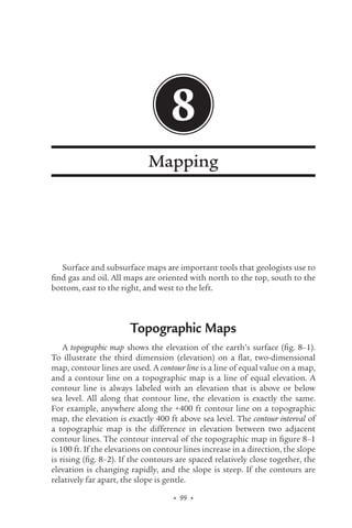
1. 99
• •
8
Mapping
Surface and subsurface maps are important tools that geologists use to
find gas and oil. All maps are oriented with north to the top, south to the
bottom, east to the right, and west to the left.
Topographic Maps
A topographic map shows the elevation of the earth’s surface (fig. 8–1).
To illustrate the third dimension (elevation) on a flat, two-dimensional
map, contour lines are used. A contour line is a line of equal value on a map,
and a contour line on a topographic map is a line of equal elevation. A
contour line is always labeled with an elevation that is above or below
sea level. All along that contour line, the elevation is exactly the same.
For example, anywhere along the +400 ft contour line on a topographic
map, the elevation is exactly 400 ft above sea level. The contour interval of
a topographic map is the difference in elevation between two adjacent
contour lines. The contour interval of the topographic map in figure 8–1
is 100 ft. If the elevations on contour lines increase in a direction, the slope
is rising (fig. 8–2). If the contours are spaced relatively close together, the
elevation is changing rapidly, and the slope is steep. If the contours are
relatively far apart, the slope is gentle.
08_Hyne.indd 99 1/25/12 10:52 AM
2. Nontechnical Guide to Petroleum Geology, Exploration, Drilling, and Production 3rd Edition
100
• •
Fig. 8–1. Land and a topographic map of the land
Fig. 8–2. Contoured topographic map
showing steep and gentle slopes
There are some important characteristics of contours on a topographic
map. Contour lines never cross. Contour lines are single lines; they never
branch. Contour lines are continuous; they always close or run off the map
and never end on the map.
Elevations can be accurately estimated from a topographic map. If a
point is on the +300 ft contour, it must be, by definition, exactly 300 ft
above sea level. If the point is about halfway between the +300 and +400
ft contour, an elevation of +350 ft is a good estimate. The shape of the
contours is characteristic for many topographic features such as hills,
ridges, and canyons.
A topographic map (or any contoured map) cannot be drawn without
some accurately surveyed points. After the elevations or values are located
on a map (spotted), contours can be drawn between the points. Contouring
08_Hyne.indd 100 1/25/12 10:52 AM
3. Chapter 8 Mapping
101
• •
of any map can be done either by hand or computer. The position of a
contour line between two data points can be accurately located by using
proportions. For example, the 400 contour line must run between data
points of 402 and 399 (fig. 8–3). A straight line is drawn between the two
data points. Because there is a difference of 3 between the data points (402
and 399), the line is divided into three equal segments. The 400 contour line
is located one segment from the 399 point and two segments from the 402
point. Anything that can be expressed by mathematics can be programmed
into a computer, and computer-generated contour maps can be made.
Fig. 8–3. Locating a contour using proportions
Geologic Maps
A geologic map (fig. 8–4) shows where each rock layer crops out on the
surface of the earth. Each rock layer is given a different pattern, color, and
symbol on the map. The basic sedimentary rock layer used for geologic
mapping is called a formation. A formation is a mappable rock layer
with a definite top and bottom. Geologists have divided all sedimentary
rocks into formations. Each formation has a two-part name. The first
part is a town where the layer crops out on the surface. The second part
is the dominant rock type, such as sandstone or limestone. San Andreas
Limestone, Bartlesville Sandstone, and Barnett Shale are formation names.
If the sedimentary rock layer is a mixture of rock types, such as alternating
thin sandstones and shales, the word formation is used, for example, the
Coffeyville Formation. Formations can be subdivided into smaller units
08_Hyne.indd 101 1/25/12 10:52 AM
4. Nontechnical Guide to Petroleum Geology, Exploration, Drilling, and Production 3rd Edition
102
• •
called members. A member is a distinctive but local bed in a formation
(fig. 8–5). It is also given a formal, two-part name. For example, the
Layton Sandstone Member is part of the Coffeyville Formation. Adjacent
formations of similar rocks can be joined to form a group and given a
geographic name (i.e., the Chase Group). If a rock layer occurs deep in the
subsurface and does not appear to crop out on the surface or if it is located
offshore, it is given a letter and number designation such as the H5 sands.
Fig. 8–4. Geologic map
Fig. 8–5. Stratigraphic column showing formations
and members
08_Hyne.indd 102 1/25/12 10:52 AM
5. Chapter 8 Mapping
103
• •
A geologic map is a flat, two-dimensional representation of the earth’s
surface. The orientation of rock layers, the third dimension, is shown with
a strike-and-dip symbol. Strike is the horizontal orientation of a plane (fig.
8–6a), such as a sedimentary rock layer or a fault. It is measured with a
compass orientation, such as north 30˚ east. Strike is shown as a short line
on the geological map (fig. 8–6b) that is oriented in the measured compass
direction. Dip is the direction and vertical angle of the plane. It is measured
perpendicular (90˚) to the strike (fig. 8–6a). The dip symbol on the map is
a small bar attached to the middle of the strike line (fig. 8–6b). It points in
the direction that the plane goes down into the earth. The angle in degrees
is often on the dip symbol. The dip of a rock layer is the angle and direction
it goes into the subsurface. Drilling updip means that the drillsite will be up
the angle (dip) of the rock layer from the last drillsite. Updip in a reservoir
is usually a favorable position from a dry hole (fig. 8–7). You may assume
that any reservoir rock is filled with water. Gas and oil are lighter than
water and will flow (migrate) updip in the reservoir rock to a high area.
One would almost never want to drill downdip from a dry hole; one would
want to drill updip.
a
b
Fig. 8–6. (a) Strike and dip of a sedimentary rock layer
and (b) strike-and-dip symbol on a geologic map
08_Hyne.indd 103 1/25/12 10:52 AM
6. Nontechnical Guide to Petroleum Geology, Exploration, Drilling, and Production 3rd Edition
104
• •
Updip
Updip
Fig. 8–7. Updip from a dry hole
A stratigraphic column (fig. 8–5) is a convenient method for presenting
the vertical sequence of rocks on a geologic map or in a basin. Any
deformation of the rocks, such as faulting or tilting, has been removed.
The youngest formation is at the top of the column, and the oldest is
located at the bottom. The column is drawn as a cliff of weathered rocks
with the weaker rock types (e.g., shales) indented. Stronger rock types (e.g.,
sandstones) protrude outward as they would weather in nature.
Common geological symbols (fig. 8–8) are used for rocks, structures,
and wells on a geological map.
Base Maps
A basemap is a map that shows the location of all the wells that have been
drilled in an area. Spotting a well involves locating a wellsite and placing the
well symbol (fig. 8–8) on a base map. Base maps can also include seismic
lines and other data.
08_Hyne.indd 104 1/25/12 10:52 AM
7. Chapter 8 Mapping
105
• •
Fig. 8–8. Common geological symbols
Global Positioning System
Accurate positioning is very important to geologists, geophysicists, and
petroleum engineers. They need to know the exact location of proposed
drillsites, existing wells, and seismic lines. These sites used to be located
with considerable time and expense using surveying tools. Since the 1980s,
accurate location in all weather and anywhere on the earth with no cost
has been determined by the Global Positioning System (GPS). GPS involves
the use of satellites and a receiver. There are 24 solar-powered satellites
very precisely orbiting the earth twice a day at an altitude of 12,550 miles
(20,200 km) in six planes with four satellites each. Each satellite transmits
extremely accurate time signals and the satellite’s orbital information. The
receiver at the location has an antenna tuned to each satellite’s frequency,
a processor, and a very stable clock. It compares the satellite time signal
08_Hyne.indd 105 1/25/12 10:52 AM
8. Nontechnical Guide to Petroleum Geology, Exploration, Drilling, and Production 3rd Edition
106
• •
with the same time on the receiver to determine how much time it took
the satellite signal to reach the receiver. It then uses that information
to compute the distance from the receiver to the satellite. By using the
computed distance from three, or more accurately from four satellites, the
location, usually in latitude and longitude, and the altitude of the receiver
are calculated and displayed on the receiver. Very precise receivers can
calculate positions to less than 10 ft (3 m) on average.
Subsurface Maps
Three important types of subsurface maps are structural, isopach,
and percentage. All three maps use contour lines to describe a subsurface
rock layer.
Structural map
A structural map uses contour lines to show the elevation of the top of a
subsurface sedimentary rock layer (fig. 8–9). The contour lines are usually
in minus feet below sea level, as most rocks are located below sea level. An
important structural map would be one contoured on the top of a potential
reservoir rock or drilling target.
Fig. 8–9. Structural map
08_Hyne.indd 106 1/25/12 10:52 AM
9. Chapter 8 Mapping
107
• •
Domes, anticlines, and faults can be identified on structural maps.
Both a hill on a topographic map and a dome on a structural map have a
bull’s eye pattern (fig. 8–10) with the highest elevation in the center. Both
a ridge on a topographic map and an anticline on a structural map have
a concentric but oblong pattern (fig. 8–11) with the highest elevation in
the center. Dip-slip faults are characterized by a rapid change in elevation
along a relatively straight line (fig. 8–12). A normal dip-slip fault that causes
a lost section in the rock layer being mapped (see fig. 5–18 in chapter 5) is
seen on the map as two lines separating the contour lines (fig. 8–13).
Fig. 8–10. Topographic map of a hill and structural map of a dome
08_Hyne.indd 107 1/25/12 10:52 AM
10. Nontechnical Guide to Petroleum Geology, Exploration, Drilling, and Production 3rd Edition
108
• •
Fig. 8–11. Topographic map of a ridge and structural map of an anticline
Fig. 8–12. Fault on a structural map
08_Hyne.indd 108 1/25/12 10:52 AM
11. Chapter 8 Mapping
109
• •
Fig. 8–13. Normal dip-slip fault on a structural map
Isopach map
An isopach map (fig. 8–14) uses contour lines to show the thickness of a
subsurface layer. If an oil or gas field has been drilled, an isopach map can
be made of the reservoir rock pay zone. The pay zone is the vertical distance
in a well that produces gas and/or oil. Grosspay contours the entire reservoir
thickness including nonproductive water-bearing and shaly zones. Net pay
contours only the productive thickness of the reservoir. A net pay isopach
map of a reservoir is used to calculate the oil and gas volume and reserves.
Fig. 8–14. Isopach map
08_Hyne.indd 109 1/25/12 10:52 AM
12. Nontechnical Guide to Petroleum Geology, Exploration, Drilling, and Production 3rd Edition
110
• •
An isopach map can be used in exploration to delineate a sandstone
pinch-out (fig. 8–15a) where the isopach contour line becomes zero. The
aerial patterns of beach and river channel sandstones are seen on an
isopach map (fig. 8–15b).
Fig. 8–15. Isopach map of (a) a sandstone pinch-out and (b)
a beach or river channel sandstone
An isopach map of a limestone layer can also be used to locate a reef. A
reef is a mound and is shown by thick contour lines (fig. 8–16). Barrier reefs
that are long (fig. 8–16a) can be distinguished from pinnacle reefs that are
circular (fig. 8–16b).
Fig. 8–16. Isopach map of (a) a barrier reef and
(b) a pinnacle reef
08_Hyne.indd 110 1/25/12 10:52 AM
13. Chapter 8 Mapping
111
• •
Percentage map
A percentage map (fig. 8–17) plots the percentage of a specific rock type
such as sandstone in a formation. Higher percentages of reservoir quality
rocks, such as sandstones and carbonates, imply a better reservoir quality.
Fig. 8–17. Sandstone percentage map of a formation composed
of sandstone and shale
08_Hyne.indd 111 1/25/12 10:52 AM