Downloaded 15 times

![Speed Control of Induction Machine with Reduction In Torque Ripple Using Robust Space-
Vector Modulation DTC Scheme
http://www.iaeme.com/IJARET/index.asp 79 editor@iaeme.com
Figure.1, thereby introducing fast torque dynamics response in comparison with the
field oriented vector control technique. However, this conventional DTC approach has
some disadvantages such as; high torque ripple and variable switching frequency,
which is varying with speed, load torque and the selected hysteresis bands. On the
other hand to reduce the torque ripple; the hysteresis torque and flux controller bands
must be reduced to match the required torque performance, which requires reduction
of the system sampling time and it is necessary to use a very fast processing
controller. Although the system sampling frequency can be increased in the
conventional DTC the inverter switching frequency is still low, approximately less
than one third of the sampling frequency [1, 2]. The inverter switching frequency can
be increased using a dithering signal, by adding a limited amplitude high frequency
signal to the torque and flux error signals [3]. Although the switching frequency is
increased it is still variable for small error bands. Other research concerns with these
disadvantages using multilevel inverter, there are more voltage space vectors
available to control the flux and torque [4]. However, these approaches require more
power devices, which increase the cost of the system and make it more complex. In
[5, 6] discrete space vector modulation DTC approach is used to reduce the torque
ripple. However, there is a complexity of selecting the additional hysteresis
controllers. On the other hand, space vector modulation (SVM) modulator is
incorporated with direct torque control for Induction Motor drives to provide a
constant inverter switching frequency and low torque ripple, a predictive PI controller
is used to calculate the command voltage vector [7].
In this paper, a new and simple DTC algorithm with fixed switching frequency for
Induction Motor is proposed to reduce the torque ripples. The well-developed SVM
technique is applied to inverter control in the proposed DTC-based Induction Motor
drive system, thereby dramatically reducing the torque ripples. The simulation results
are carried out by modelling the drive systems using a Matlab/Simulink.
2. CLASSICAL DIRECT TORQUE CONTROL (DTC)
OPERATION.
The block diagram of classical DTC proposed by I. Takahashi and T. Nogouchi is
presented in Figure.1.
Figure 1 Block Diagram of Classical-DTC](https://image.slidesharecdn.com/ijaret0702008-160730104807/85/SPEED-CONTROL-OF-INDUCTION-MACHINE-WITH-REDUCTION-IN-TORQUE-RIPPLE-USING-ROBUST-SPACE-VECTOR-MODULATION-DTC-SCHEME-2-320.jpg)
![Yeshoda Harish Kumar and Vishnu Goyal
http://www.iaeme.com/IJARET/index.asp 80 editor@iaeme.com
The stator flux amplitude and the electromagnetic torque are the reference
signals which are compared with the estimated values respectively. The
flux and torque errors are delivered to the hysteresis controllers. The digitized output
variables and the stator flux position sector selects the appropriate voltage vector from
the switching table. Thus, the selection table generates pulses to control the power
switches in the inverter.
The stator flux vector and the torque produced by the motor can be estimated
respectively. These equations only require the knowledge of the previously applied
voltage vector Vs, measured stator current Is, stator resistance Rs, and the motor poles
number p [5].
The components of stator flux are given by:
(1)
(2)
The magnitude of the stator flux can be estimated by:
(3)
The flux vector zone can be obtained using the stator flux components. The
electromagnetic torque can be calculated by:
(4)
For the flux is defined two-level hysteresis controller and for the torque three-
level hysteresis controller is used.
The output signals are defined as:
Where is the total hysteresis bandwidth of the controller. The actual stator
flux is constrained within the hysteresis band and tracks the command flux. The
torque control loop has three levels of digital output represented by the following
conditions.
The above considerations allow construction of the selection table as presented in
below Table-1.
Table I Switching Scheme of Basic-DTC
S(1) S(2) S(3) S(4) S(5) S(6)
1
1
0
-1
-1
1
0
-1](https://image.slidesharecdn.com/ijaret0702008-160730104807/85/SPEED-CONTROL-OF-INDUCTION-MACHINE-WITH-REDUCTION-IN-TORQUE-RIPPLE-USING-ROBUST-SPACE-VECTOR-MODULATION-DTC-SCHEME-3-320.jpg)
![Speed Control of Induction Machine with Reduction In Torque Ripple Using Robust Space-
Vector Modulation DTC Scheme
http://www.iaeme.com/IJARET/index.asp 81 editor@iaeme.com
The classical DTC method can be characterized as follows:
Advantages: simple structure, no coordinate transformation, no separate voltage
modulation block, no current control loops, very good flux and torque dynamic
performance,
Disadvantages: Variable switching frequency, problems during starting and low
speed operation, high torque ripples, flux and current distortion caused by stator flux
vector sector position change and high sampling frequency is required for digital
implementation.
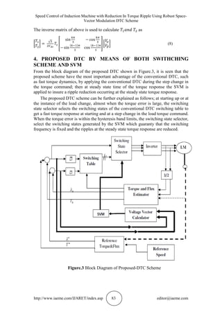
3. DTC-SVM SCHEME
In the DTC-SVM system, the same flux and torque estimator which is used for the
conventional DTC is still used in the proposed DTC scheme as shown in Figure.2.
Instead of the switching table and hysteresis controllers, an optimal voltage vector
calculator is used to calculate the reference voltage vector as a function of the torque
and flux errors. The applied voltage vectors and their duration times are selected and
calculated using the SVM modulator. From the block diagram of the DTC-SVM
shown in Fig.4, it is seen that this scheme have the most important advantage over
conventional DTC, such as at steady state time of the torque response the SVM is
applied to insure a ripple reduction occurring at the steady state torque response[7].
Figure 2 Block Diagram of DTC-SVM Scheme
The procedure for implementing a two-level space vector PWM can be summarized
as follows:
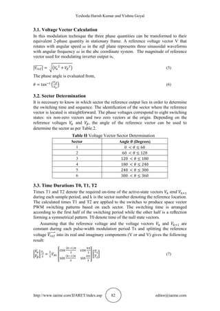
1. Calculate the angle and reference voltage vector based on the input voltage
components.
2. Find the sector in which lies and the adjacent space vectors of Vk and Vk + 1
based on the sector angle .
3. Find the time intervals , and the angle .](https://image.slidesharecdn.com/ijaret0702008-160730104807/85/SPEED-CONTROL-OF-INDUCTION-MACHINE-WITH-REDUCTION-IN-TORQUE-RIPPLE-USING-ROBUST-SPACE-VECTOR-MODULATION-DTC-SCHEME-4-320.jpg)
![Yeshoda Harish Kumar and Vishnu Goyal
http://www.iaeme.com/IJARET/index.asp 84 editor@iaeme.com
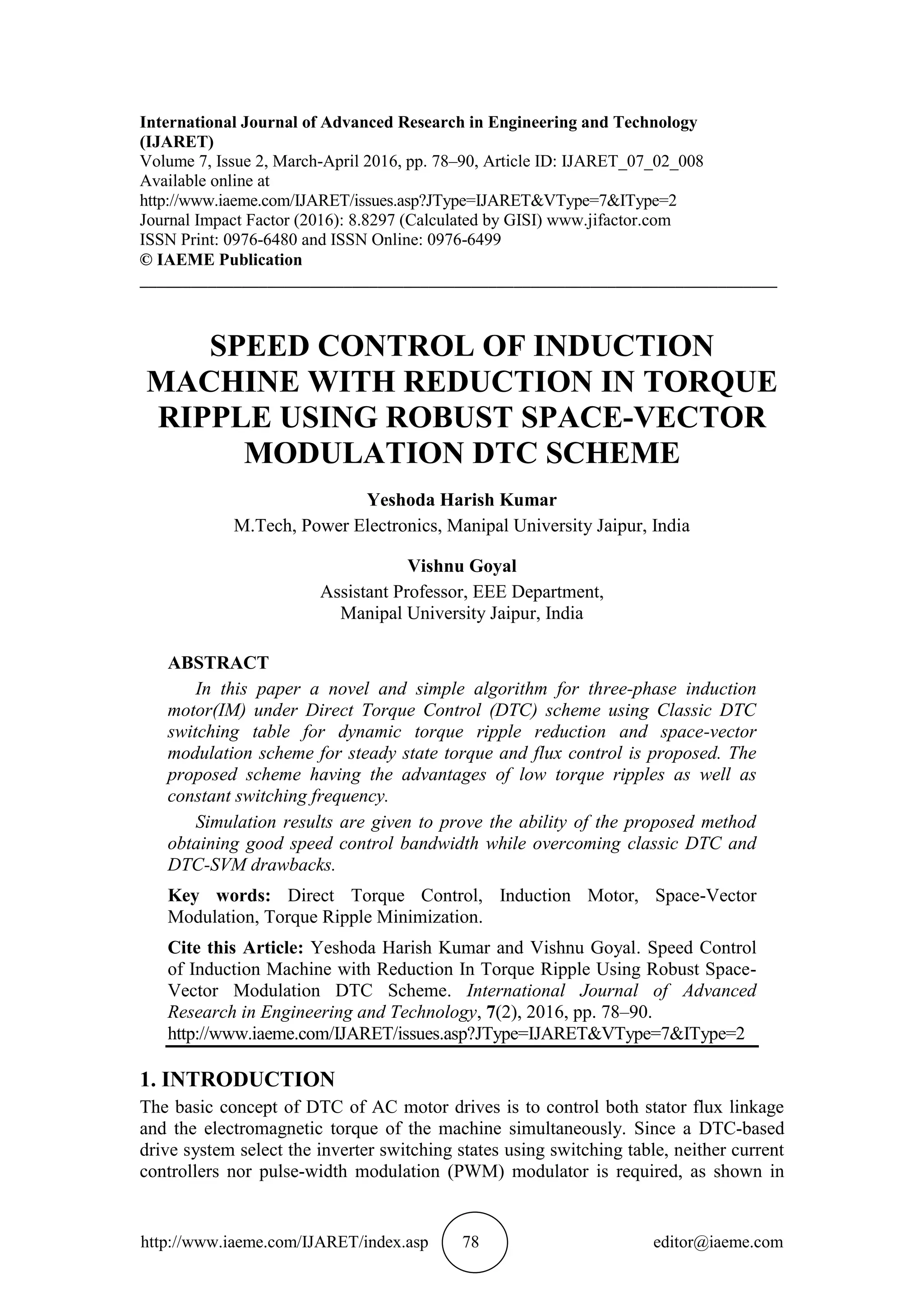
5. SIMULATION RESULTS
The system performance under the proposed DTC strategy is evaluated, and the
results are compared with the results obtained by the conventional DTC and DTC-
SVM schemes. MATLAB/SIMULINK models were developed to examine the
conventional and the proposed DTC algorithms. In simulation, the sampling time is
20 µs for both the conventional and proposed DTC schemes and the switching time
for the proposed DTC is 100 µs. The switching table used in [1] is employed for the
conventional DTC. The switching delays and the forward drop of the power switches,
the dead time of the inverter and the non-ideal effects of the Induction motor are
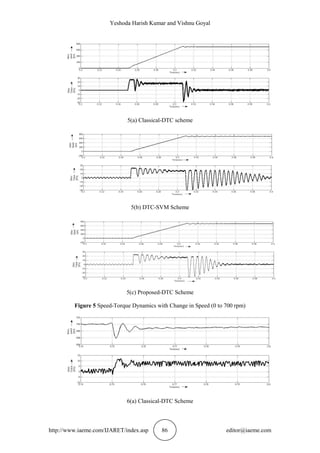
neglected in the models. The torque dynamics performances of the conventional and
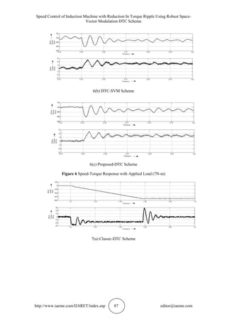
proposed DTC schemes at 700 rpm are compared as shown in Figure.5 under the
same operation conditions. It is seen that the torque ripple is reduced by more than 50
% at no-load and load conditions in the proposed DTC.
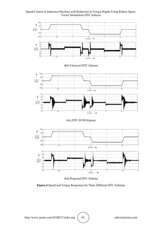
The speed and torque response for the classical DTC algorithm is given in Fig. 4
(b) and the Fig. 4 (c) show the torque response for the DTC algorithm with DTC-
SVM Scheme, and finally the proposed DTC algorithm torque response is given in
Fig. 4 (d). It can be seen from the figure that the proposed DTC has achieved a fast
speed response than that for the conventional DTC. The speed dynamic response and
their corresponding torque response for three algorithms more declaration is shown in
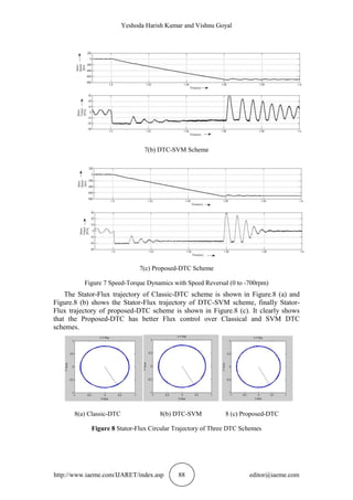
Figure.5 and Figure.7. It is seen that the torque ripple reduction is still valid at low
and high speed ranges. A speed reverse dynamics is carried out at two different speed
references, +700 rpm and -700 rpm, to indicate the validity of the controller operation
at both speed directions. The simulation results for the speed reversing dynamics are
shown in Figure.7.
Also a comparative simulation results between the proposed DTC algorithm and
other algorithms are shown in Figure.5 and Figure.6, where a reference speed of 700
rpm is applied to the motor then, a load torque of 7 Nm is applied at t = 0.75 sec.
4(a) Reference Speed and Load Torque](https://image.slidesharecdn.com/ijaret0702008-160730104807/85/SPEED-CONTROL-OF-INDUCTION-MACHINE-WITH-REDUCTION-IN-TORQUE-RIPPLE-USING-ROBUST-SPACE-VECTOR-MODULATION-DTC-SCHEME-7-320.jpg)
![Yeshoda Harish Kumar and Vishnu Goyal
http://www.iaeme.com/IJARET/index.asp 90 editor@iaeme.com
APPENDIX
Parameters of the used Induction Machine are given in below Table.3.
Table III Induction Motor Parameters
Nominal Power 4000W
Frequency 50Hz
Number of Pole Pairs 2
Stator Resistance 1.405ohm
Rotor Resistance 1.395ohm
Stator Inductance 5.839mH
Rotor Inductance 5.839mH
Mutual Inductance 172.2mH
REFERENCES
[1] L.Zhong, and M.F.Rahman, "Analysis of direct torque control in permanent
magnet synchronous motor drives," IEEE Trans. Power Elec., Vol. 12, No. 3,
May 1997.
[2] S. Dan, F.Weizhong, and H.Yikang, "Study on the direct torque control of
permanent magnet synchronous motor drives," 5th International Conference
on Electrical Machines, ICEMS, 2001.
[3] T. Noguchi, M. Yamamoto, S. Kondo, I. Takahashi, "Enlarging switching
frequency in direct torque controlled inverter by means of dithering," IEEE
Transaction on Industry Applications,1999.
[4] L.X.Tang, M.F.Rahman, Y.Zhiqing, and T.Cun, "In-depth research on direct
torque control of permanent magnet synchronous motor," IECON 02
Industrial Electronics Society, IEEE 28th
annual Conference, 2002.
[5] Brahim Metidji, Lotfi Baghli, and Seddik Bacha, “Low-Cost Direct Torque
Control Algorithm for Induction Motor without AC Phase Current Sensors”,
IEEE Transactions on Power Electronics, Vol.27.No.9, September 2012.
[6] M.Ramaprasad Reddy, T.Brahmananda Reddy and B.Brahmaiah,” discrete
Space Vector Modulation Algorithm Based Vector Controlled Induction
Motor Drive”, Journal of Electrical Engineering.
[7] D.A. Shahakar. Optimum Design Approach of Switched Reluctance Motors
by Torque Ripple Reduction. International Journal of Advanced Research in
Engineering and Technology, 5(4), 2014, pp. 190–197.
[8] Pradeep B Jyoti, J.Amarnath and D.Subbarayudu. Application of Neuro-
Fuzzy Controller In Torque Ripple Minimization of Vector Controlled Vsi
Induction Motor Drive. International Journal of Electrical Engineering and
Technology, 4(3), 2012, pp. 121–127.
[9] Hussain Shaik, S.Chaitanya and Dr. Sardar Ali. Speed Estimation Error of
Sensorless Induction Motor Drives Using Soft Computing Technique.
International Journal of Advanced Research in Engineering and Technology,
4(2), 2013, pp. 13–19.
[10] Anjana Manuel and Jebin Francis,” Simulation of Direct Torque Controlled
Induction Motor Drive by Using Space Vector Pulse Width Modulation for
Torque Ripple Reduction”, IJAREEIE Vol.2, Isuue.9, September 2013.](https://image.slidesharecdn.com/ijaret0702008-160730104807/85/SPEED-CONTROL-OF-INDUCTION-MACHINE-WITH-REDUCTION-IN-TORQUE-RIPPLE-USING-ROBUST-SPACE-VECTOR-MODULATION-DTC-SCHEME-13-320.jpg)

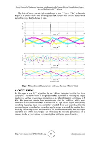
This paper presents a novel direct torque control (DTC) scheme for three-phase induction motors aimed at reducing torque ripple while maintaining a constant switching frequency. The proposed method combines classic DTC with space-vector modulation (SVM), showing improved speed control and performance compared to traditional DTC methods. Simulation results demonstrate a significant reduction in torque ripples and a robust control of machine flux, validating the effectiveness of the new algorithm.