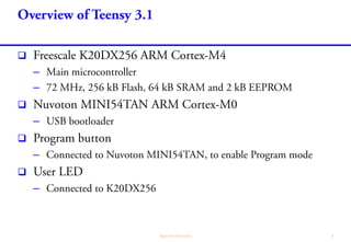
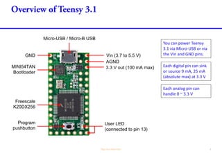
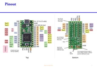
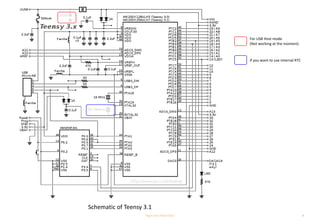
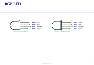
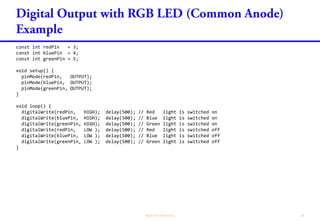
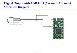
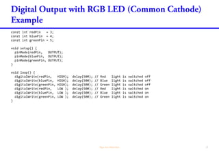
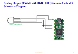
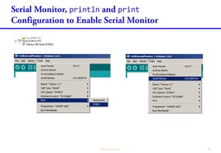
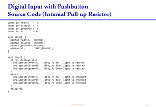
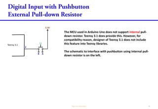
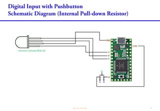
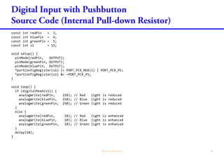
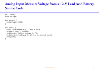
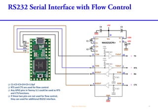
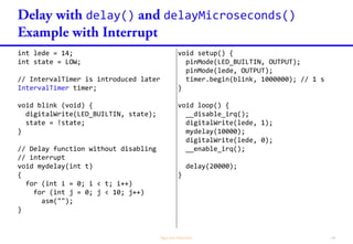
The document provides information about interfacing a Teensy 3.1 microcontroller board with various external components like LEDs, pushbuttons, DC motors, and batteries. It includes code examples for blinking an LED, controlling an RGB LED, reading a pushbutton, and measuring battery voltage. Circuit diagrams are presented for connecting components like LEDs, motors, and batteries to the Teensy. The document also discusses using the Teensy's I/O pins, analog inputs, and serial communication.


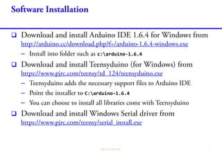
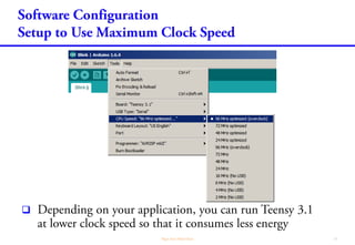

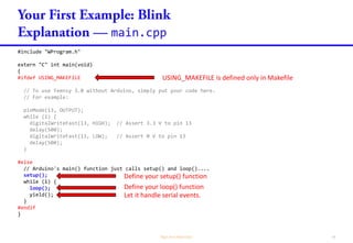


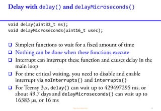
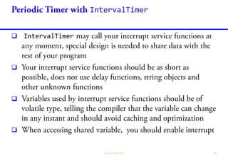
![println print
long count = 0;
char buff[80];
void increase() {
count++;
}
void setup() {
Serial.begin(38400);
}
void loop()
{
snprintf(buff, 80, "Hello World - %ld", count);
increase();
Serial.println(buff);
delay(1000);
}
print() does not print NEWLINE.](https://image.slidesharecdn.com/teensyupandrunning2-150919031404-lva1-app6891/85/Up-and-running-with-Teensy-3-1-39-320.jpg)


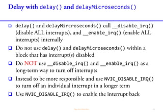
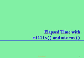
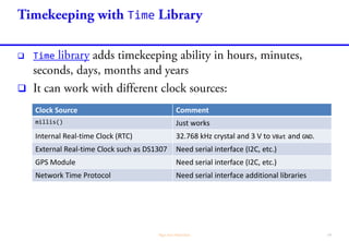
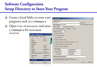
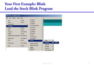
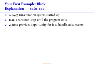
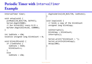
![millis() micros()
char strbuf[48];
void setup(){
Serial.begin(9600);
}
void loop(){
snprintf(strbuf, 48,
"Time: %ld ms (%ld µs)",
millis(), micros()
);
Serial.println(strbuf);
delay(1000);
}](https://image.slidesharecdn.com/teensyupandrunning2-150919031404-lva1-app6891/85/Up-and-running-with-Teensy-3-1-70-320.jpg)
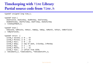
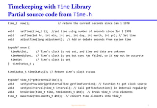
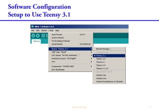
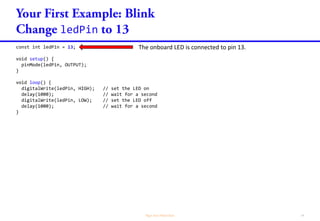
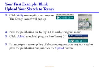
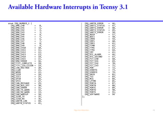
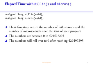
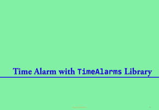
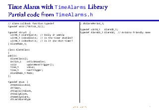
![Time
millis()
// The time is set by program. This information
// is lost once the power is removed.
#include <TimeLib.h>
// weekday() returns integer: 1 = Sunday
const char *WeekdayName[] = {
" " , // 0
"Sunday" , // 1
"Monday" , // 2
"Tuesday" , // 3
"Wednesday", // 4
"Thursday" , // 5
"Friday" , // 6
"Saturday" // 7
};
// month() returns integer: 1 = January
const char *MonthName[] = {
" ", // 0
"Jan", // 1
"Feb", // 2
"Mar", // 3
"Apr", // 4
"May", // 5
"Jun", // 6
"Jul", // 7
"Aug", // 8
"Sep", // 9
"Oct", // 10
"Nov", // 11
"Dec" // 12
};
char datetime[32];
void setup() {
// Set system time to 23:59:50 31-12-1999
setTime(23, 59, 50, 31, 12, 1999);
}
void loop() {
snprintf(datetime, 32,
"%02d:%02d:%02d %02d-%s-%d %s",
hour(), minute(), second(),
day(), MonthName[month()],
year(), WeekdayName[weekday()]
);
Serial.println(datetime);
delay(1000);
}](https://image.slidesharecdn.com/teensyupandrunning2-150919031404-lva1-app6891/85/Up-and-running-with-Teensy-3-1-77-320.jpg)

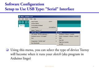
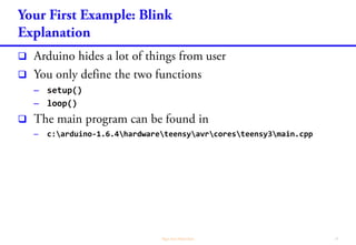
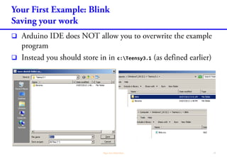
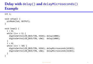
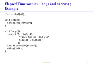
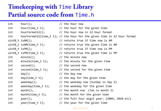
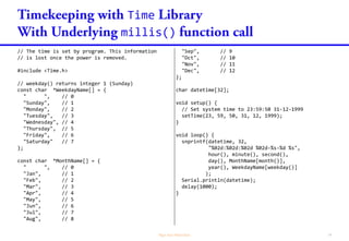
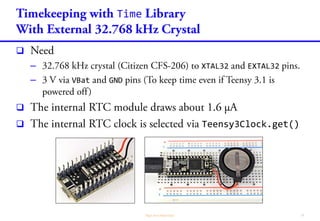
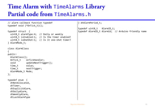
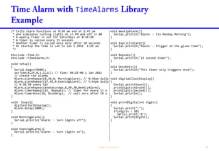
![Time
// The time is set by program and is fixed.
// The time continue from there onwards.
// The RTC module is powered by a 3 V battery and
// oscillated by an external 32.768 Hz crystal.
// Timekeeping continues once the power is removed.
#include <TimeLib.h>
// weekday() returns integer 1 (Sunday)
const char *WeekdayName[] = {
" ", // 0
"Sunday", // 1
"Monday", // 2
"Tuesday", // 3
"Wednesday", // 4
"Thursday", // 5
"Friday", // 6
"Saturday" // 7
};
// month() returns integer: 1 = January
const char *MonthName[] = {
" ", // 0
"Jan", // 1
"Feb", // 2
"Mar", // 3
"Apr", // 4
"May", // 5
"Jun", // 6
"Jul", // 7
"Aug", // 8
"Sep", // 9
"Oct", // 10
"Nov", // 11
"Dec" // 12
};
char datetime[32];
time_t getTeensy3Time()
{
return Teensy3Clock.get();
}
void setup() {
setSyncProvider(getTeensy3Time);
// Set system time to 23:59:50 31-12-1999
setTime(23, 59, 50, 31, 12, 1999);
}
void loop() {
snprintf(datetime, 32,
"%02d:%02d:%02d %02d-%s-%d %s",
hour(), minute(), second(),
day(), MonthName[month()],
year(), WeekdayName[weekday()]
);
Serial.println(datetime);
delay(1000);
}](https://image.slidesharecdn.com/teensyupandrunning2-150919031404-lva1-app6891/85/Up-and-running-with-Teensy-3-1-79-320.jpg)
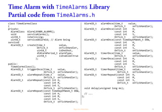
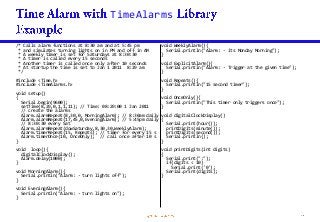
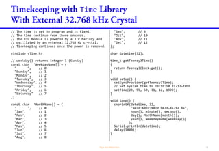
![TimeAlarms
TimeAlarms.h
class TimeAlarmsClass
{
private:
AlarmClass Alarm[dtNBR_ALARMS];
void serviceAlarms();
uint8_t isServicing;
uint8_t servicedAlarmId; // Alarm being
serviced
AlarmID_t create(time_t value,
OnTick_t onTickHandler,
uint8_t isOneShot,
dtAlarmPeriod_t alarmType,
uint8_t isEnabled=true
);
public:
TimeAlarmsClass();
AlarmID_t triggerOnce(time_t value,
OnTick_t onTickHandler);
AlarmID_t alarmRepeat(time_t value,
OnTick_t onTickHandler);
AlarmID_t alarmRepeat(const int H,
const int M,
const int S,
OnTick_t onTickHandler);
AlarmID_t alarmRepeat(const timeDayOfWeek_t DOW,
const int H,
const int M,
const int S,
OnTick_t onTickHandler);
AlarmID_t alarmOnce(time_t value,
OnTick_t onTickHandler);
AlarmID_t alarmOnce(const int H,
const int M,
const int S,
OnTick_t onTickHandler);
AlarmID_t alarmOnce(const timeDayOfWeek_t DOW,
const int H,
const int M,
const int S,
OnTick_t onTickHandler);
AlarmID_t timerOnce(time_t value,
OnTick_t onTickHandler);
AlarmID_t timerOnce(const int H,
const int M,
const int S,
OnTick_t onTickHandler);
AlarmID_t timerRepeat(time_t value,
OnTick_t onTickHandler);
AlarmID_t timerRepeat(const int H,
const int M,
const int S,
OnTick_t onTickHandler);
void delay(unsigned long ms);
// ...
};](https://image.slidesharecdn.com/teensyupandrunning2-150919031404-lva1-app6891/85/Up-and-running-with-Teensy-3-1-87-320.jpg)