This document describes a project to design and implement an induction motor drive. It includes:
1. A list of group members and project details for contacting them.
2. An outline of the report sections covering the variable frequency drive, components, product ratings, block and schematic diagrams, app development, and output results.
3. Descriptions of the components used, including an Arduino, MOSFET board, capacitor bank, transformer, diodes, heat sinks, Bluetooth module, and induction motor. Testing of components, circuit prototyping, and app interfacing with Arduino is mentioned as work completed.
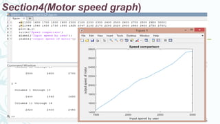
4. Pictures show the results of rectification, PWM signals, output sine waves