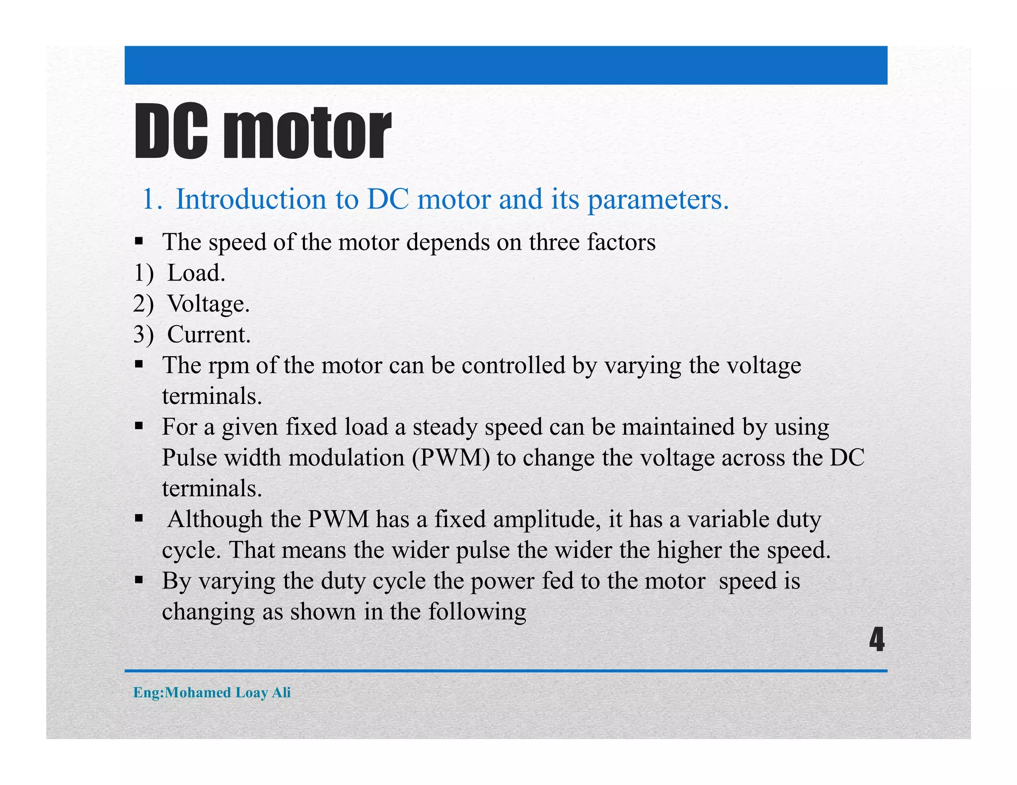
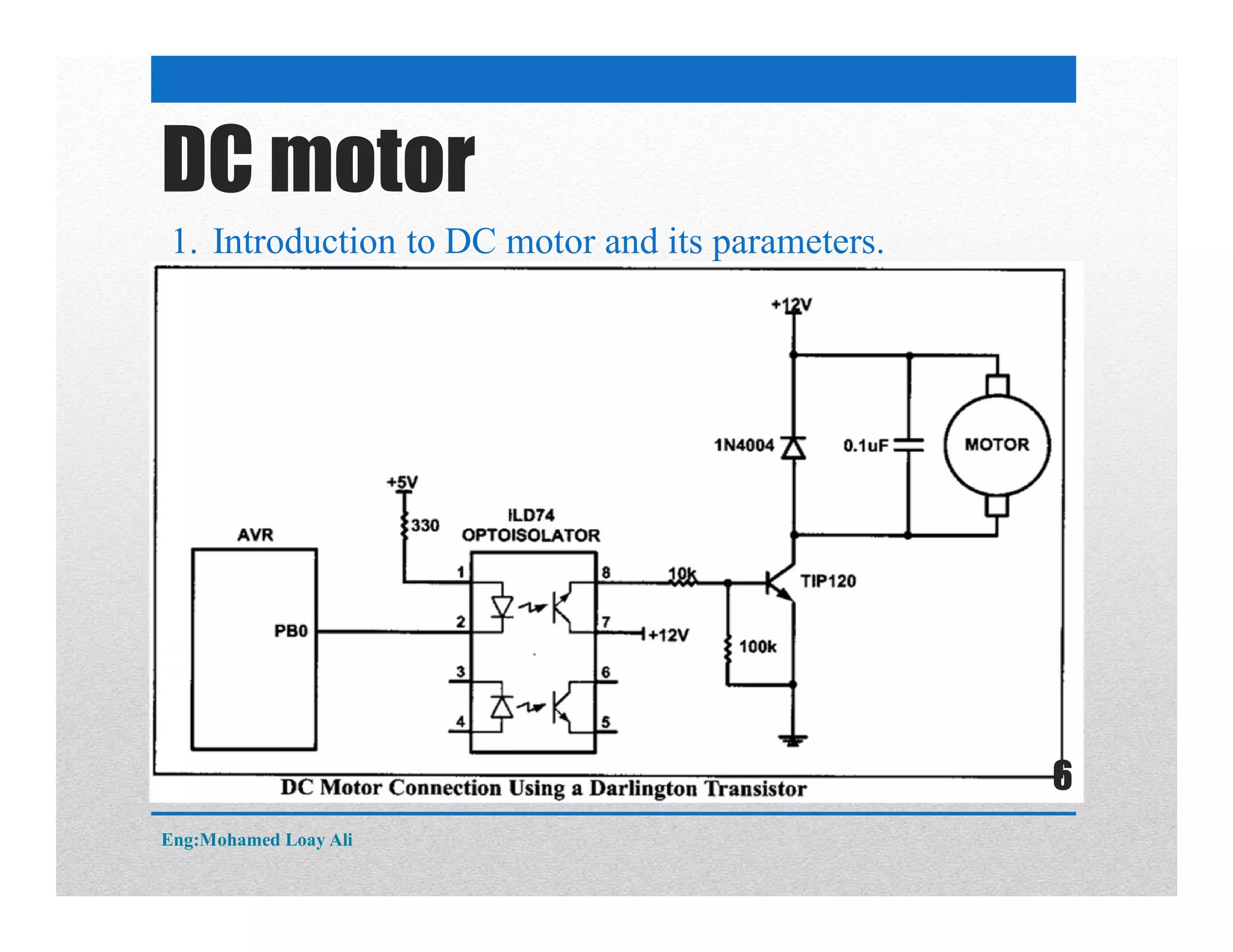
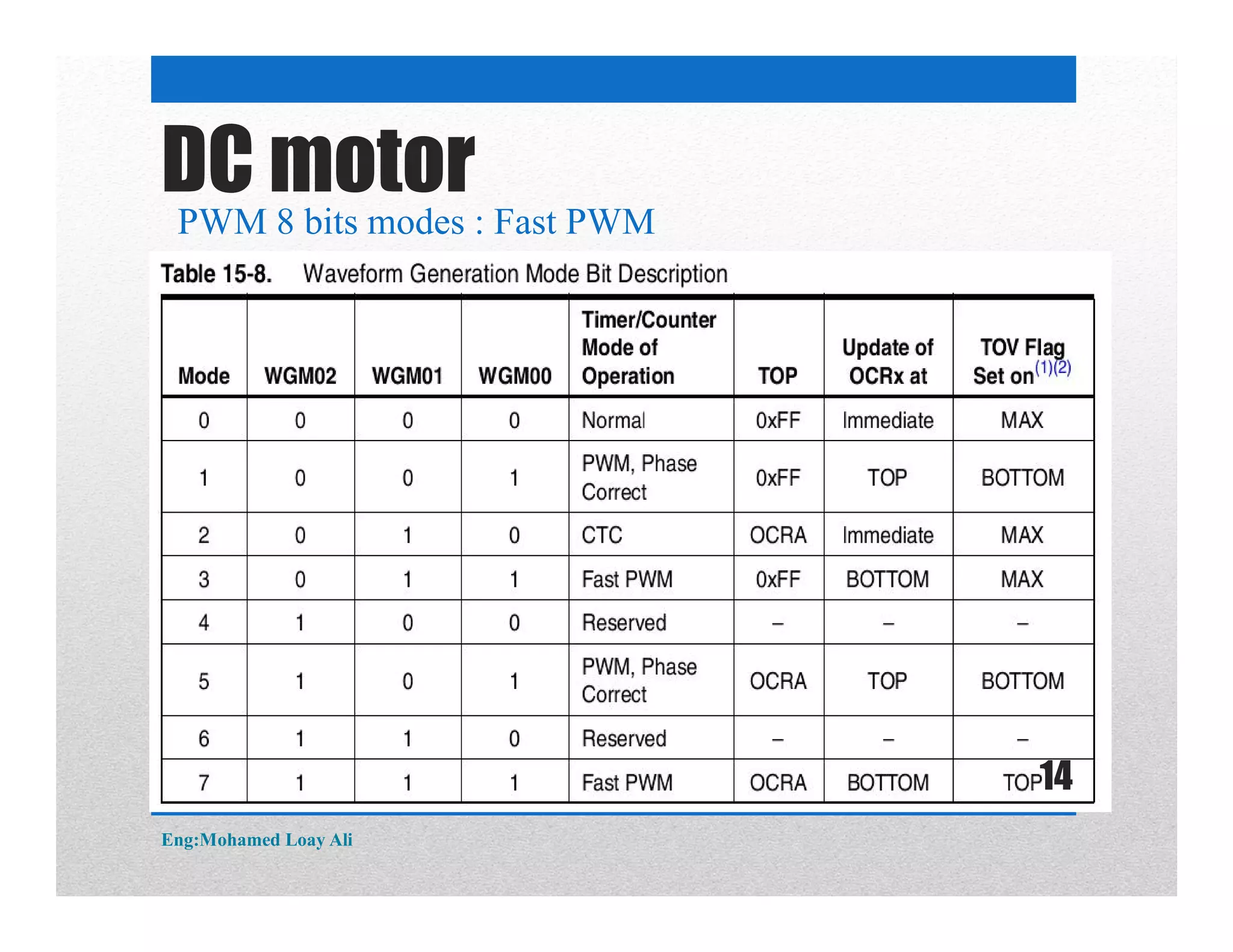
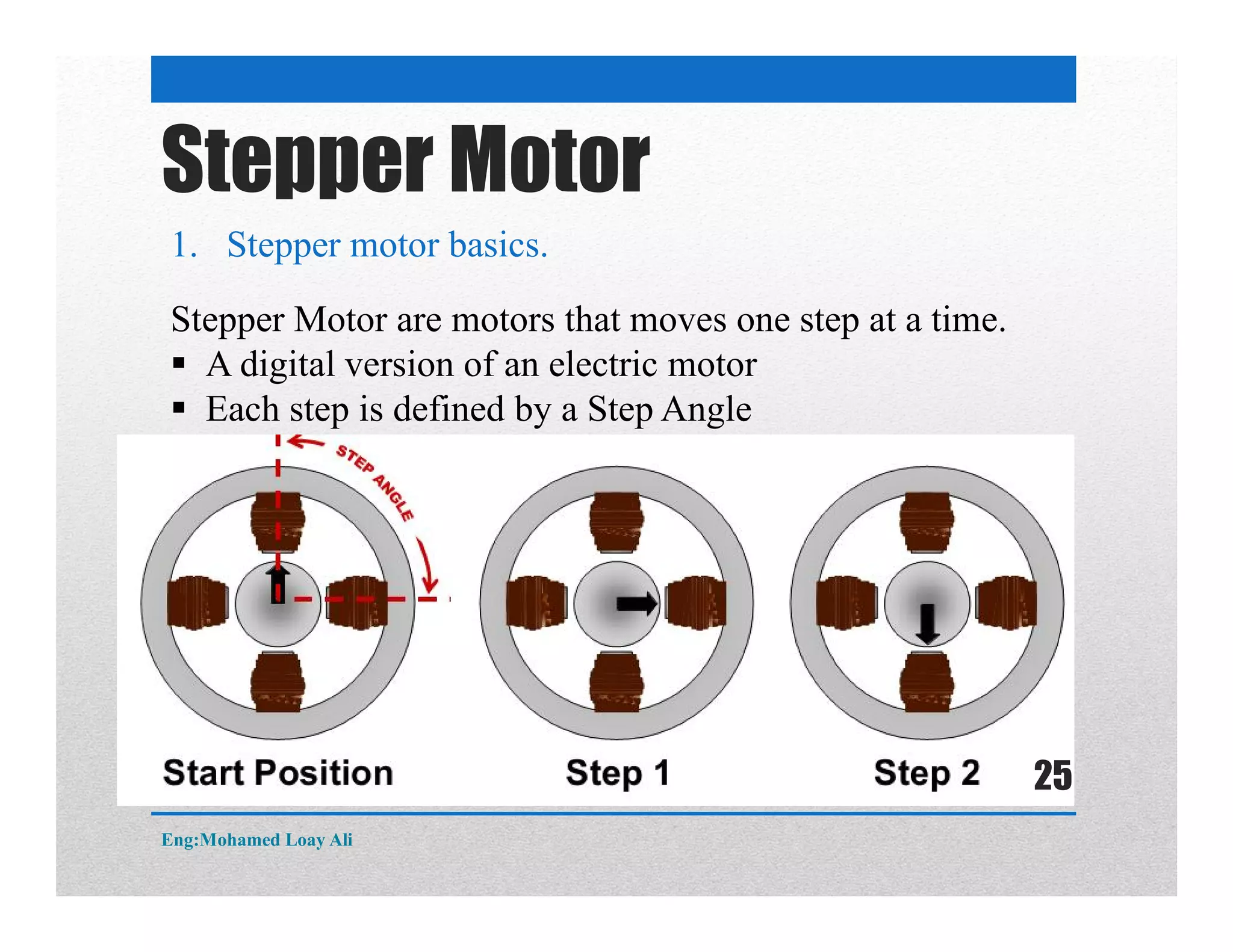
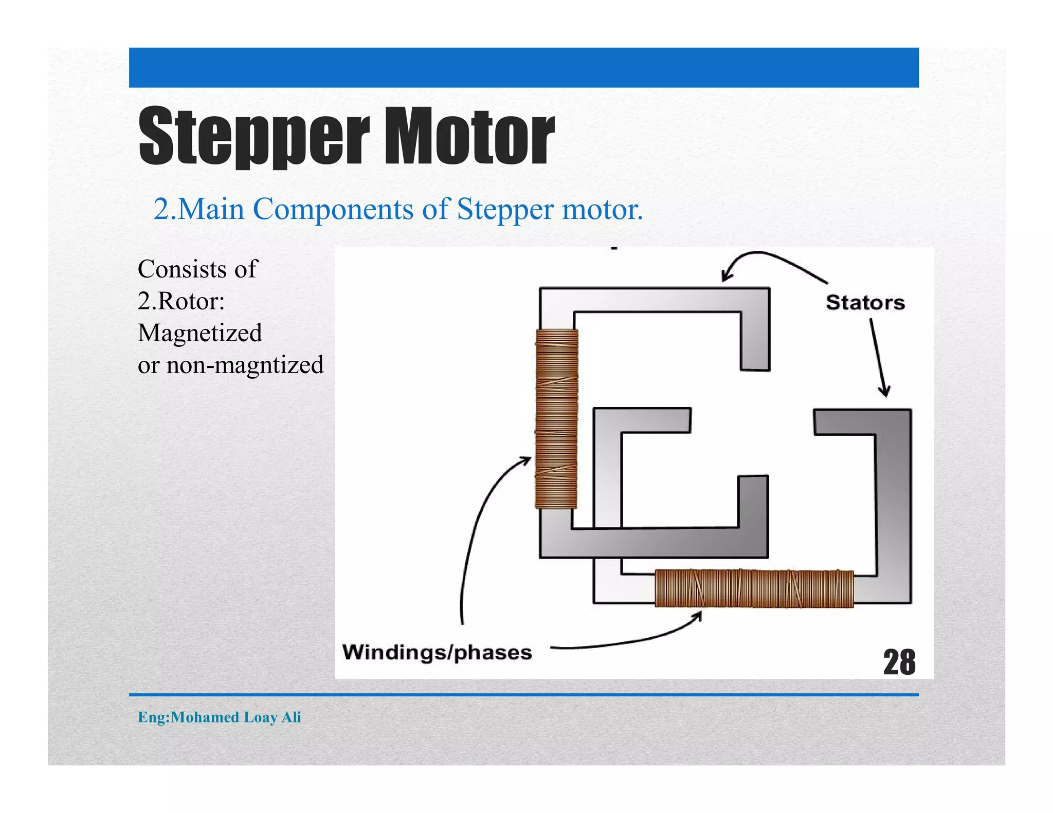
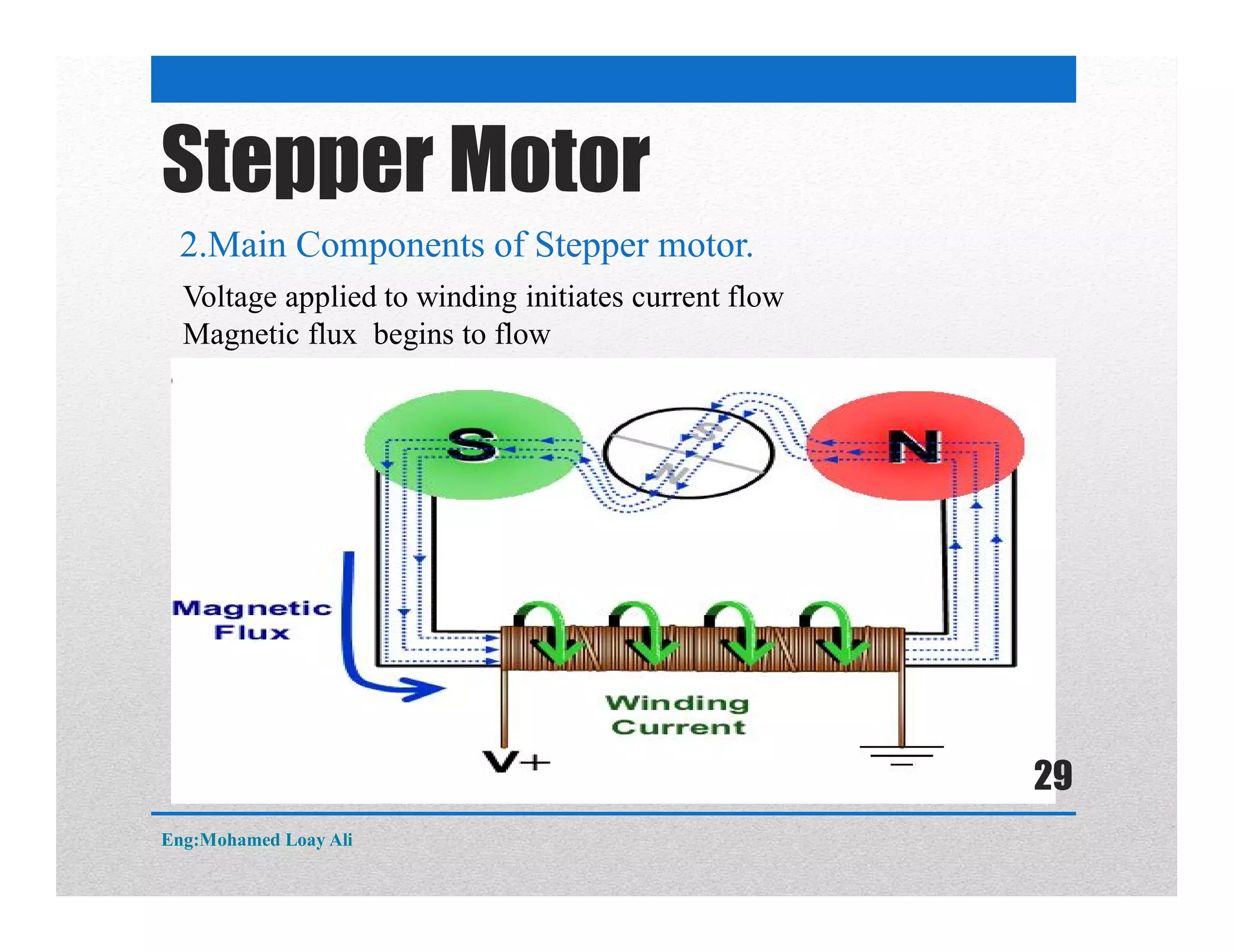
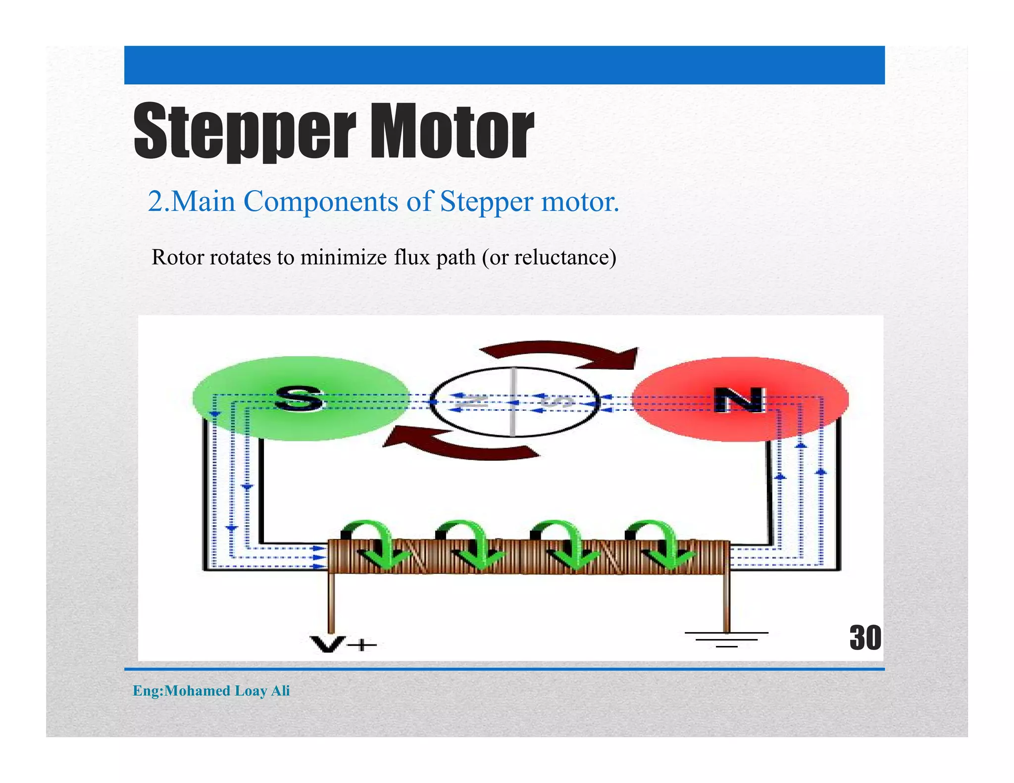
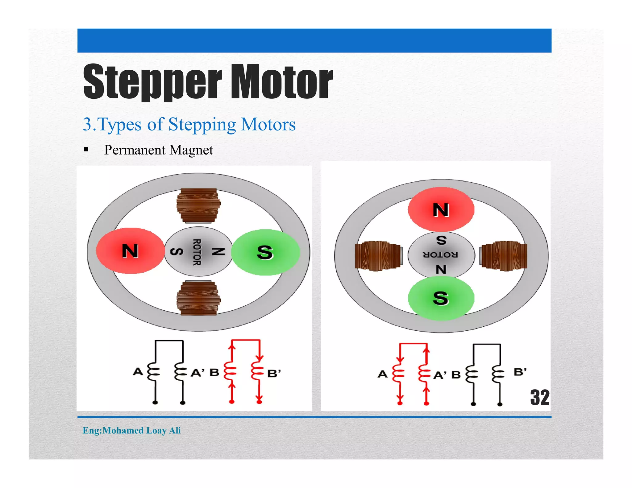
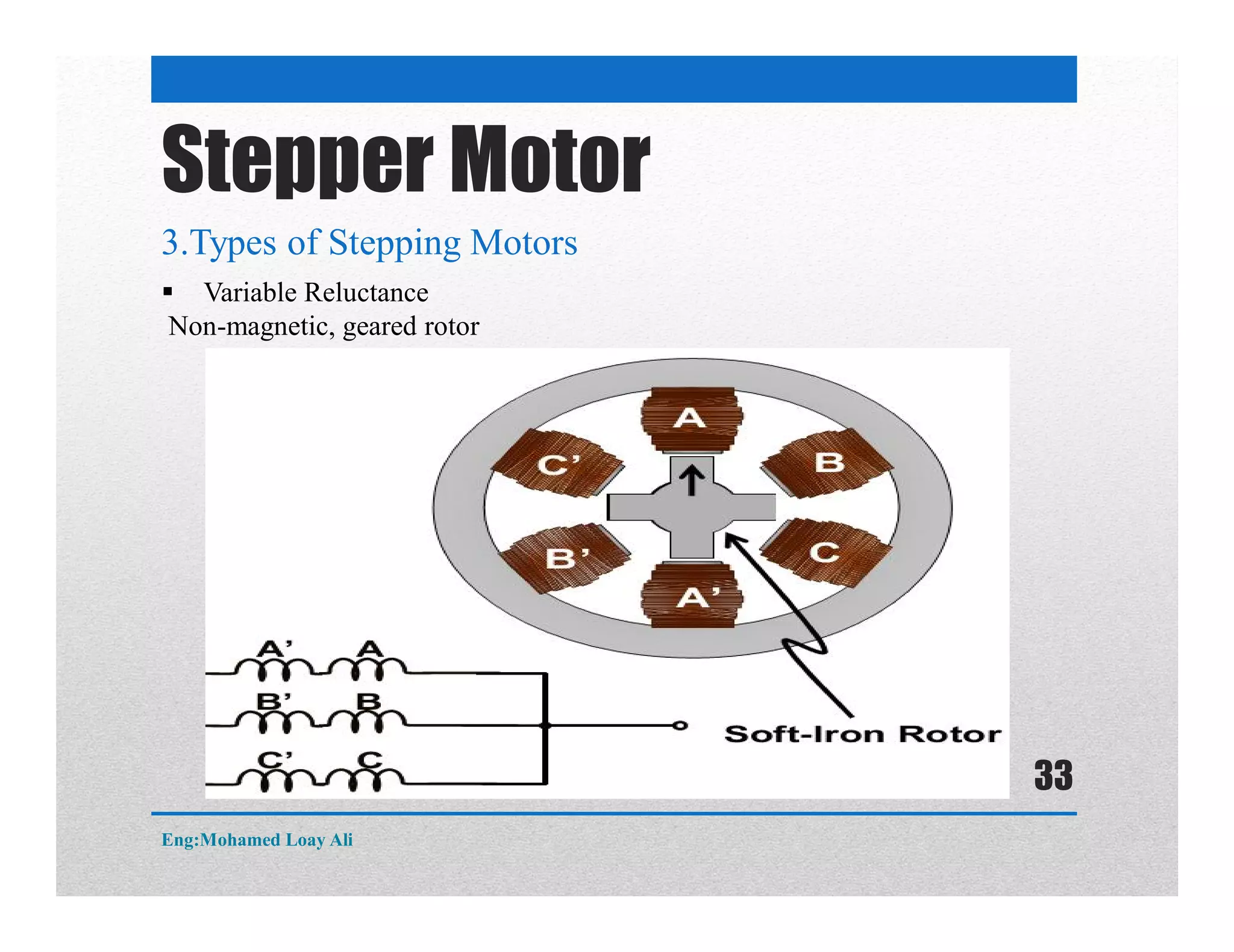
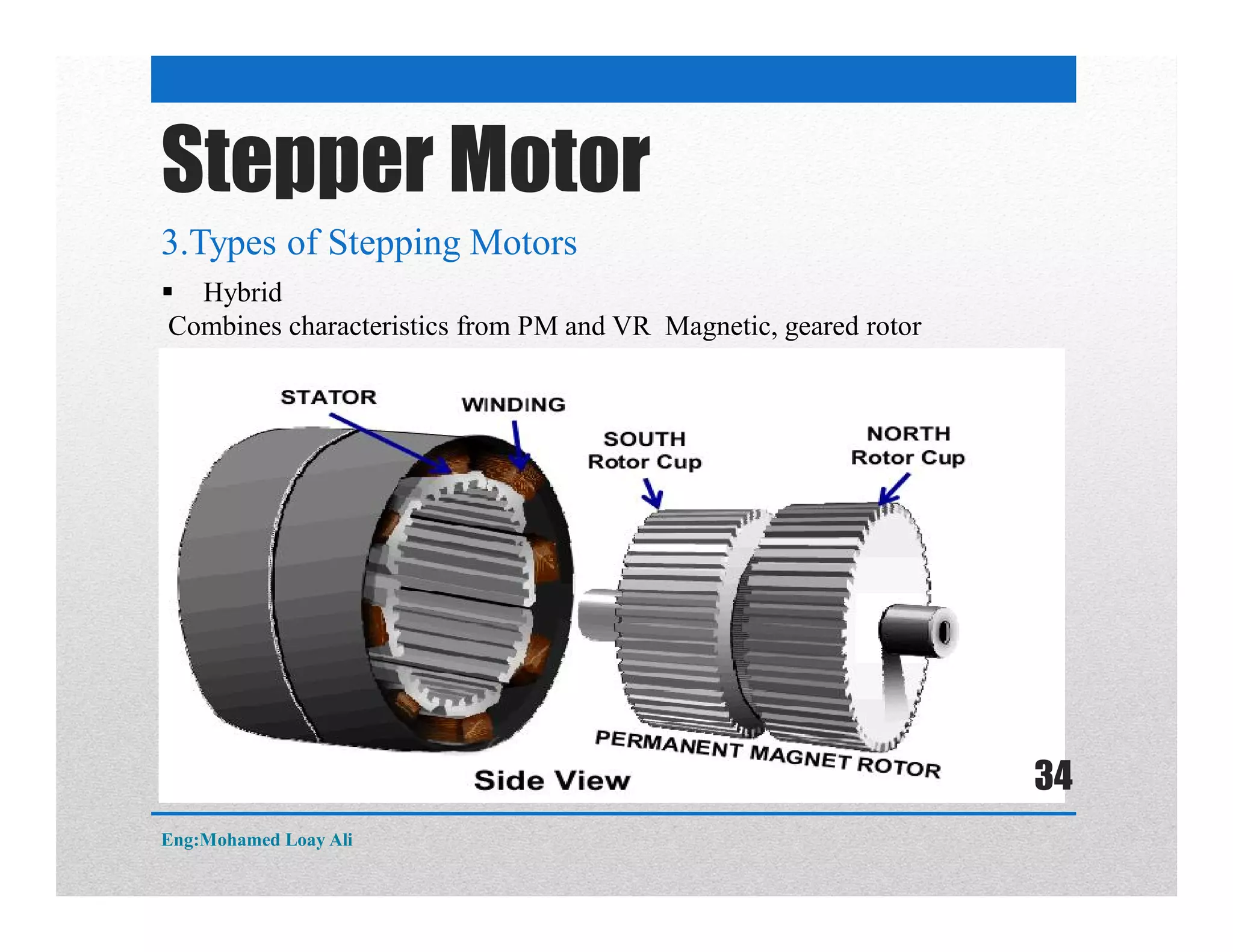
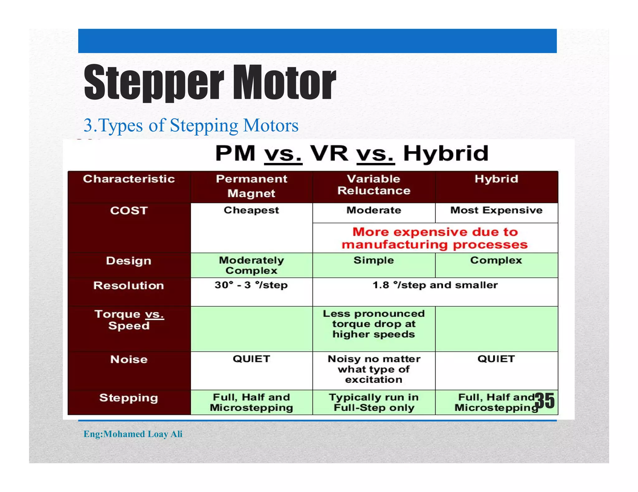
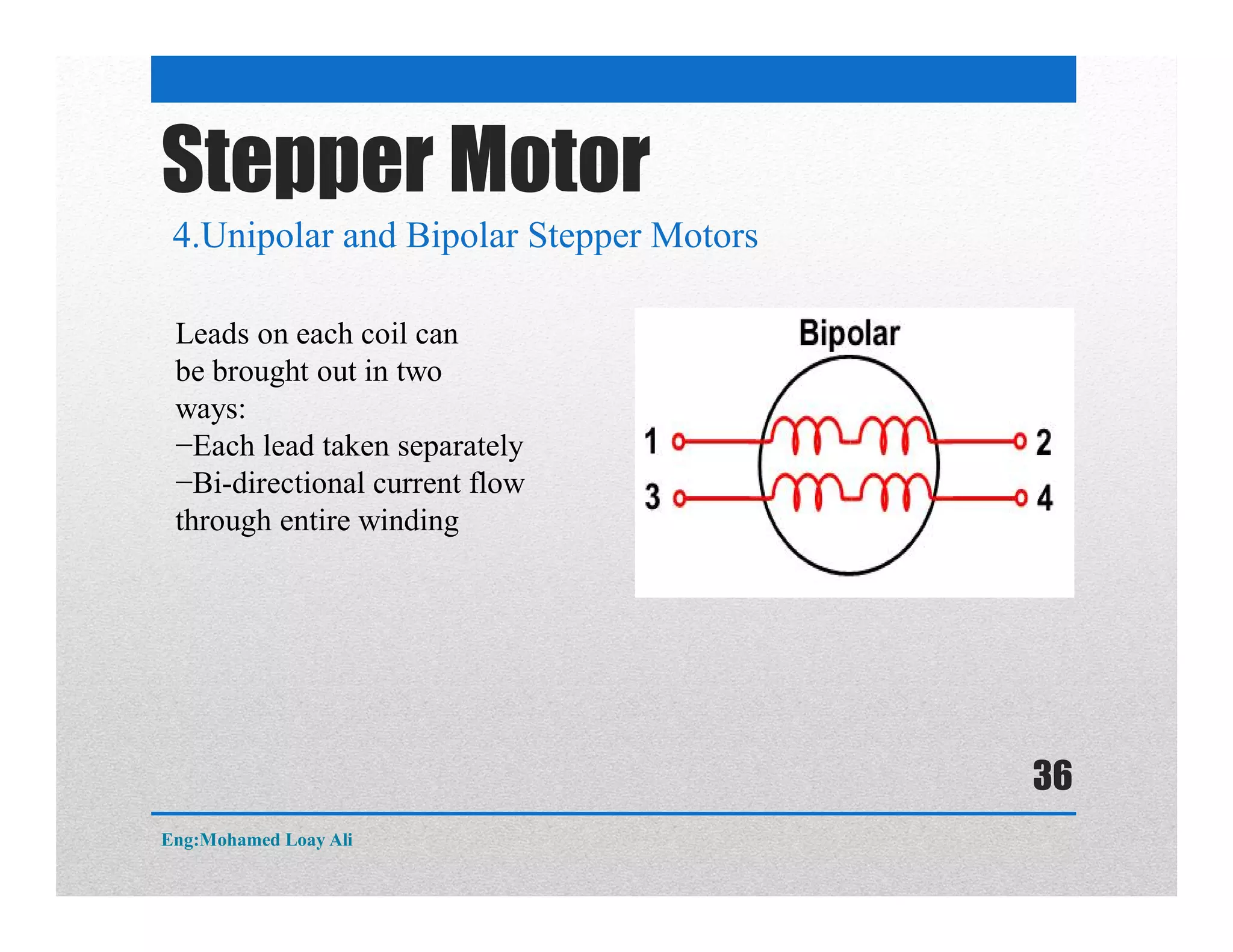
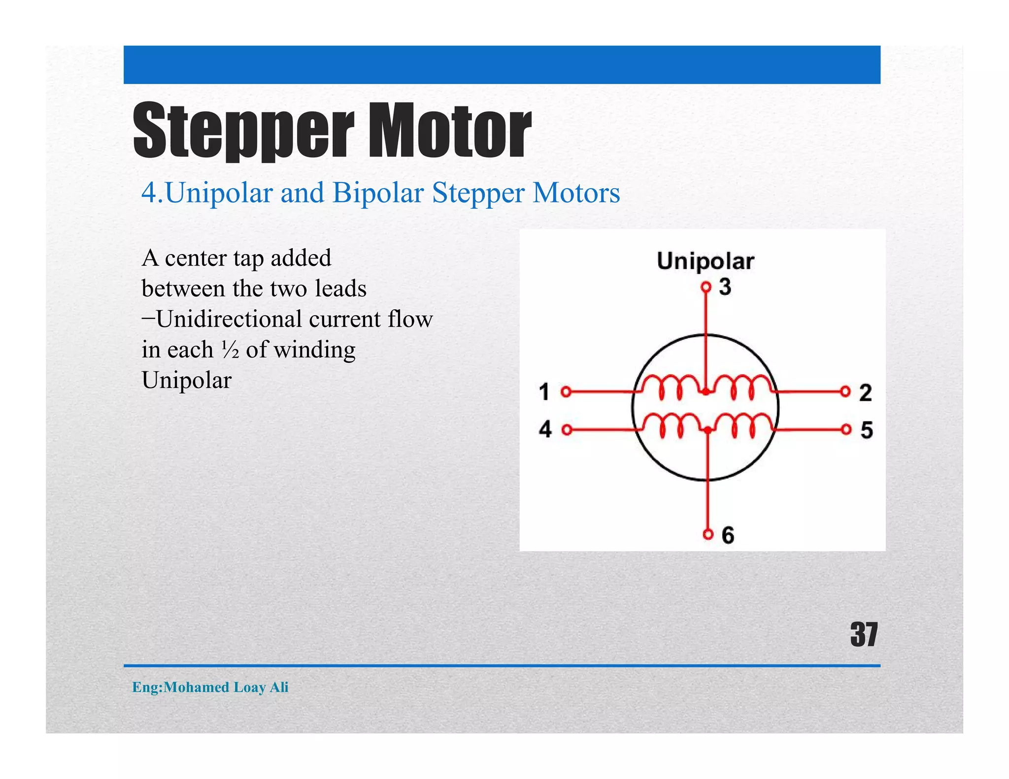
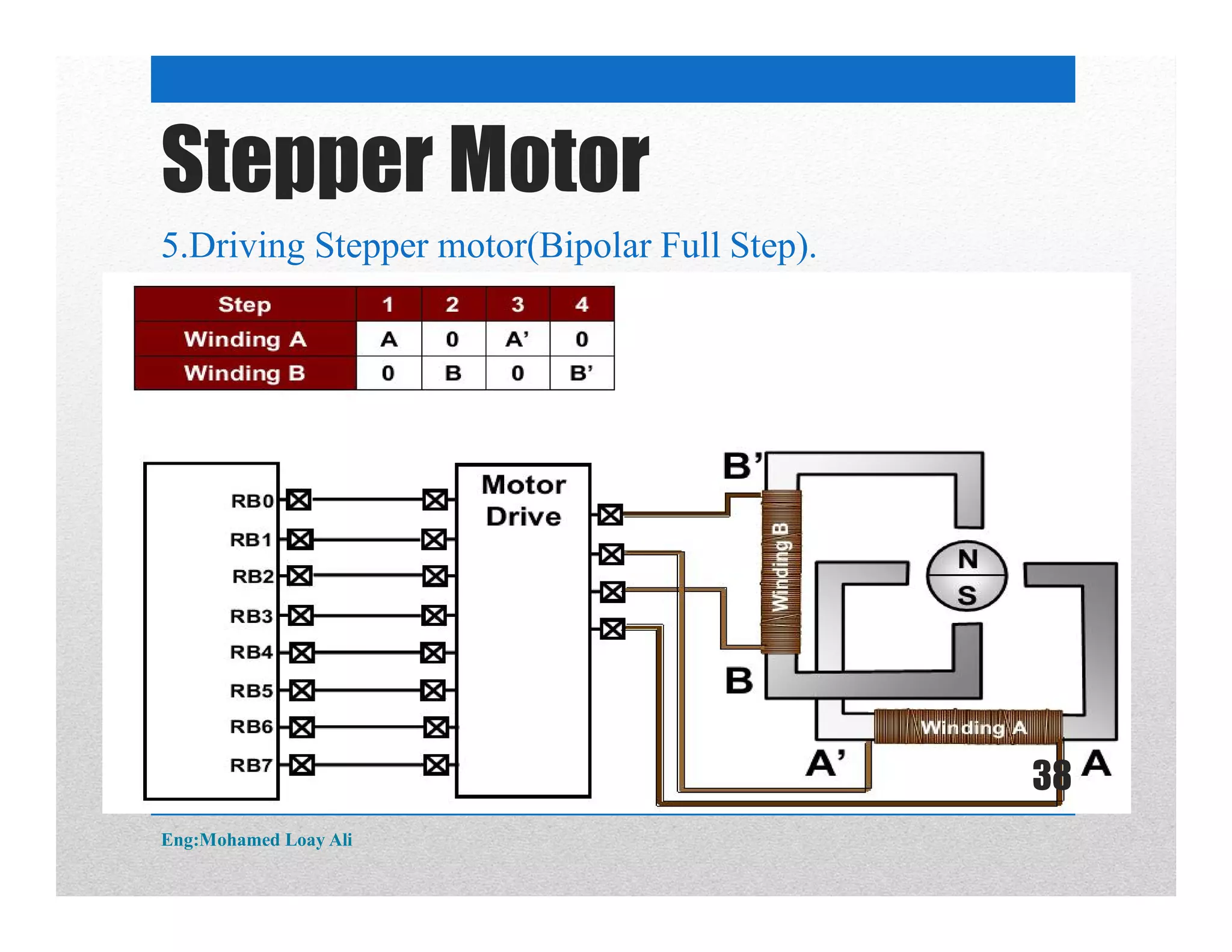
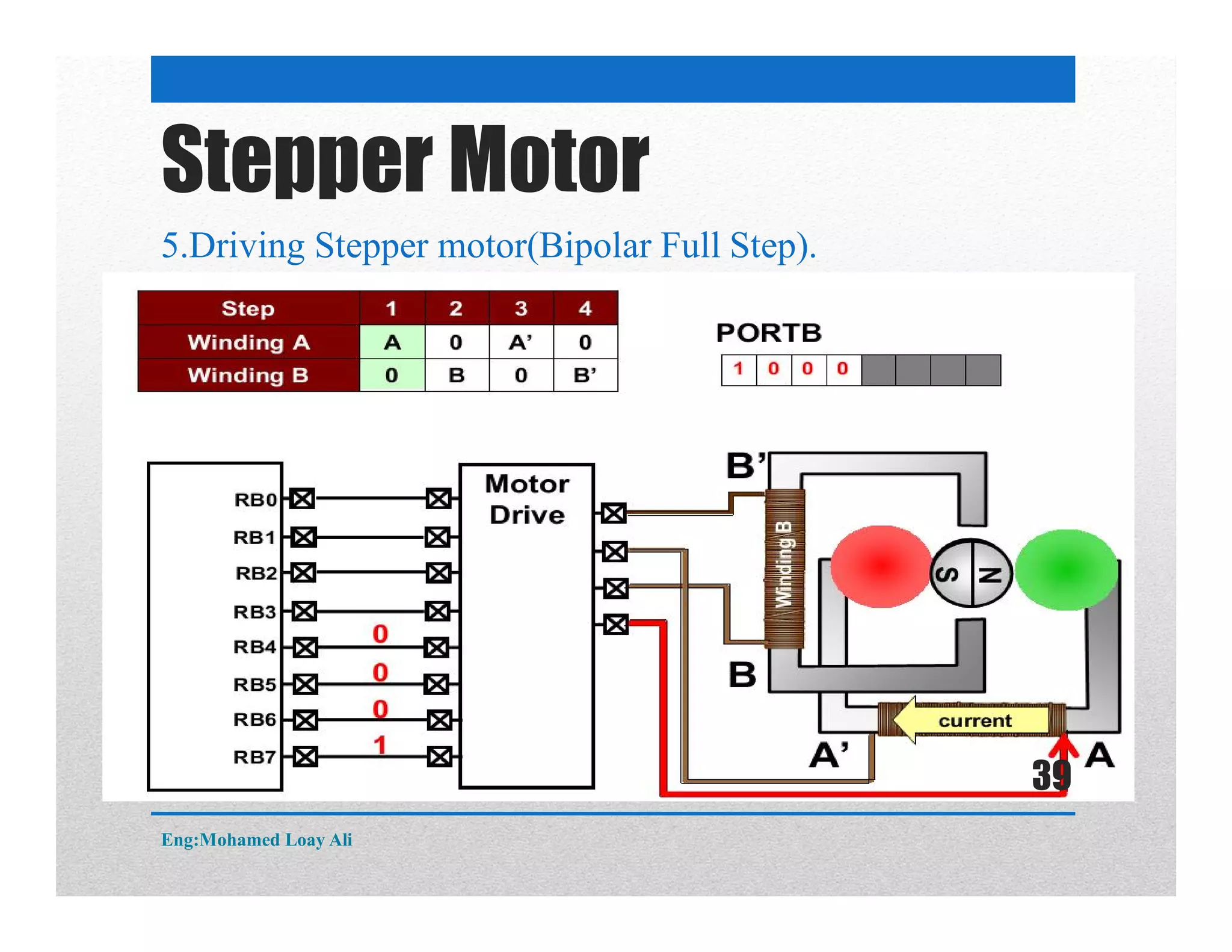
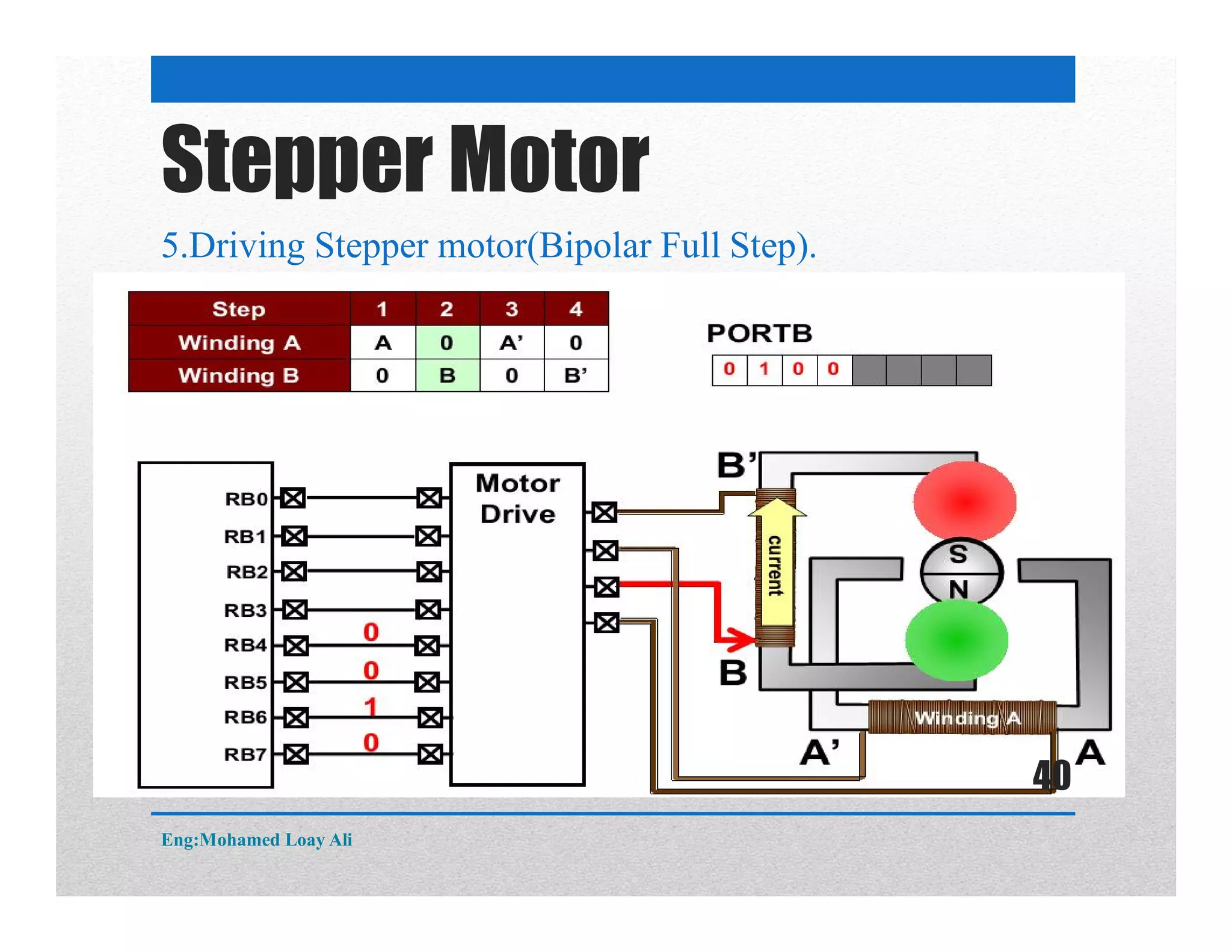
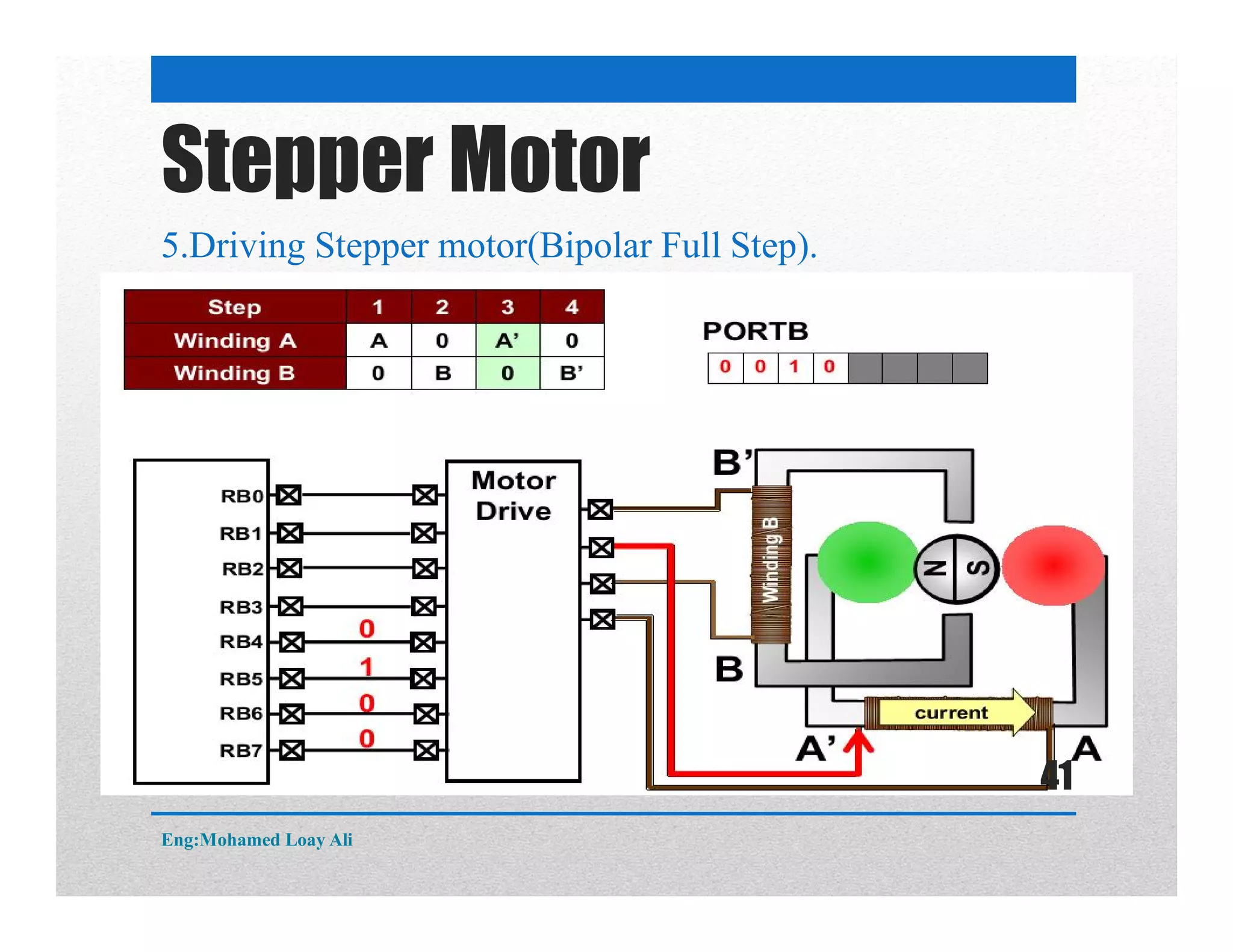
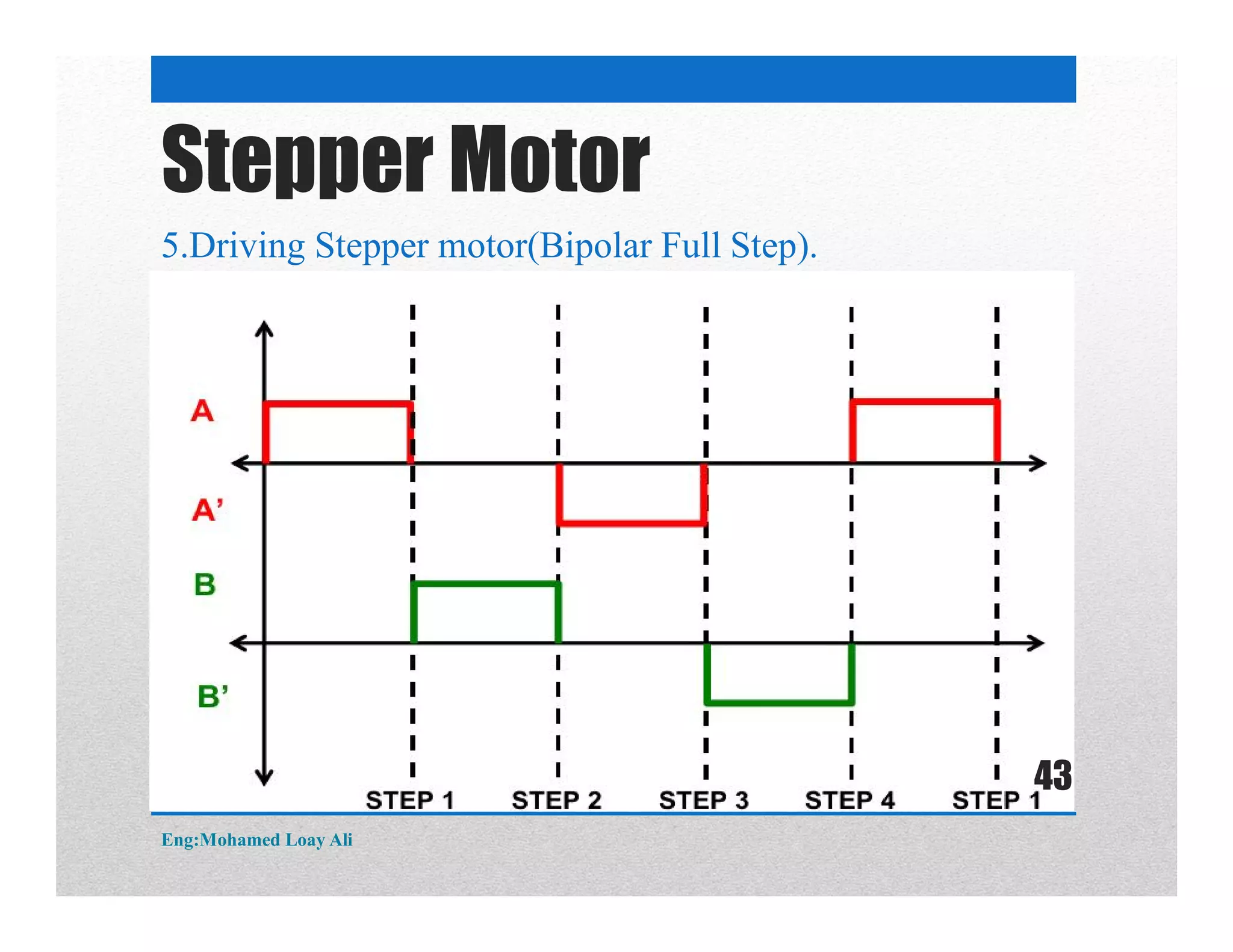
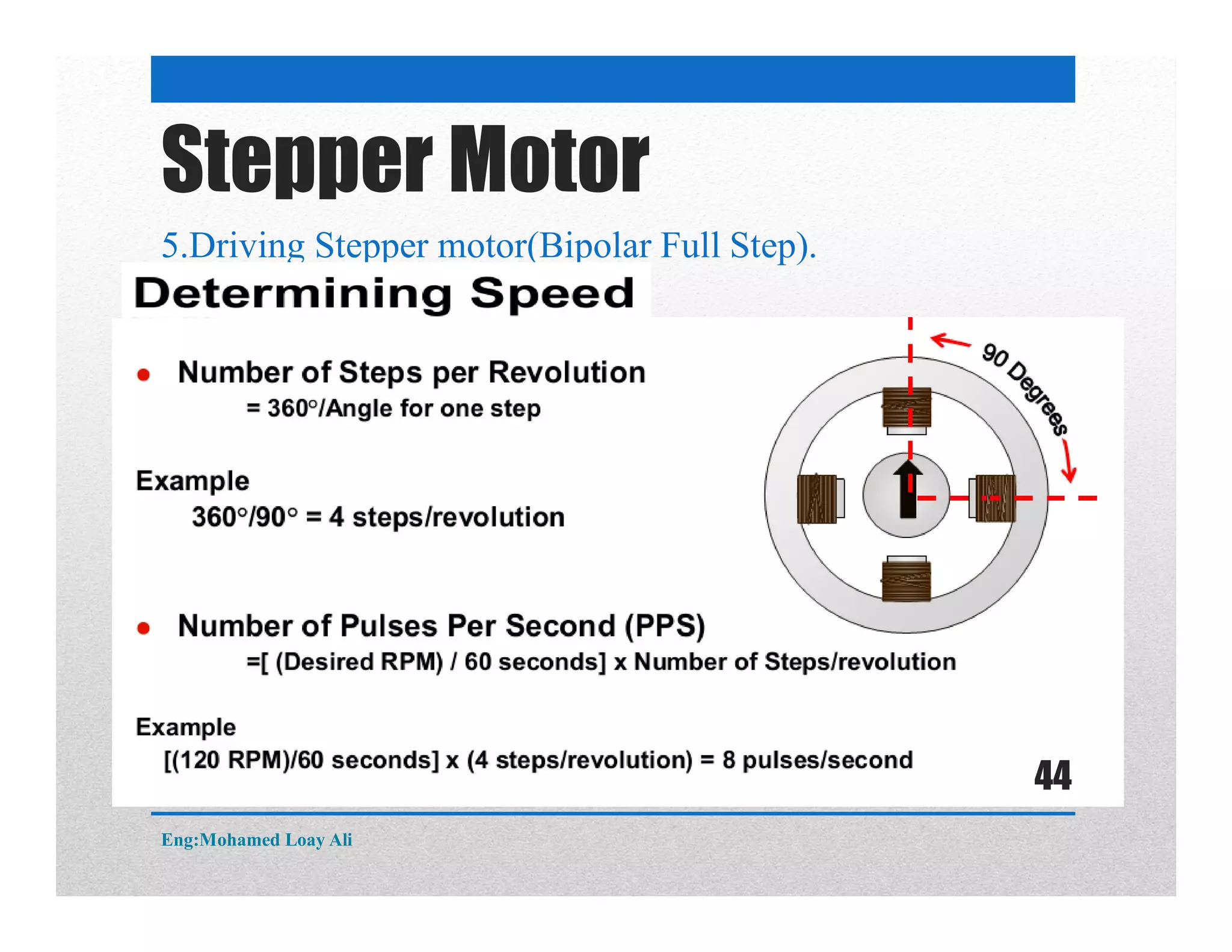
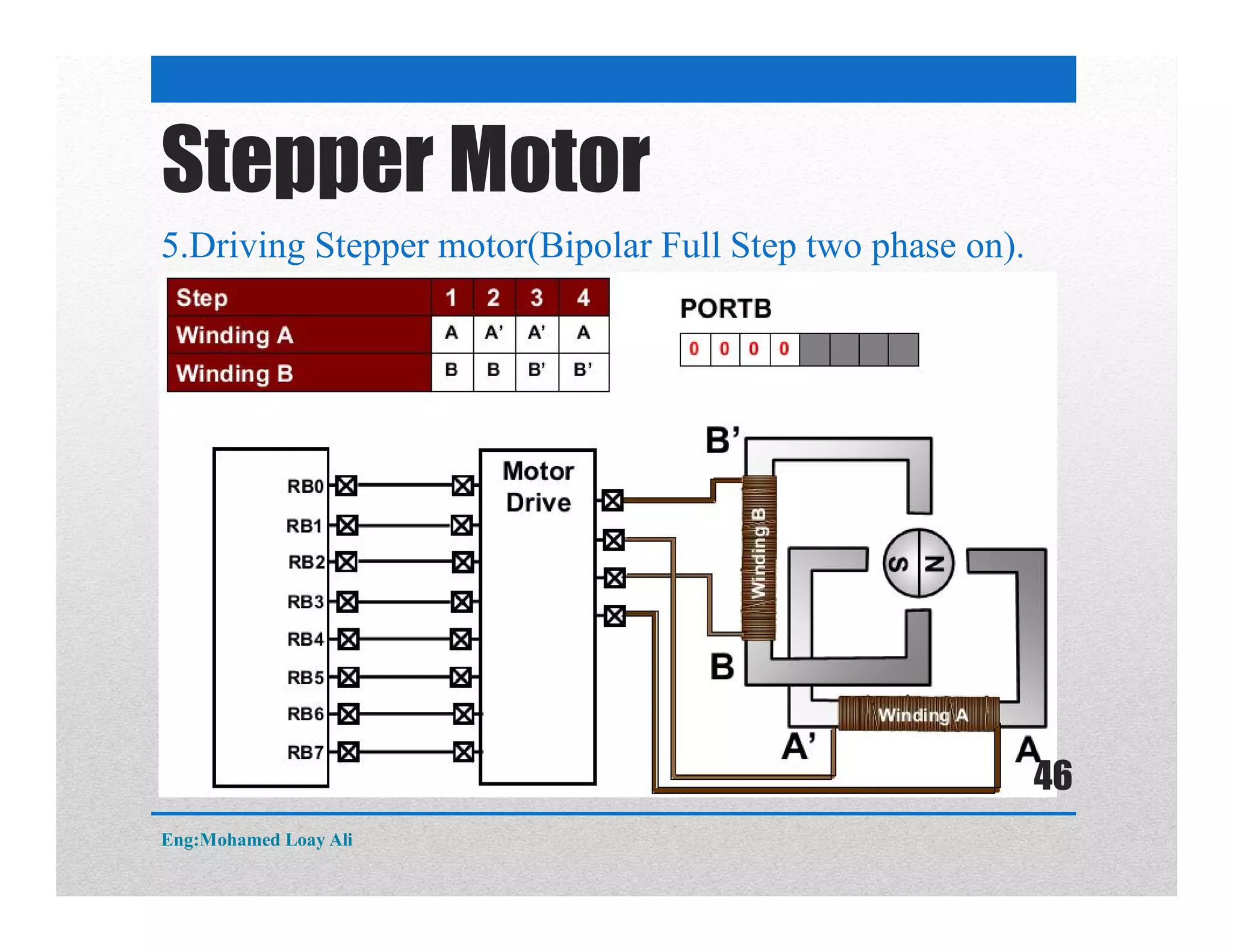
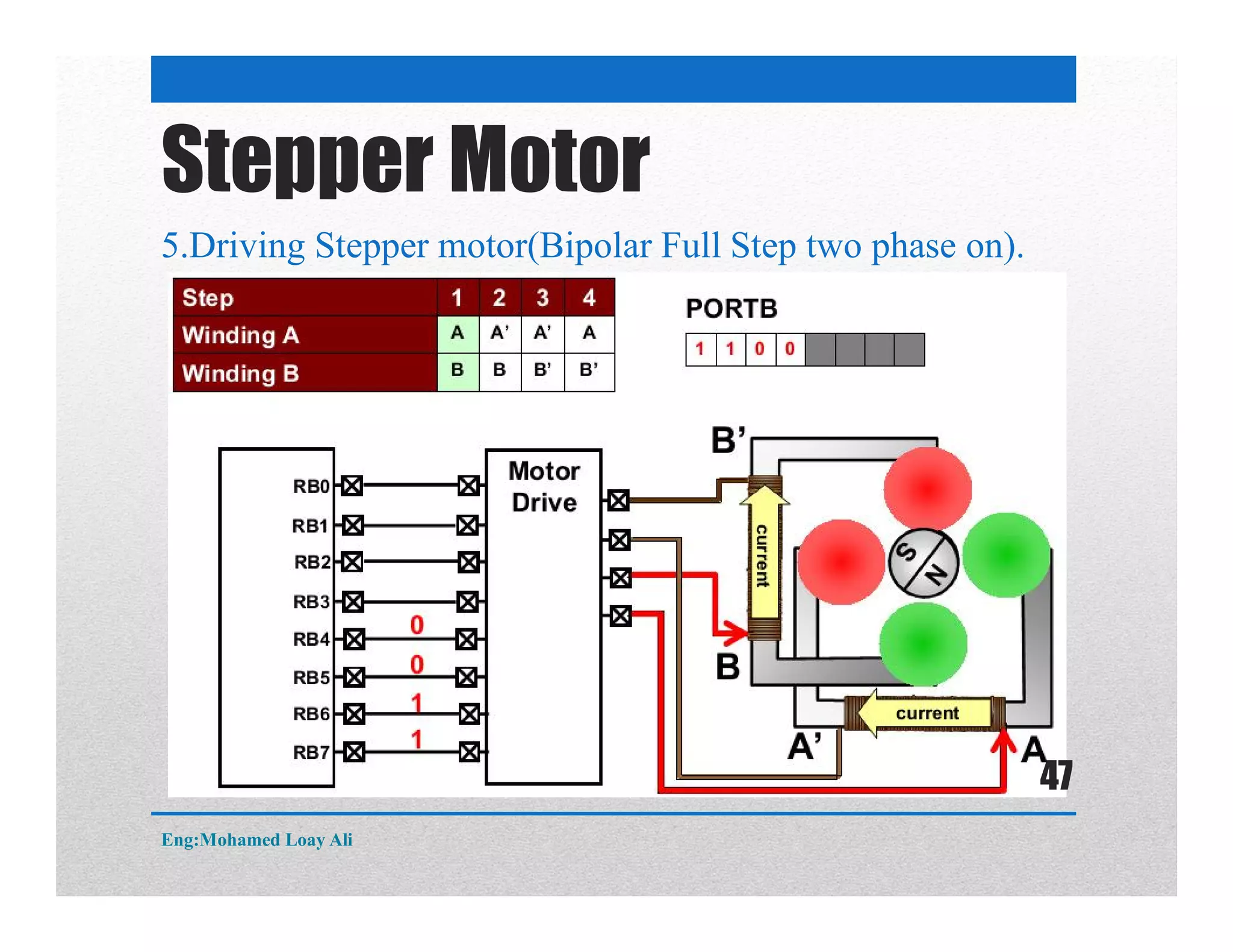
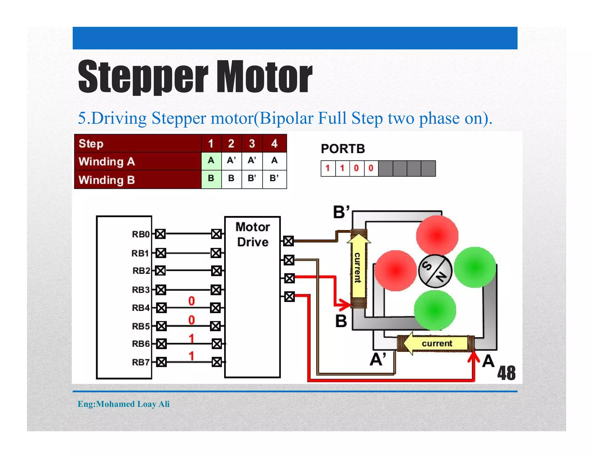
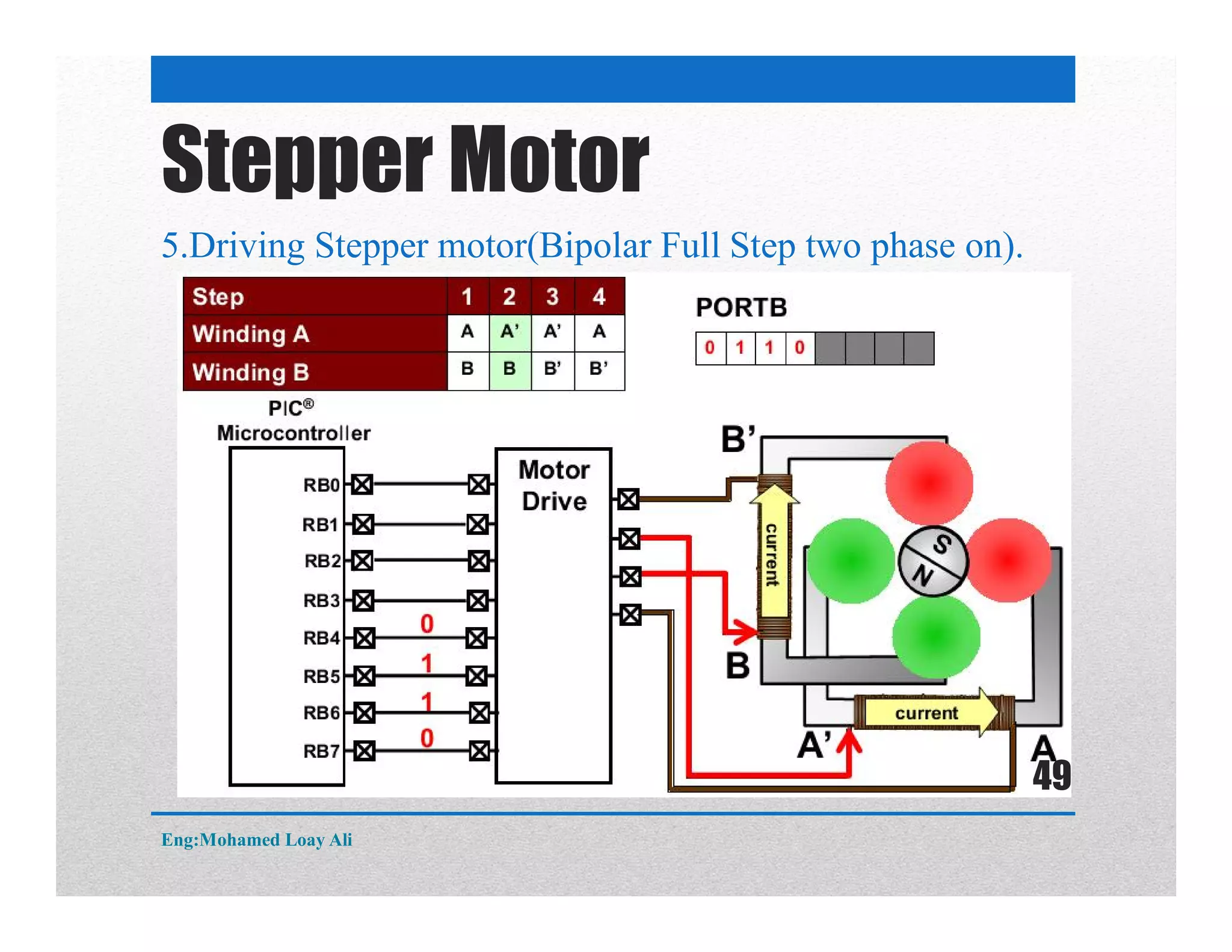
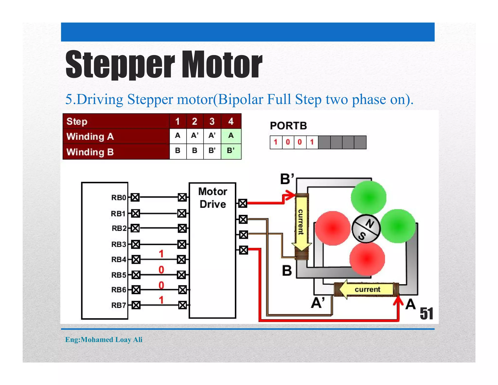
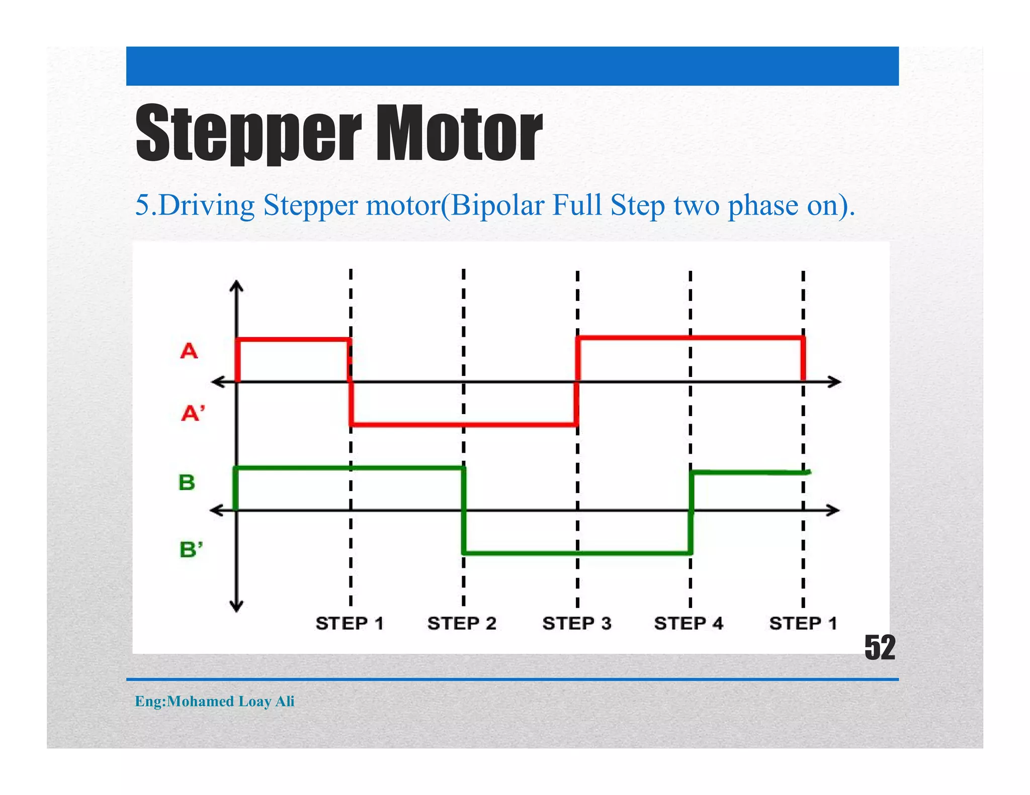
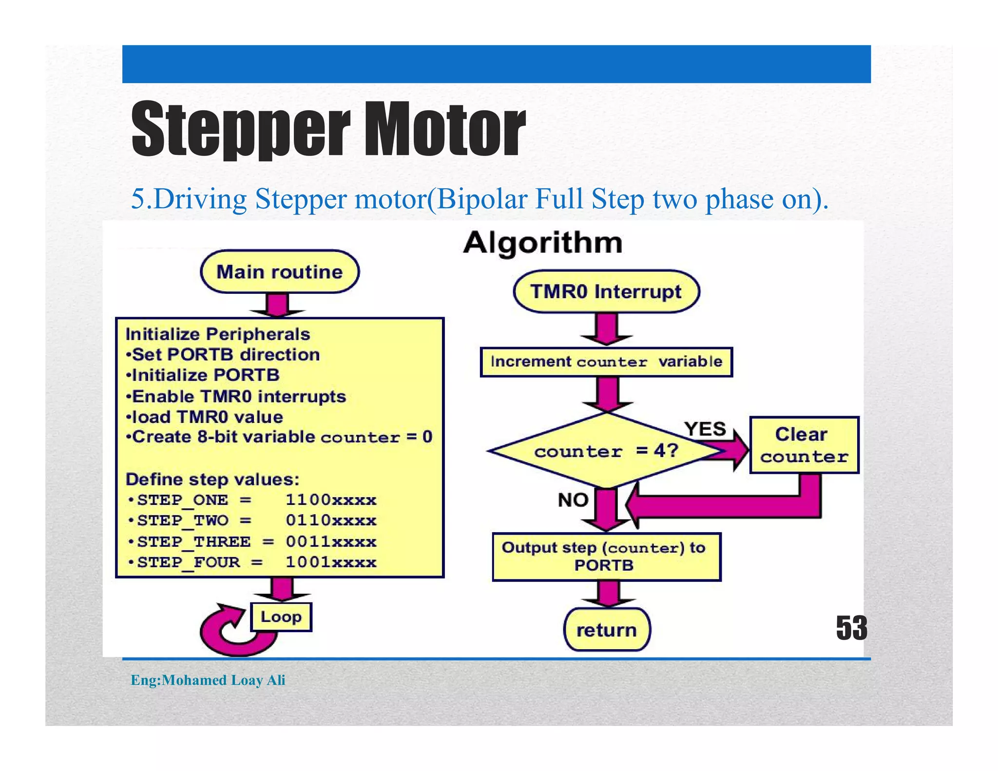
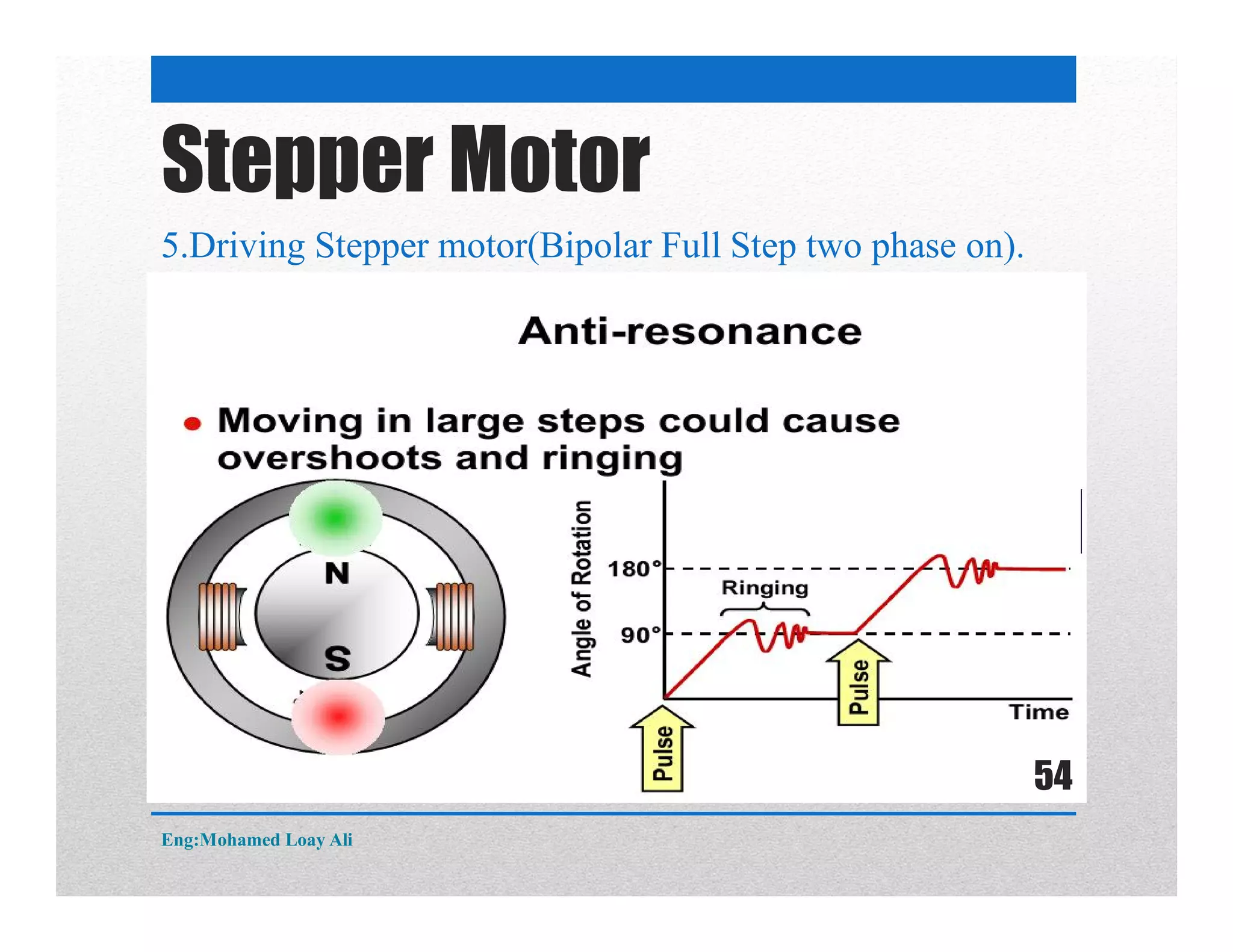
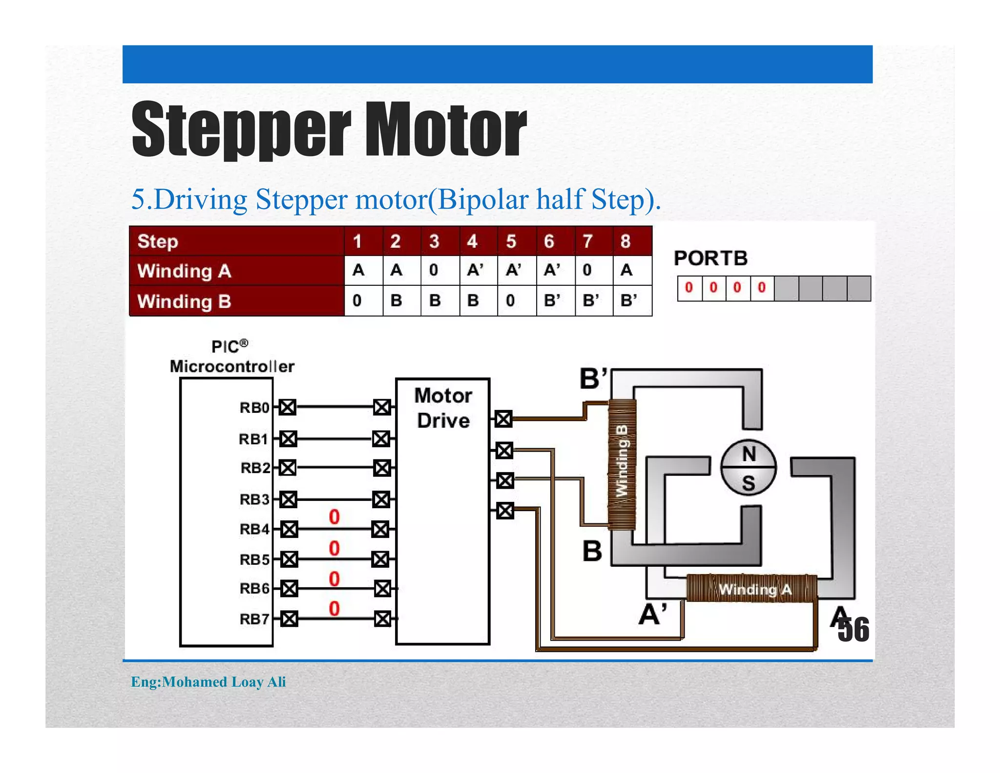
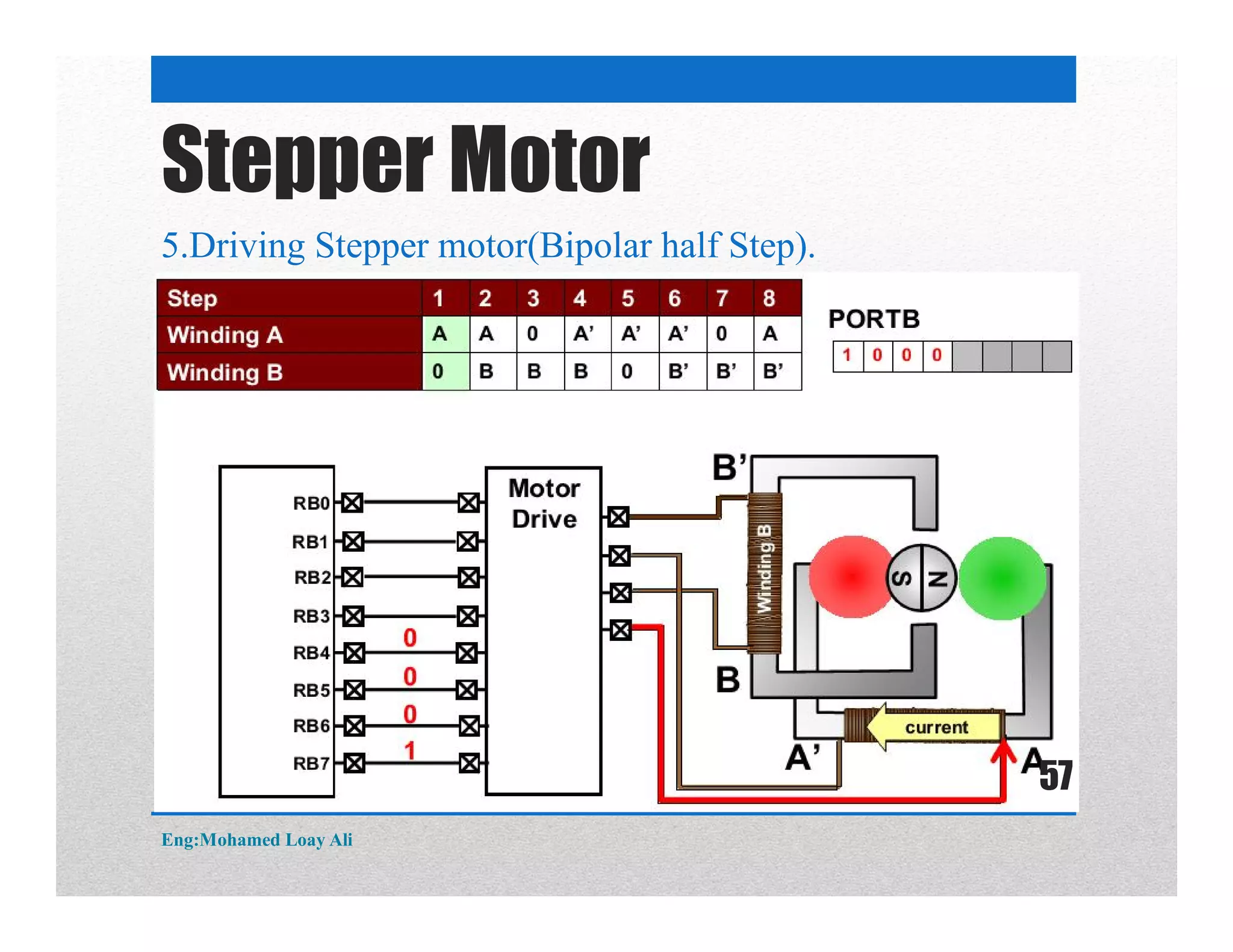
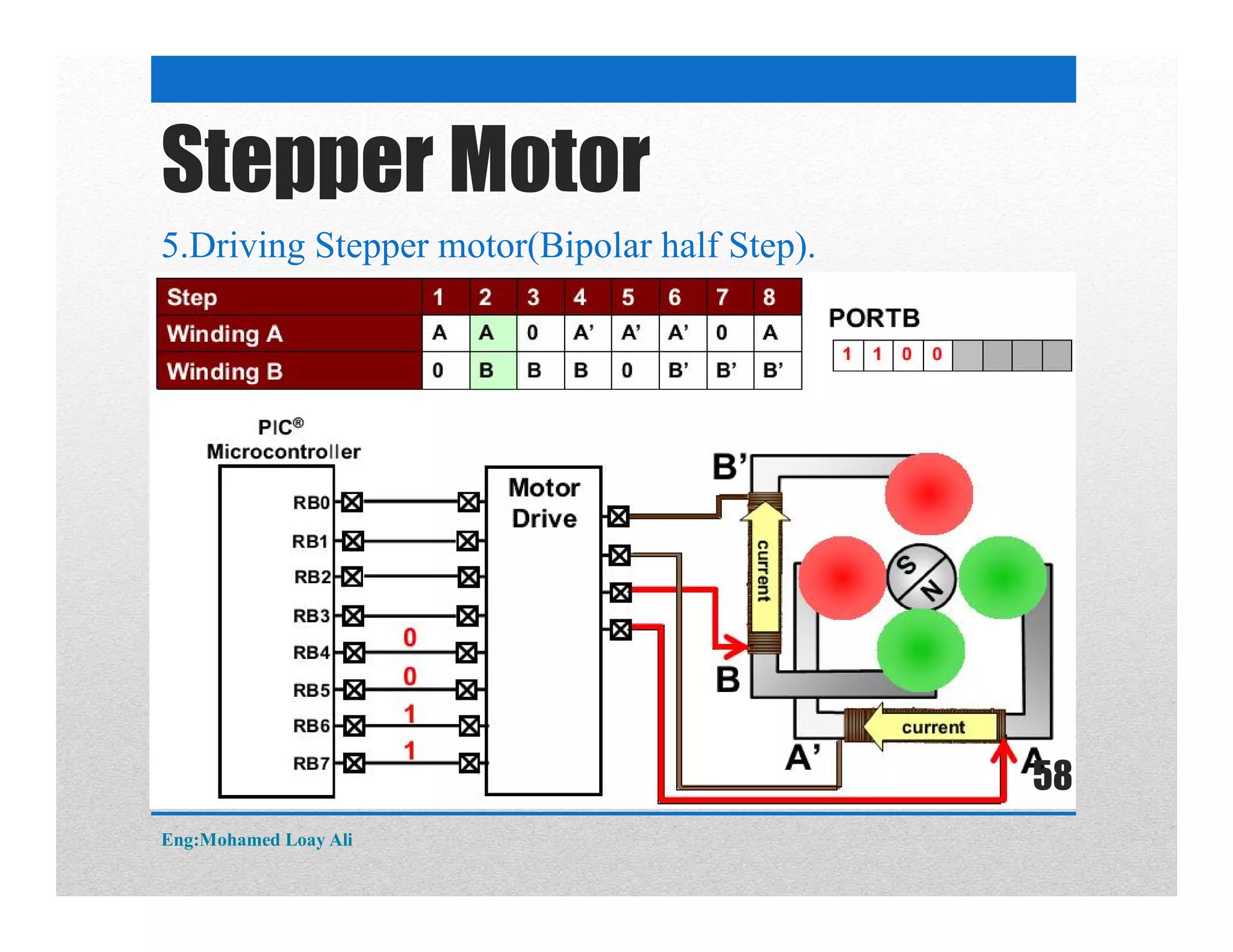
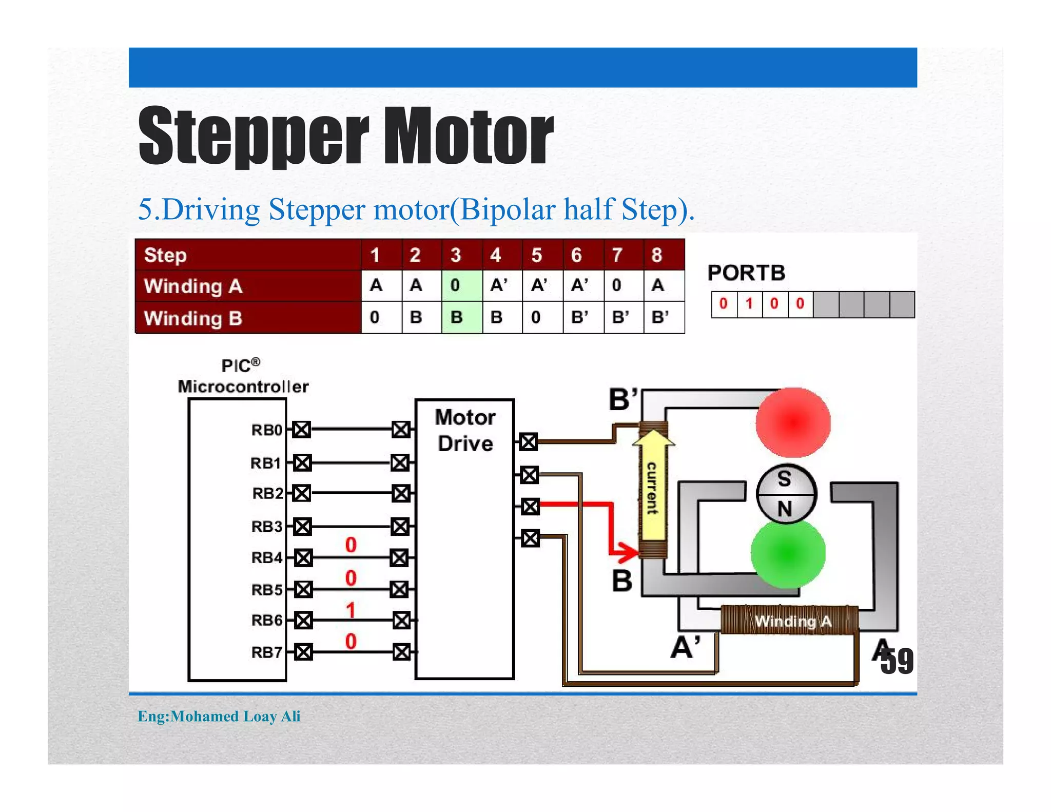
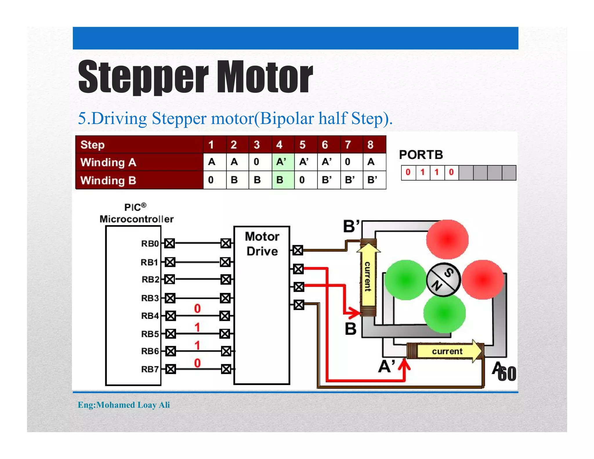
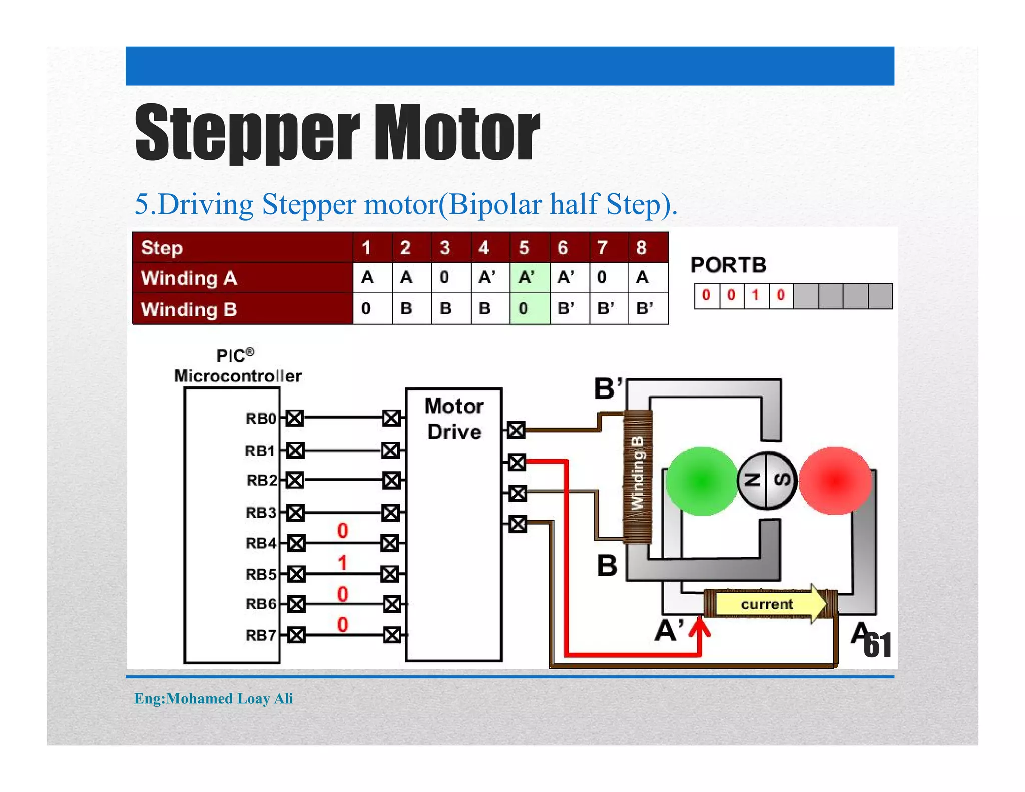
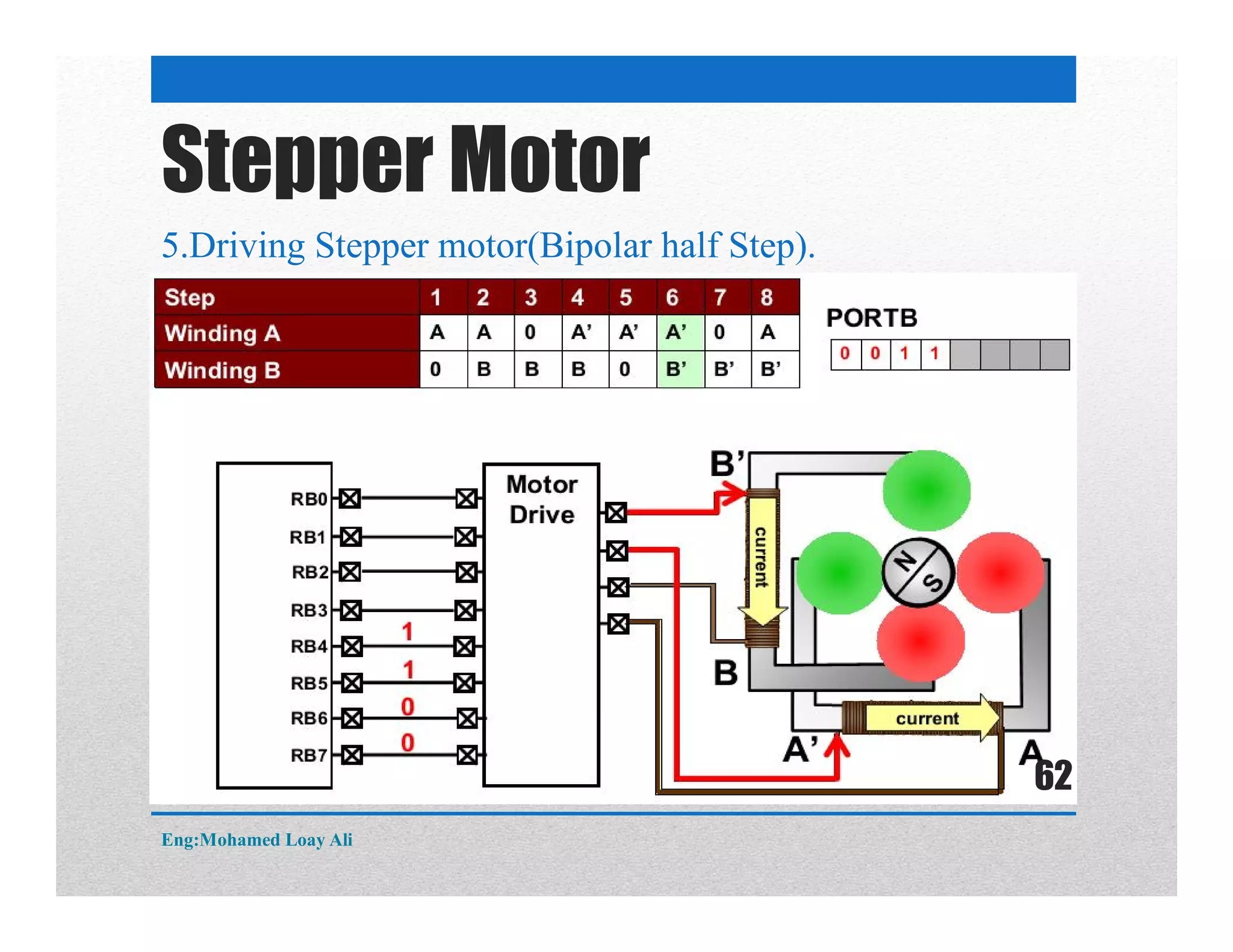
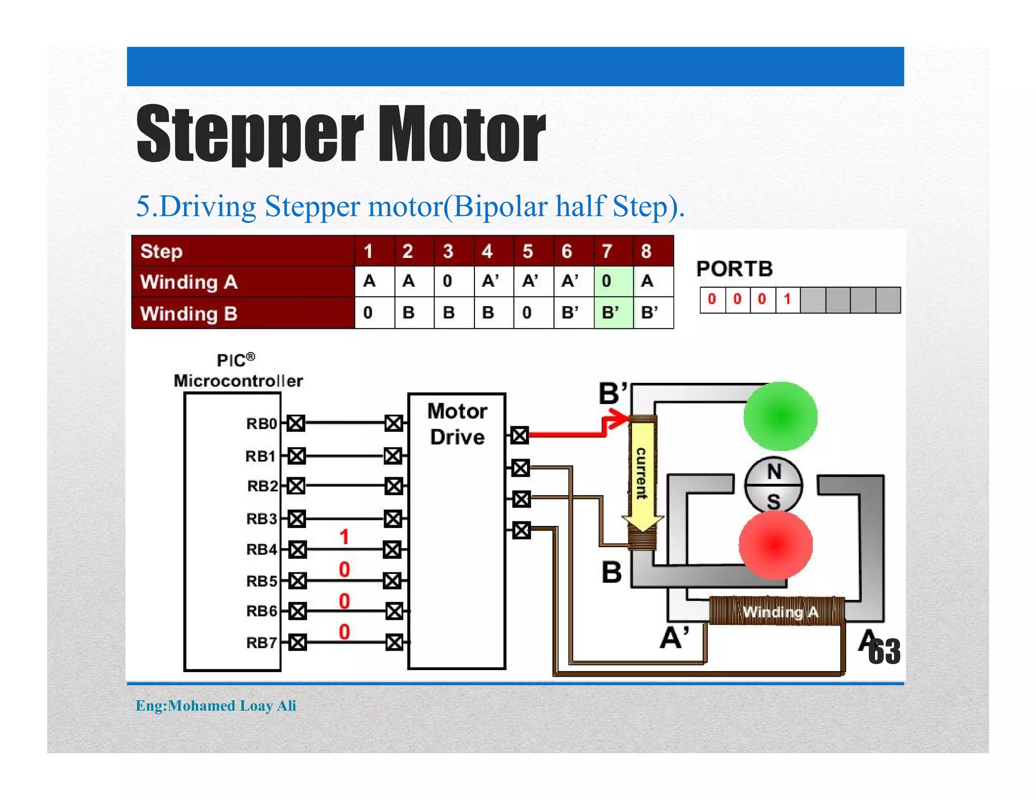
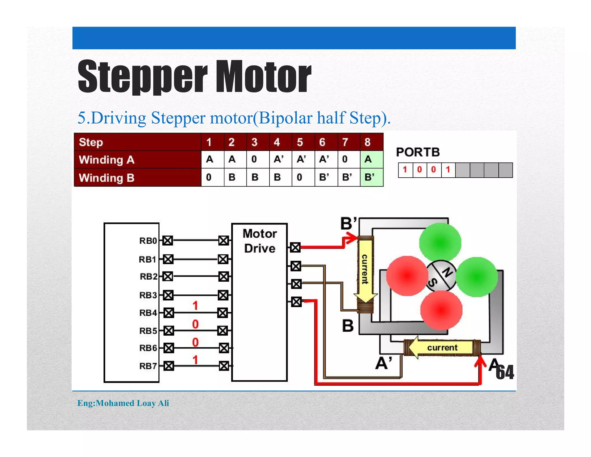
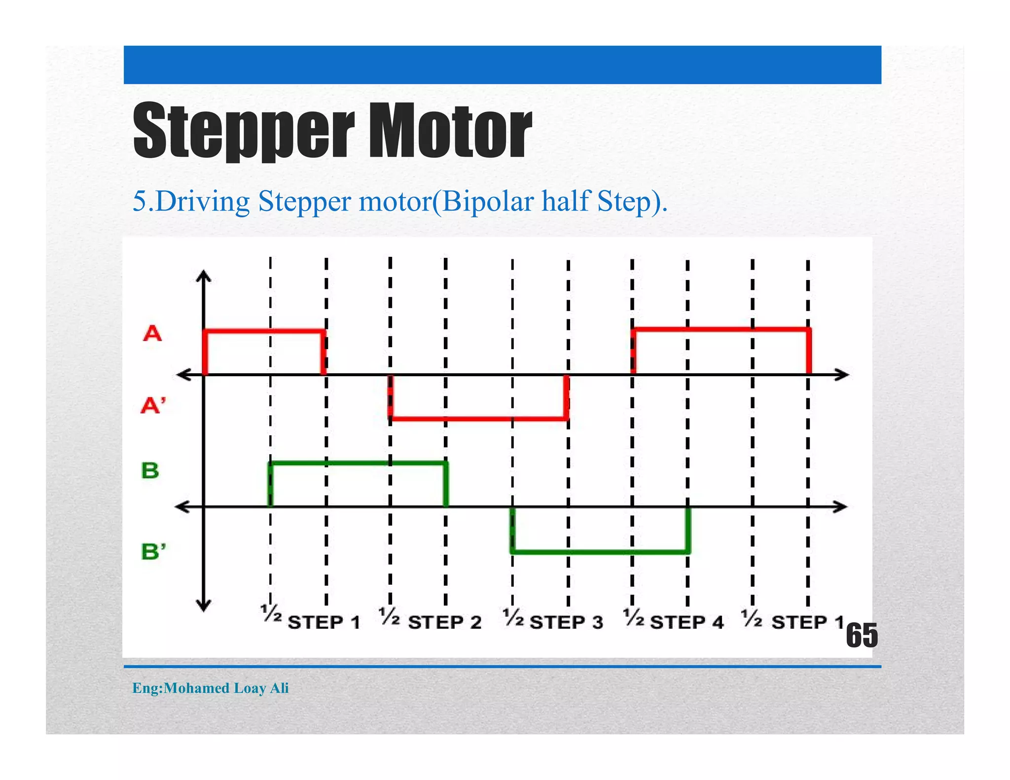
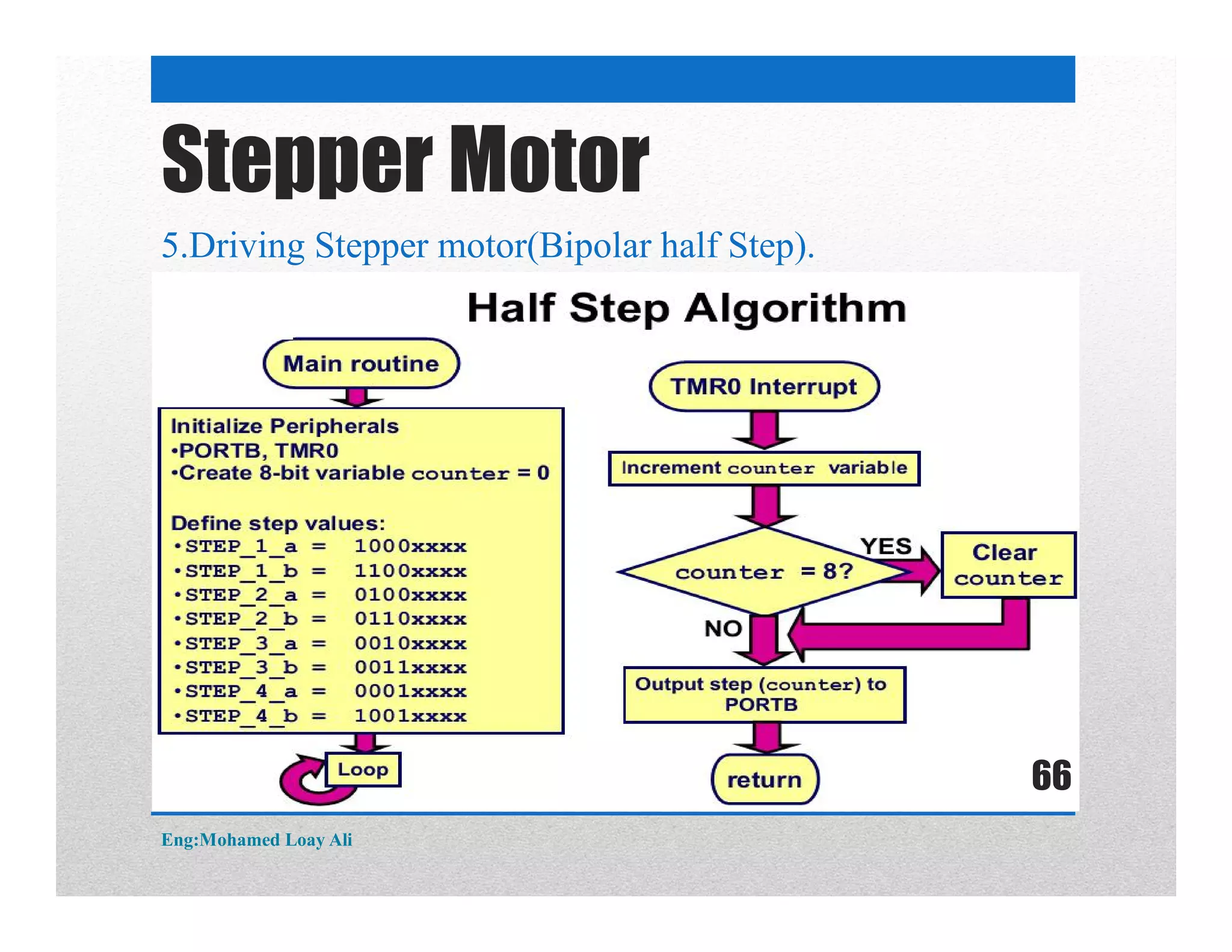
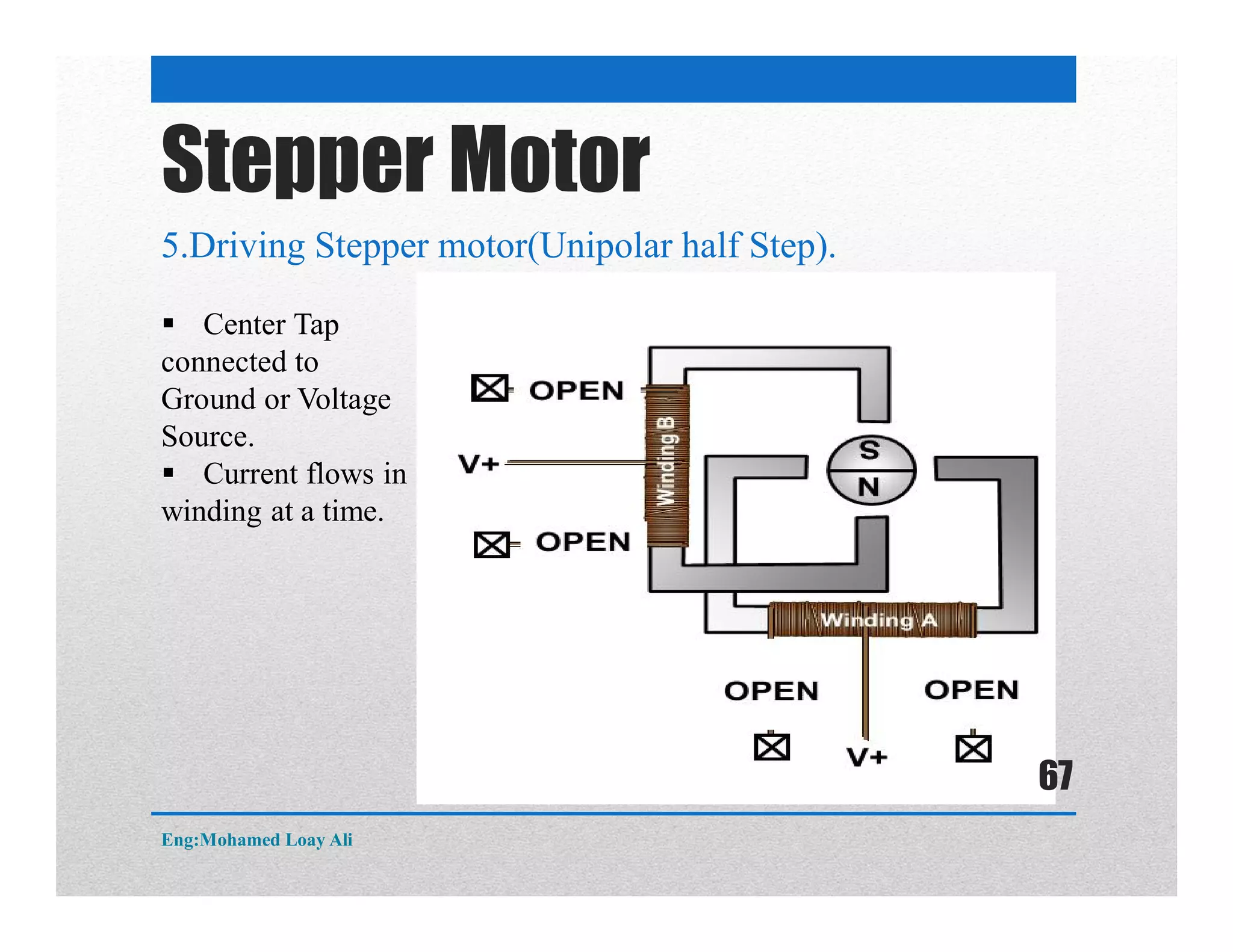
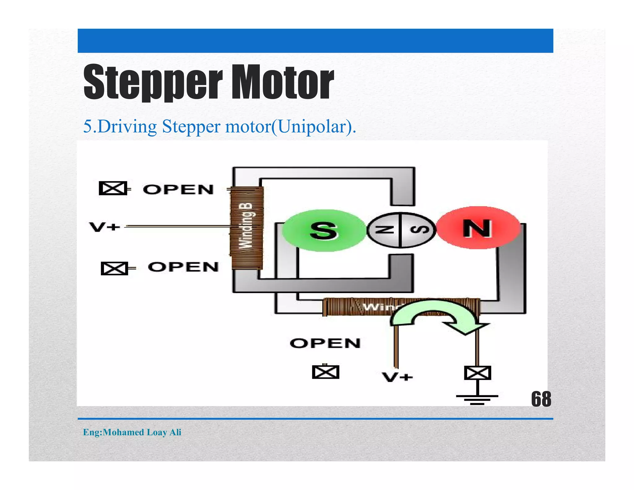
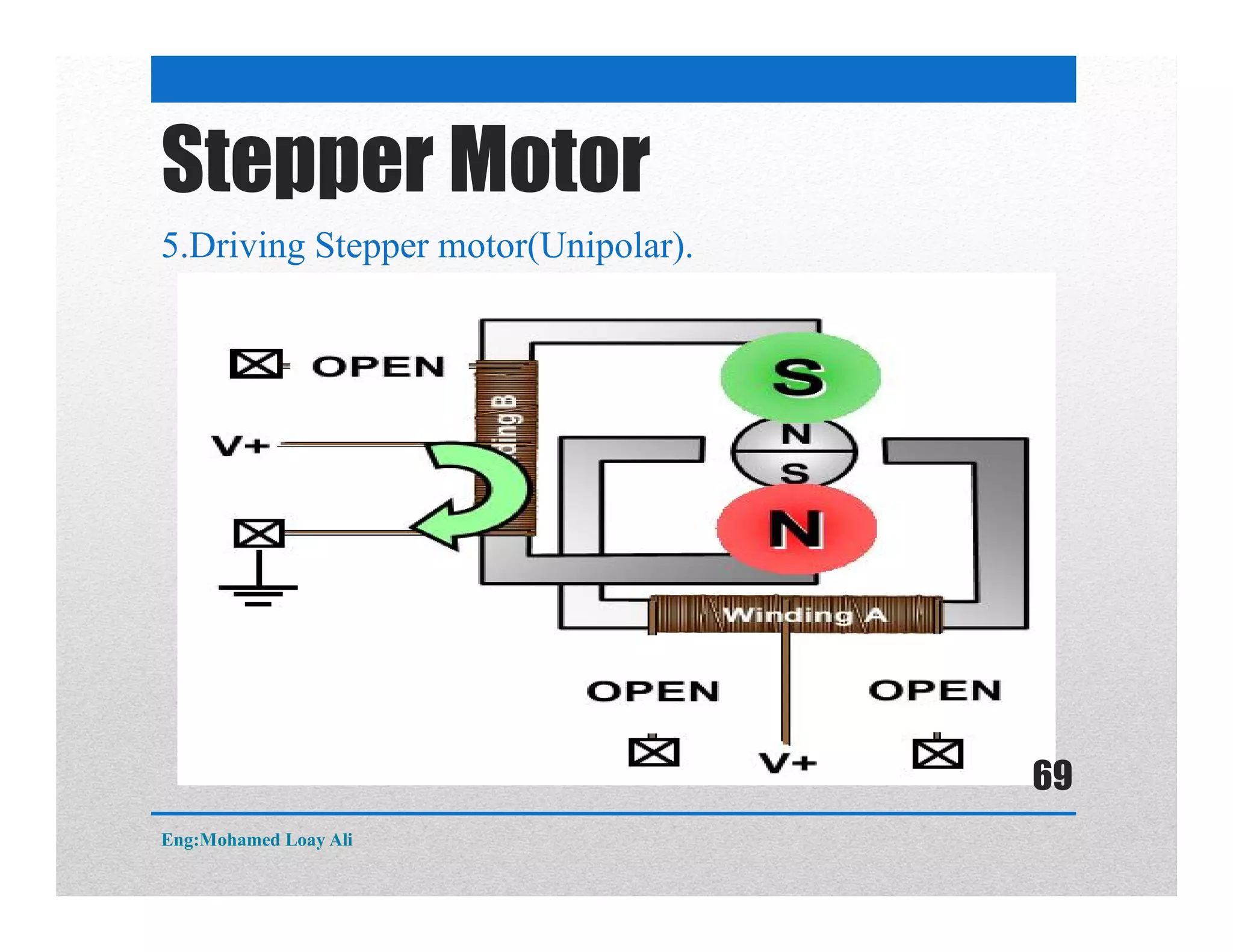
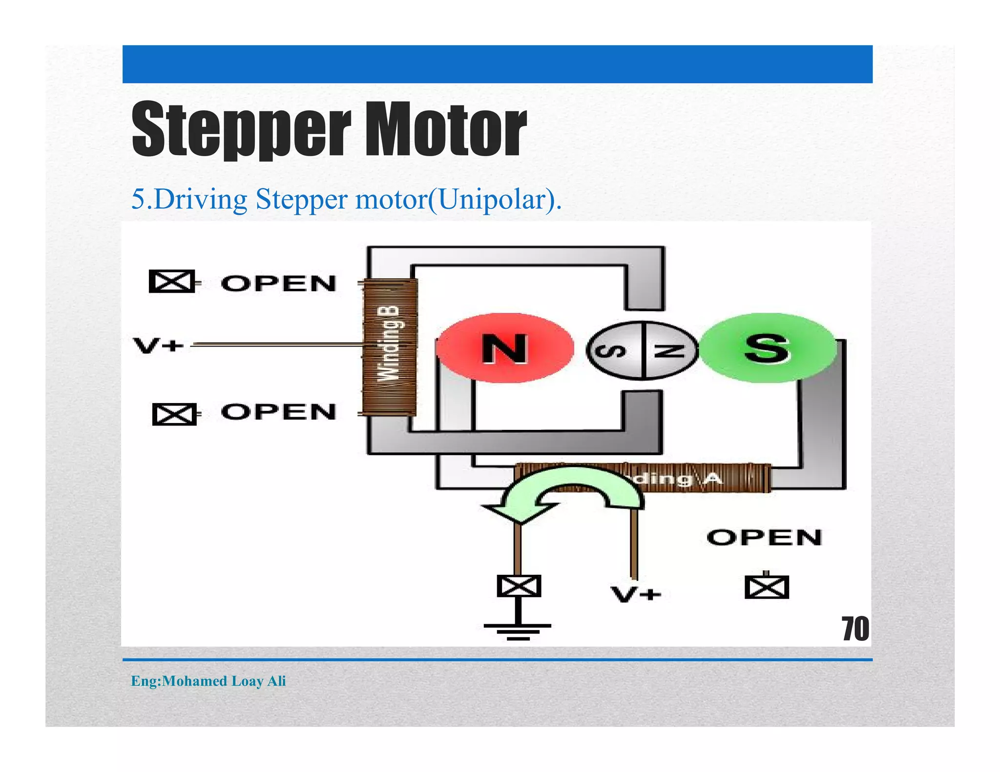
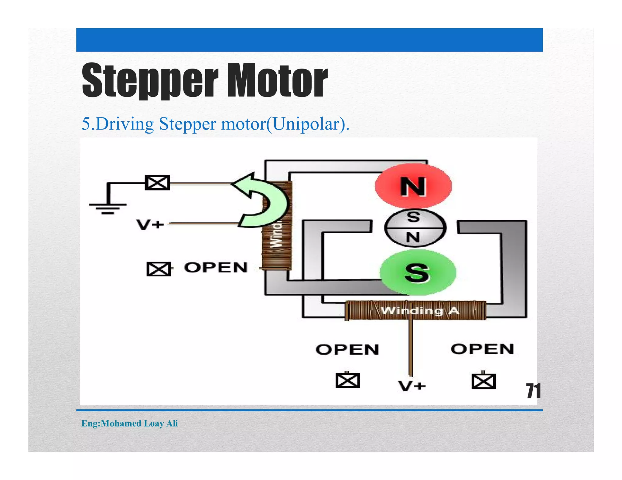
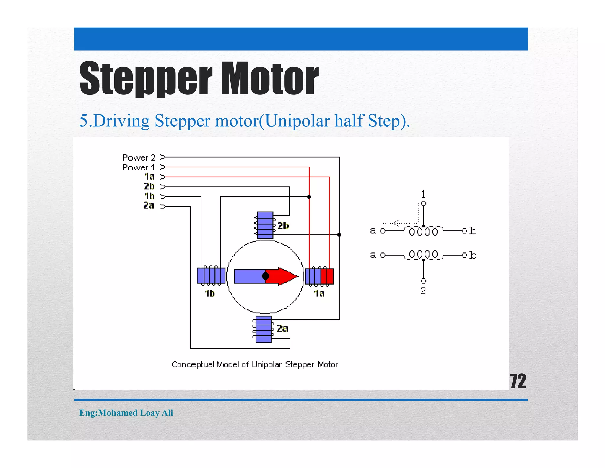
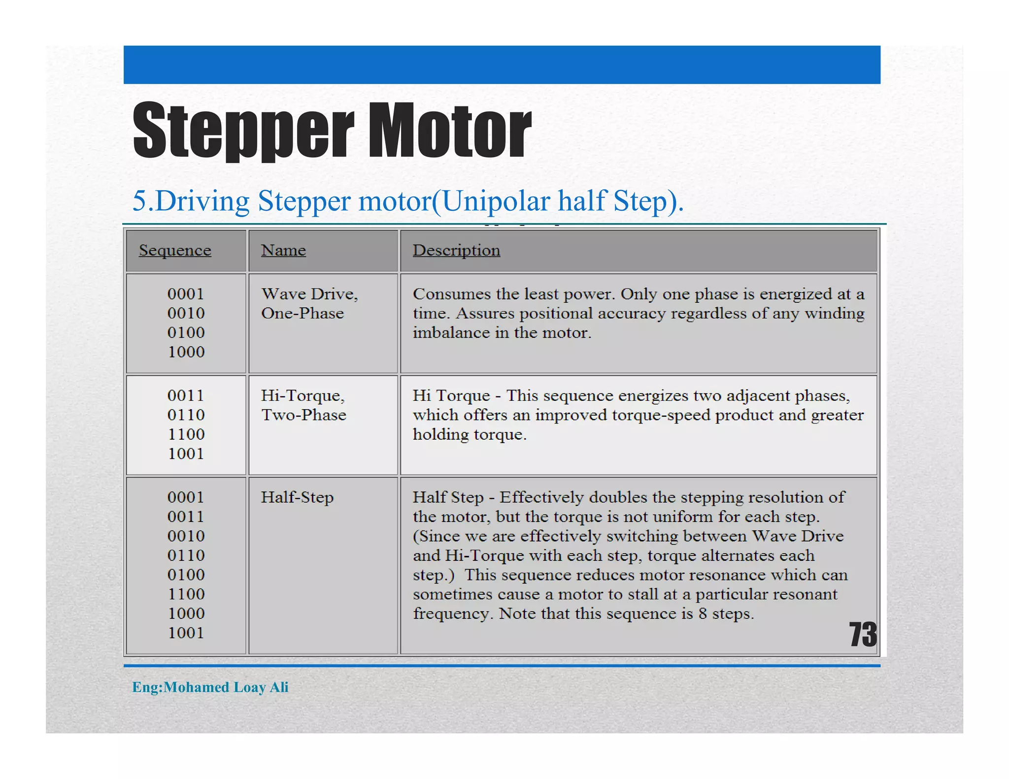
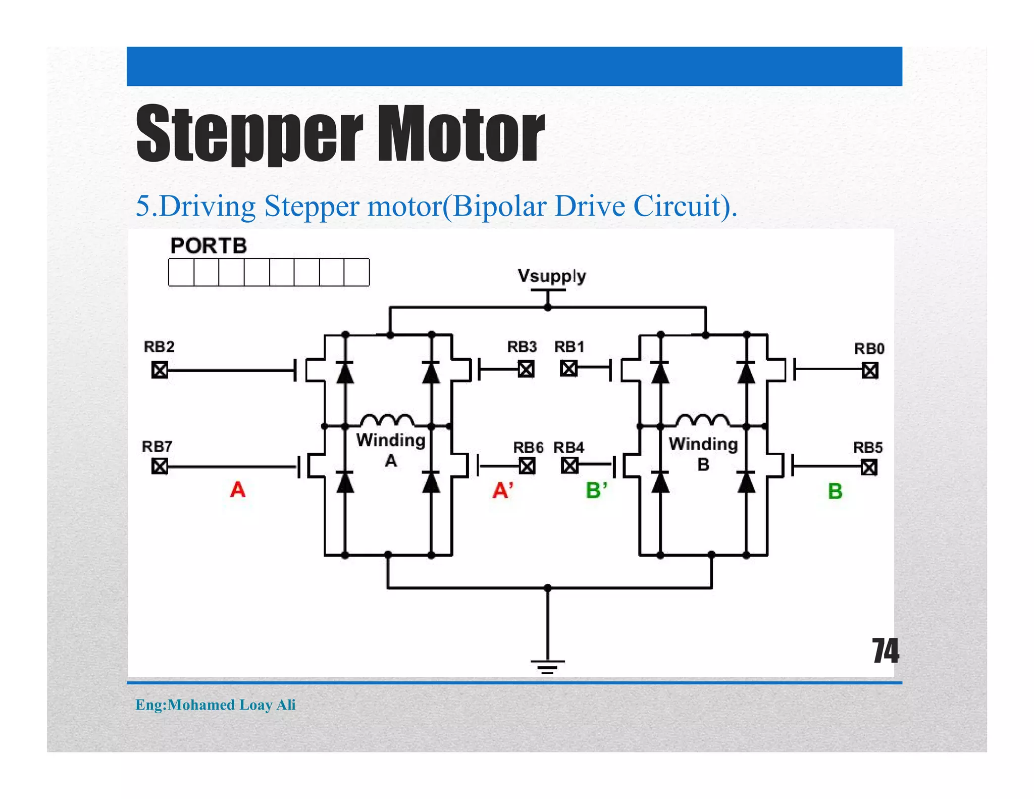
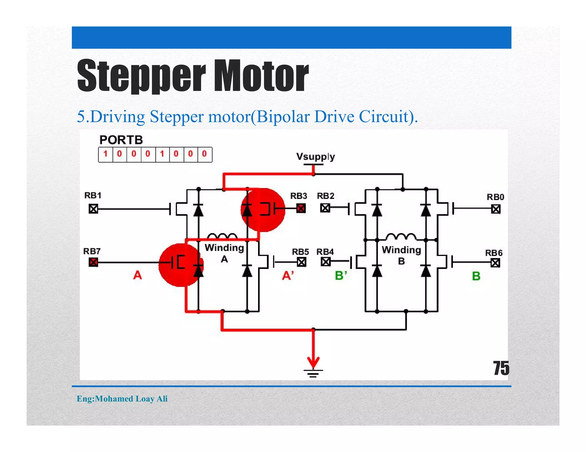
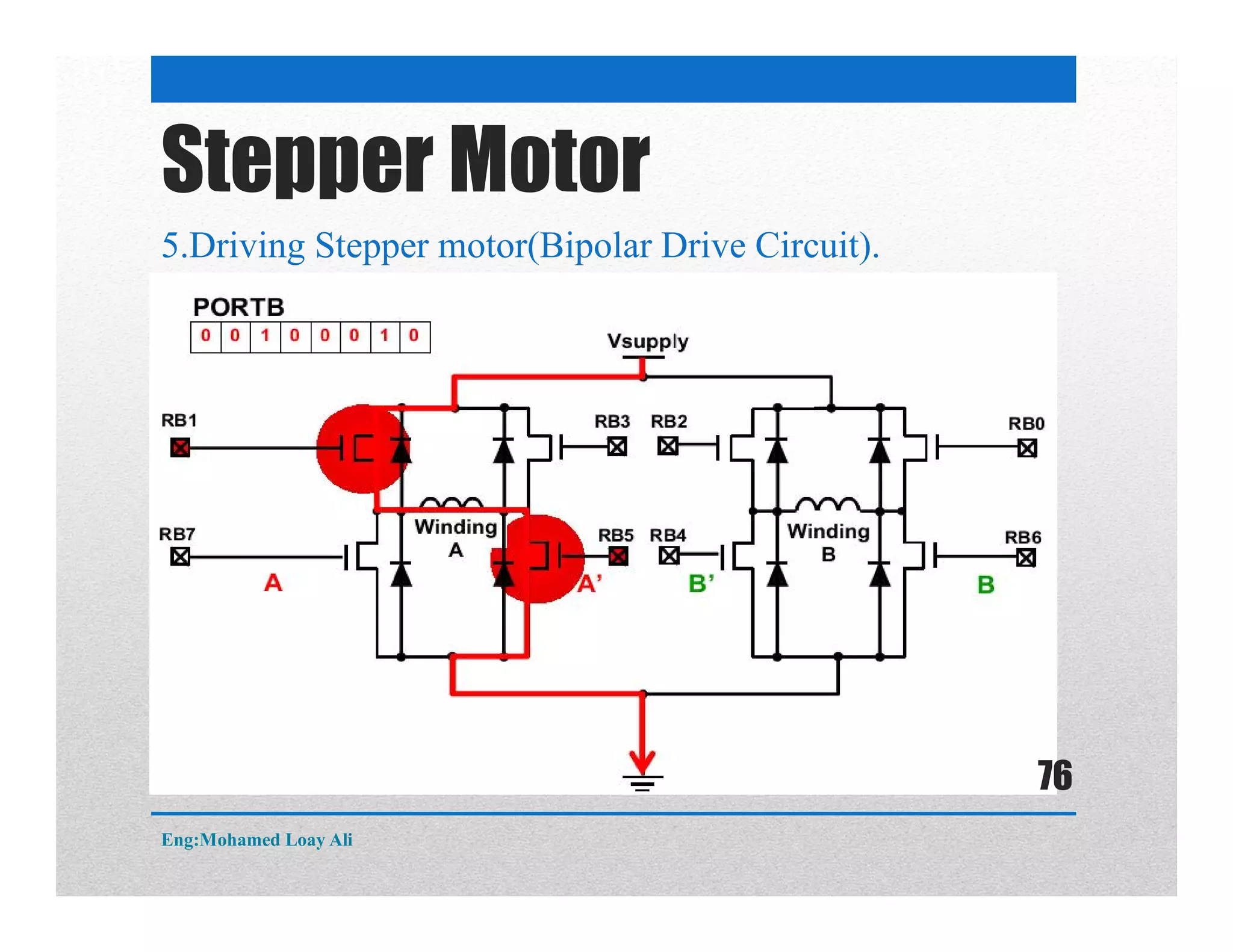
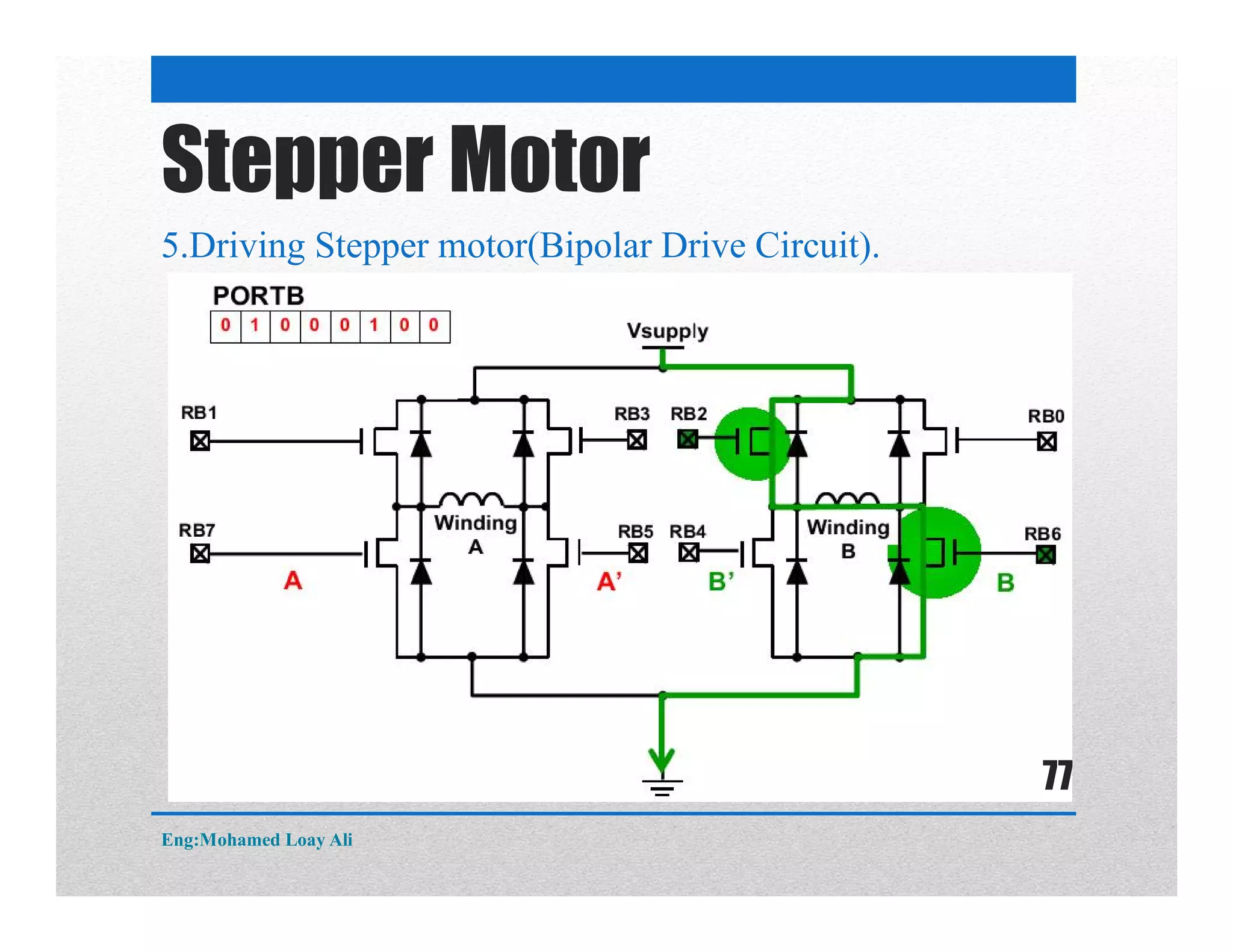
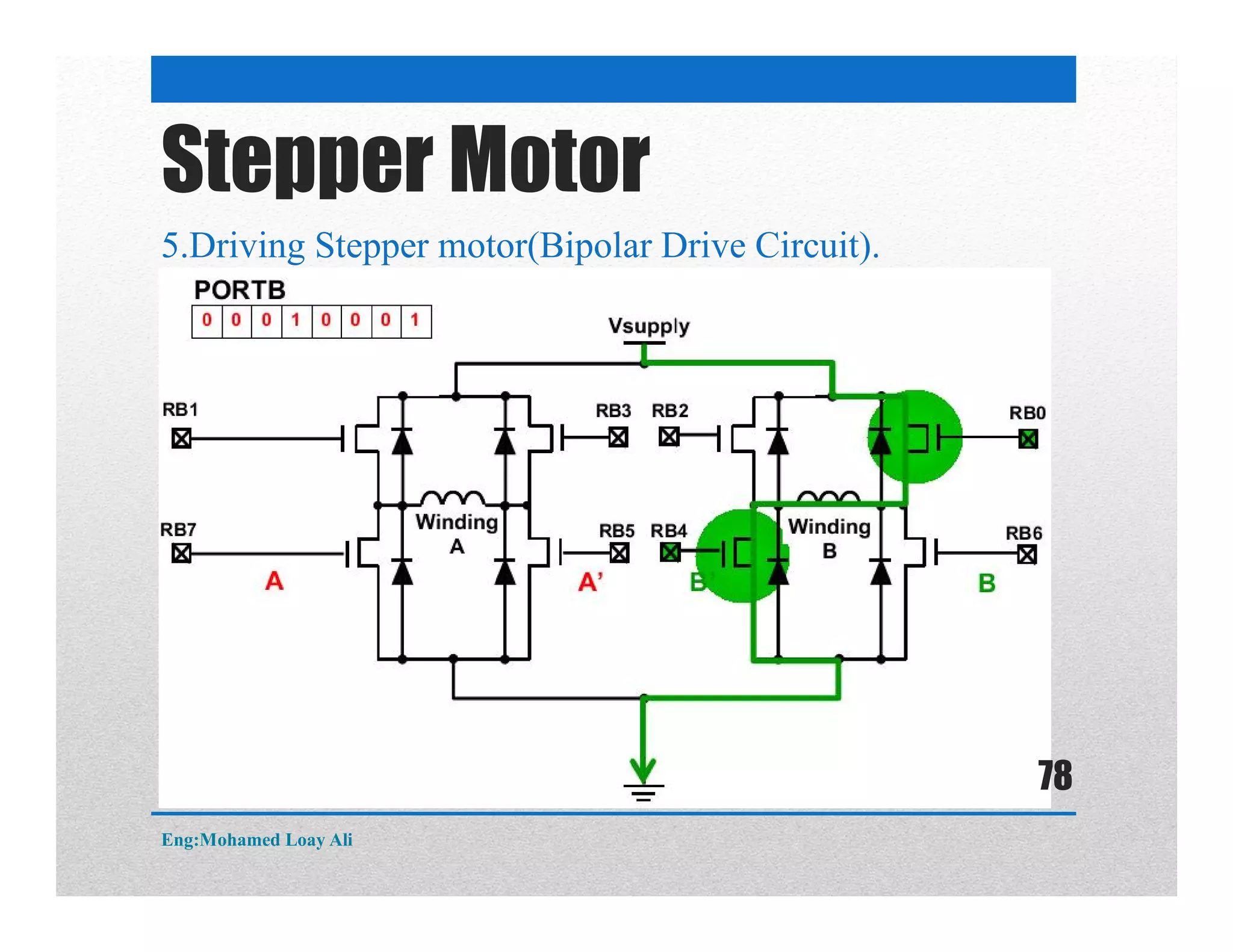
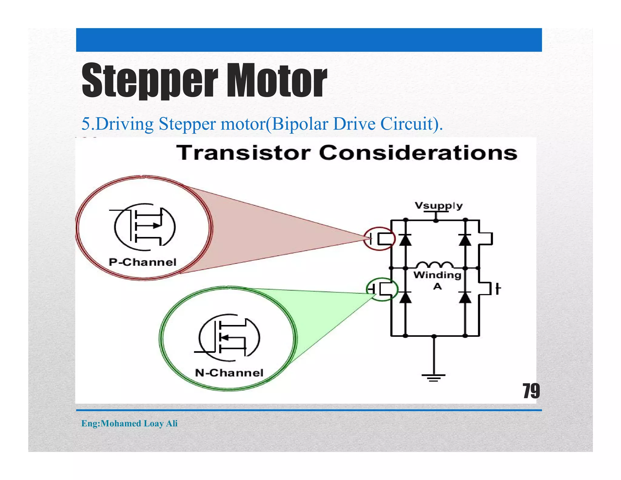
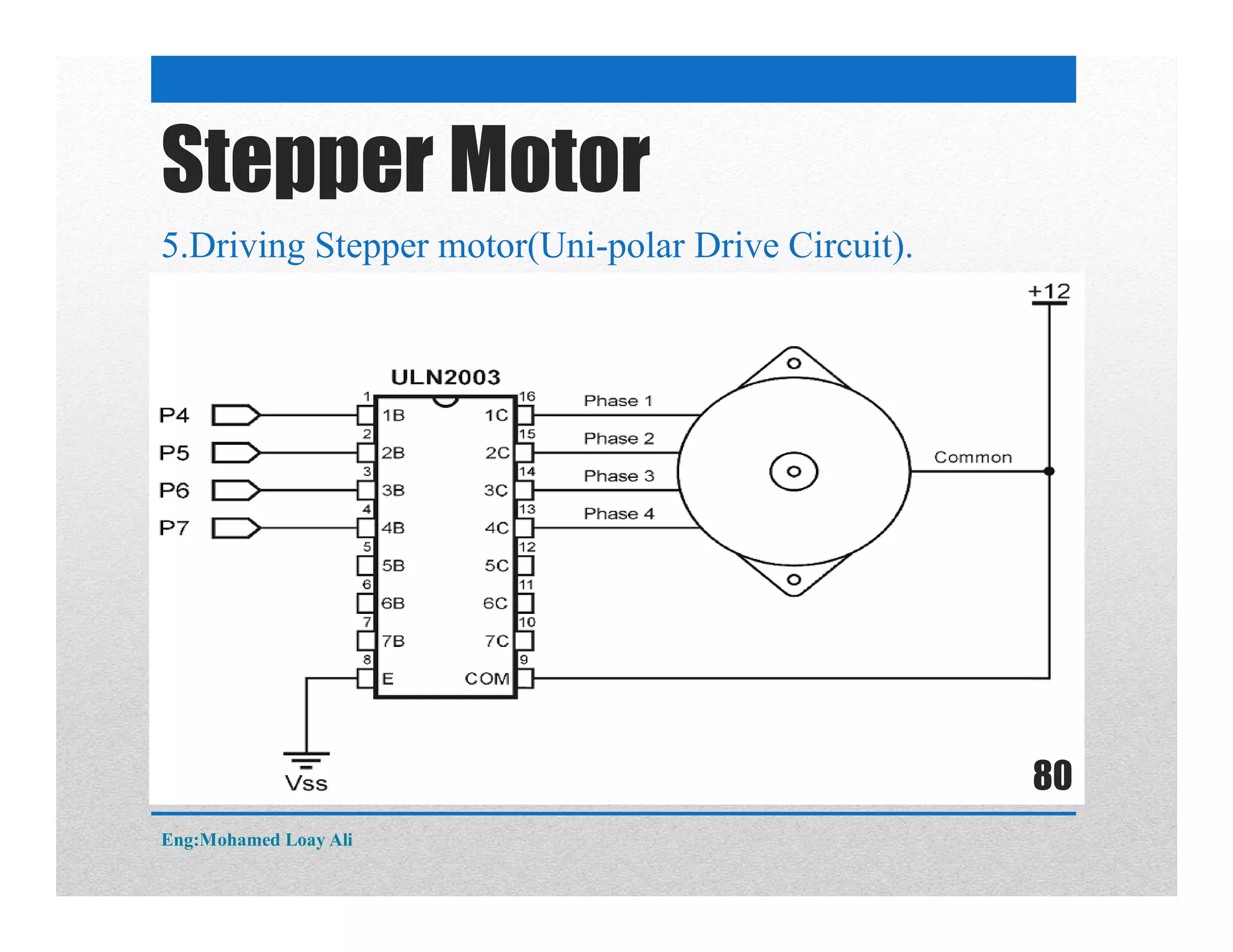
The document discusses various topics related to motor drive and PWM techniques. It covers DC motors, including their parameters and speed control using PWM. It also discusses stepper motors, including their basics, components, types, driving modes for unipolar and bipolar stepper motors, and drive circuits. PWM modes for 8-bit and 16-bit controllers are explained for both DC and stepper motor control applications.
2. Contents
DC Motor
1. Introduction to DC motor and its parameters.
2. PWM 8 bits modes (Fast PWM &Phase Correct).
3. PWM 16 bits modes (Fast PWM & Phase Correct).
4. Speed Control of DC motor.
Stepper motor.
1. Stepper motor basics.
2. Main Components of Stepper motor.
3. Types of Stepping Motors
4. Unipolar and Bipolar Stepper Motors
5. Driving Stepper motor.
Eng:Mohamed Loay Ali
2
3. DC motor
1. Introduction to DC motor and its parameters.
A direct current motor one of the most widely used motors.
By connecting the motor terminal to dc source it rotates in one direction,
and by reversing the polarity it rotates to the opposite direction.
The maximum speed of a dc motor is indicated with the rpm and is
given in the data sheet.
The dc motor control can be unidirectional or bidirectional as shown in
the following figure
Eng:Mohamed Loay Ali
3
4. DC motor
1. Introduction to DC motor and its parameters.
The speed of the motor depends on three factors
1) Load.
2) Voltage.
3) Current.
The rpm of the motor can be controlled by varying the voltage
terminals.
For a given fixed load a steady speed can be maintained by using
Pulse width modulation (PWM) to change the voltage across the DC
terminals.
Although the PWM has a fixed amplitude, it has a variable duty
cycle. That means the wider pulse the wider the higher the speed.
By varying the duty cycle the power fed to the motor speed is
changing as shown in the following
Eng:Mohamed Loay Ali
4
8. DC motor
PWM 8 bits modes : Fast PWM
Eng:Mohamed Loay Ali
8
9. DC motor
PWM 8 bits modes : Fast PWM
Eng:Mohamed Loay Ali
9
10. DC motor
PWM 8 bits modes : Fast PWM
Eng:Mohamed Loay Ali
10
11. DC motor
PWM 8 bits modes : Fast PWM
Eng:Mohamed Loay Ali
11
12. DC motor
PWM 8 bits modes : Fast PWM
Eng:Mohamed Loay Ali
12
13. DC motor
PWM 8 bits modes : Fast PWM
Eng:Mohamed Loay Ali
13
14. DC motor
PWM 8 bits modes : Fast PWM
Eng:Mohamed Loay Ali
14
15. DC motor
PWM 8 bits modes : Fast PWM
Eng:Mohamed Loay Ali
15
16. DC motor
PWM 8 bits modes : Fast PWM
The counter counts up like it does in the normal mode.
It counts up until it reaches its maximum value 0xFF.
Then it rolls over to from 0xFF to 0x00 ,it set the TOV
The fast PWM differs from the other PWM option by its single-slope operation.
In non-inverting Compare Output mode, the Output Compare (OC0x) is cleared
on the compare match between TCNT0 and OCR0x, and set at BOTTOM.
In inverting Compare Output mode, the output is set on compare match and
cleared at BOTTOM.
Eng:Mohamed Loay Ali
16
17. DC motor
PWM 8 bits modes :PWM 8 bits modes : Fast PWM
Eng:Mohamed Loay Ali
17
18. DC motor
For non-Inverted mode
For Inverted mode
PWM 8 bits modes : Fast PWM
Eng:Mohamed Loay Ali
18
19. DC motor
PWM 8 bits modes : Fast PWM
Eng:Mohamed Loay Ali
19
20. DC motor
PWM 8 bits modes : Phase Correct
The phase correct PWM mode (WGM02:0 = 1 or 5) provides a high resolution.
The counter counts repeatedly from BOTTOM to TOP and then from TOP to
BOTTOM. TOP is defined as 0xFF when WGM2:0 = 1and OCR0A when
WGM2:0 = 5
In non-inverting Compare Output mode, the Output Compare (OC0x) is cleared
on the com-pare match between TCNT0 and OCR0x while up counting, and set
on the compare match while down counting.
In inverting Output Compare mode, the operation is inverted. The dual-slope
operation has lower maximum operation frequency than single slope operation
Eng:Mohamed Loay Ali
20
22. DC motor
PWM 8 bits modes : Phase Correct
For non-Inverted mode
For Inverted mode
Eng:Mohamed Loay Ali
22
23. DC motor
PWM 8 bits modes : Phase Correct
Eng:Mohamed Loay Ali
23
24. DC motor
PWM 16 bits modes (Fast PWM & Phase Correct).
Speed Control of DC motor.
DO IT Yourself
Eng:Mohamed Loay Ali
24
25. Stepper Motor
1. Stepper motor basics.
Stepper Motor are motors that moves one step at a time.
A digital version of an electric motor
Each step is defined by a Step Angle
Eng:Mohamed Loay Ali
25
26. Stepper Motor
1. Stepper motor basics.
Relatively inexpensive
Ideal for open loop positioning control
Can be implemented without feedback
Minimizes sensing devices
Just count the steps!
Torque
Holds its position firmly when not turning
Eliminates mechanical brakes
Produces better torque than DC motors at lower speeds
Positioning applications
Eng:Mohamed Loay Ali
26
27. Stepper Motor
2.Main Components of Stepper motor.
Consists of
1.Stator:
Holds multiple
windings/phases
Eng:Mohamed Loay Ali
27
29. Stepper Motor
2.Main Components of Stepper motor.
Voltage applied to winding initiates current flow
Magnetic flux begins to flow
Eng:Mohamed Loay Ali
29
30. Stepper Motor
2.Main Components of Stepper motor.
Rotor rotates to minimize flux path (or reluctance)
Eng:Mohamed Loay Ali
30
31. Stepper Motor
3.Types of Stepping Motors
Permanent Magnet
Magnetic rotor
Variable Reluctance
Non-magnetic, geared rotor
Hybrid
Combines characteristics from PM and VR
Magnetic, geared rotor
Eng:Mohamed Loay Ali
31
36. 4.Unipolar and Bipolar Stepper Motors
Stepper Motor
Leads on each coil can
be brought out in two
ways:
−Each lead taken separately
−Bi-directional current flow
through entire winding
Eng:Mohamed Loay Ali
36
37. 4.Unipolar and Bipolar Stepper Motors
Stepper Motor
A center tap added
between the two leads
−Unidirectional current flow
in each ½ of winding
Unipolar
Eng:Mohamed Loay Ali
37
67. Stepper Motor
5.Driving Stepper motor(Unipolar half Step).
Center Tap
connected to
Ground or Voltage
Source.
Current flows in ½
winding at a time.
Eng:Mohamed Loay Ali
67