Downloaded 34 times

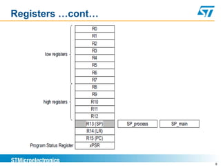
![Registers …cont…
Program Status Register (PSR)
Application PSR
N, C, Z, V, Q and GE[3-0] Condition flags
Interrupt PSR
Holds the exception number of the currently executed
exception
Execution PSR
T and ICI/IT bit fields
9](https://image.slidesharecdn.com/armtraining-160822035245/85/ARM-Cortex-M3-Training-9-320.jpg)

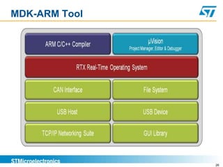
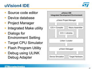

This document provides an overview of the ARM Cortex-M3 subsystem and its peripherals. It discusses the Cortex-M3 processor core and its features like the pipeline, instruction set, registers and exception handling. It also describes the peripherals like DMA, UART, timers and watchdog. The document outlines the development tools like uVision IDE and debugger. It discusses the software development flow including building, downloading and debugging programs on the target board.