The document contains 26 multiple choice questions about electromagnetic induction. The questions cover topics such as induced emf in coils, Lenz's law, and how changing magnetic flux induces currents. They provide examples of coils and conductors moving through magnetic fields to illustrate how induced currents are generated through electromagnetic induction.
A Project made for my School in the 10th Grade explaining the differences and working of AC and DC Generators.
Contents:
-Introduction
-Electromagnetic induction
-EMF- Electromotive Force
-Fleming’s Right Hand Rule
-Components of a Generator
*Rotor
*Armature
*Coil
*Stator
*Field electromagnets
*Brushes
-A.C. generators
-Commercial A.C generators
-DC generators
-Principle
-Working
-Differences between AC and DC
This document discusses inductive proximity sensors. It defines inductive proximity sensors as electronic devices that can detect metal objects without physical contact through the use of magnetic fields. It explains that inductive proximity sensors work by inducing eddy currents in nearby metal objects using a magnetic field, which are then detected. The document notes there are differences between shielded and non-shielded inductive sensors and provides examples of inductive sensor applications like position determination, camshaft interrogation, and use in wind power plants.
A detailed presentation on Photoconducting Cells - its design, construction and working presented as a semester assignment made possibly as a reference guide for engineering students.
A rectifier converts alternating current (AC) to direct current (DC) by only allowing current to flow in one direction. The presentation discusses half wave rectifiers, which use one diode and pass current during either the positive or negative half of the AC cycle. It also covers full wave rectifiers like the center tap and bridge rectifier, which use two or more diodes to pass current during both halves of the AC cycle, thereby doubling the output current compared to a half wave rectifier.
The document discusses Schottky barriers and contact resistance at metal-semiconductor junctions. Some key points:
1) A Schottky barrier forms at a metal-semiconductor junction and depends on the barrier height. The barrier height is influenced by the work functions but often does not follow predictions due to interface states.
2) Contact resistance is measured using the transmission line method, where resistance is measured across test structures with varying metal contact lengths. Specific contact resistance is calculated from these measurements.
3) Contact resistance is important to optimize in semiconductor devices and production. It is influenced by temperature and current effects at the metal-semiconductor interface.
This document discusses power electronic converters for DC drives. It outlines controlled rectifier fed and DC-DC converter fed DC drives. DC-DC converters allow obtaining a variable DC voltage from a fixed DC source using step-down and step-up choppers. Two-quadrant and four-quadrant control are described to allow motoring and braking in one or multiple quadrants. Closed-loop control with current and speed feedback is briefly discussed.
This document contains 69 multiple choice questions about basic electrical engineering and electronics. The questions cover topics such as superposition theorem, parallel and series circuits, transformers, motors, power measurement, semiconductors, and diodes. For each question there are 4 possible answers labeled A through D, and the correct answer is indicated.
Making a simple variable power supply.
Power supply applications.
Ac and Dc current defintions.
Half wave and full wave rectifier.
Power supply circuit.
Used tools.
Working steps.
Testing.
This document discusses inductors, which are passive electronic components that store electrical energy as magnetic energy. It defines an inductor as a coil of conducting material, typically copper wire, wrapped around a core. The more turns of the coil and the stronger the magnetic field generated. Inductors are used in applications such as filters, sensors, and transformers. They work by generating a magnetic field when electricity flows through the coil.
Unit 03 Construction & Operation of Watt meter & Energy meterPremanandDesai
An induction watt-hour meter measures electrical energy consumption by using two electromagnets to induce eddy currents in an aluminum disk and rotate it. The disk's rotation is proportional to energy used and is registered to indicate kilowatt-hours. It works by using a series coil carrying load current and a shunt coil carrying voltage-proportional current to generate a rotating magnetic field. This field interacts with eddy currents in the disk to provide a driving torque while a brake magnet provides a braking torque proportional to disk speed. Errors can occur due phase shifts or other issues, but the meter can be adjusted to ensure accurate readings.
The document discusses recent trends in photonic devices. It begins by defining optics and photonics, and describes some applications of photonics including information technology, healthcare, sensing, lighting and displays. It then explains that photonic devices manipulate or detect light, providing examples like lasers, LEDs and solar cells. The document goes on to discuss latest trends like nanophotonics using graphene, carbon nanotubes and photonic crystals. It also covers silicon photonic devices using silicon-germanium transistors and germanium-tin phototransistors. In conclusion, it predicts future applications of photonics in areas like e-paper, solar panels and light-emitting fabrics.
This document discusses conductors, insulators, and semiconductors. It explains that semiconductors are metalloids that have a small band gap between the valence and conduction bands, allowing electrical conductivity to increase with temperature. Semiconducting elements like silicon and germanium form the basis of solid state electronic devices. Doping semiconductors with other elements can produce either n-type or p-type materials, and joining n-type and p-type materials creates a p-n junction that can function as a rectifier. The transistor was invented in 1947 at Bell Labs and has revolutionized electronics, with integrated circuits continuing to shrink in size following Moore's Law.
This document provides an overview of Chapter 2 on Direct Current (DC) Circuits from the course BEKG 1123 Principles of Electric and Electronics. The chapter covers DC sources, Ohm's law, power and energy, resistors, capacitors, inductors, and circuit analysis techniques including Kirchhoff's laws, series and parallel circuits, and node/mesh analysis. The key topics include defining DC circuits, calculating current, voltage, resistance, conductance and power using Ohm's law, the characteristics and functions of resistors, capacitors and inductors, and analyzing electrical circuits.
Lecture 1 introduction of Power Electronicsaadesharya
The document provides an introduction to the course on Power Electronics. It defines power electronics as the field that utilizes electronic power devices to convert one form of electric power to another with proper control. The document discusses the objectives of the course which is to acquaint students with fundamental power electronics concepts and switches. It also provides a block diagram of typical power electronics systems showing the power converter and controller that work together to provide controlled power to different loads.
Speed control in 3 phase induction motorKakul Gupta
Speed control in induction motors is required for efficient operation
Various methods of speed control through semiconductor devices:
1. Stator voltage control
2. Stator frequency control
3. Stator voltage control
4. Stator current control
5. Static Rotor Resistance Control
6. Slip Energy Recovery Control
This document summarizes the components and working of a simple AC generator. It consists of a field magnet that produces a magnetic field, an armature coil that rotates in this field, slip rings to carry the changing current from the rotating coil, and brushes that transfer this current to an external circuit. As the coil rotates, it cuts the magnetic flux which induces an electromotive force based on Faraday's law of induction, causing an alternating current to be generated. Some applications of AC generators include charging batteries in vehicles, powering diesel locomotives, and generating electricity on boats.
This document provides an overview of key electrical concepts including:
- Voltage is the potential difference measured in volts that causes current to flow. Current is the rate of flow of electric charge measured in amperes.
- Ohm's law defines the relationship between voltage, current, and resistance in a circuit. Power is defined as voltage multiplied by current and describes the rate of energy transfer.
- Common circuit components are described including resistors, capacitors, diodes, transistors, integrated circuits, and how they are connected using printed circuit boards. Direction of electron and conventional currents are also discussed.
Semiconductors are substances that can conduct electricity under some conditions but not others. They have resistivity between metals and insulators. There are two types - elemental semiconductors consisting of a single element like silicon or germanium, and compound semiconductors consisting of multiple elements like indium phosphide. In semiconductors, energy levels split into permitted energy bands separated by a forbidden energy gap when atoms are close together. The valence band is filled with electrons and the conduction band above it is empty or partially filled, with a gap between them through which electrons need energy to move.
The magnetically sensitive transistor (also known as the spin transistor or spintronic transistor—named for spintronics, the technology which this development spawned), originally proposed in 1990 and currently still being developed, is an improved design on the common transistor invented in the 1940s. The spin transistor comes about as a result of research on the ability of electrons (and other fermions) to naturally exhibit one of two (and only two) states of spin: known as "spin up" and "spin down". Unlike its namesake predecessor, which operates on an electric current, spin transistors operate on electrons on a more fundamental level; it is essentially the application of electrons set in particular states of spin to store information.
1. Light interference occurs when two light waves overlap and their amplitudes combine according to the principle of superposition.
2. Constructive interference occurs when the light waves are in phase, resulting in enhanced intensity. Destructive interference occurs when light waves are out of phase, cancelling each other out.
3. Interference patterns from thin films can be observed by overlapping the light waves that are reflected or transmitted through the film. The optical path difference between the waves determines whether constructive or destructive interference occurs.
This document discusses metal-semiconductor interfaces, specifically rectifying Schottky junctions and non-rectifying ohmic contacts. It provides energy band diagrams to illustrate how Schottky junctions form a barrier under reverse bias but allow thermionic emission under forward bias, while ohmic contacts have matching work functions allowing current to flow freely. Applications of Schottky diodes mentioned include RF mixing and solar cells.
The document describes a Magneto-Optic Current Transducer (MOCT) which uses the Faraday effect to measure electric current. It consists of an optical sensor head near the current carrying conductor, connected via fiber optic cables to a signal processing unit. The sensor rotates the polarization of light passing through it based on the current, which is detected and converted to an output signal. Key advantages over conventional transformers include simpler insulation, immunity to EMI, and wider frequency response.
This document summarizes lecture material from an Electronic Devices course taught by Arpan Deyasi at RCC Institute of Information Technology in Kolkata, India. The document discusses quasi-Fermi levels, generation and recombination of carriers, and the continuity equation as it relates to excess carriers in semiconductors. Key points include definitions of quasi-Fermi levels for n-type and p-type materials, equations describing generation and recombination rates, and the continuity equation modeling carrier transport and generation/recombination processes in non-uniformly doped semiconductors.
1. The document discusses a case study on simulating a step-up transformer in MATLAB.
2. A step-up transformer increases voltage by having more turns in the secondary coil than the primary coil, inducing a higher voltage on the secondary side.
3. The case study involves simulating a step-up transformer in MATLAB, obtaining the simulation results, and analyzing the technical specifications and applications of step-up transformers.
The document discusses the cathode ray oscilloscope (CRO). It describes the CRO's components including the cathode ray tube with electron gun and deflection plates, and how it is used to display voltage waveforms. The document also discusses applications of the CRO such as measuring frequency using Lissajous patterns and measuring phase difference.
this presentation gives a clear idea of how the servo motor and servo drive working explained in detail and attached video have a clear idea of how servo motor works......enjoy, i hope you will like this.... :)
Electromagnetism ap multiplechoiceanswers2011 _1_Vladimir Morote
This document contains multiple choice questions about circuits and electricity concepts. It includes questions about:
- Equivalent resistances of circuits with resistors in series and parallel
- Current, voltage, and power calculations in circuits
- Capacitors and capacitance
- Kirchhoff's laws and circuit analysis
- Electromagnetism, magnetic fields, and induced currents
The document discusses a workshop organized by KV Andrews Ganj to prepare sample higher-order thinking (HOT) questions for Class XII Physics. [1] A two-day workshop was held in July 2008 with 10 Physics teachers from various KVs participating. [2] The teachers worked to computerize chapter-wise sample HOT questions for CBSE Class XII Physics. [3] The principal expresses that this material will help students and teachers perform better in board exams, while noting that teachers can prepare additional questions to improve student competency.
J2 Physics 2008 prelim electromagnetic induction (questions + ans for mcq)John Jon
The document contains 26 multiple choice questions about electromagnetic induction. The questions cover topics such as induced emf in coils, Lenz's law, and factors that affect induced current. They provide examples of coils and circuits experiencing changing magnetic fields from magnets and electric currents. The document tests understanding of fundamental concepts in electromagnetic induction.
The document provides:
1) An introduction to the College Board, outlining its mission to connect students to college success and the programs and services it offers.
2) Copyright information and permissions for use of College Board materials.
3) The table of contents for the 2006 AP Physics B Free-Response Questions, including the questions, constants and conversion factors, equations, and diagrams to be used for the exam.
Compilation of questions on electromagnetism (questions only + ans for mcq)John Jon
1. A velocity selector is used to obtain an electron beam with a kinetic energy of 250 eV. Electrons with higher kinetic energies will pass through plate X, while electrons with lower kinetic energies will be deflected by plate Y.
2. When a current passes through a vertical wire PQ, a compass placed next to it may point in any of the four directions shown in the diagrams.
3. A uniform magnetic field applied in the same direction as an electric field maintaining a negatively charged plastic sphere at a constant height will have no effect on the sphere.
This document discusses Belbin's Team Role Model, which identifies 9 common team roles that individuals tend to adopt: Shaper, Implementer, Completer-Finisher, Coordinator, Team Worker, Resource Investigator, Plant, Monitor-Evaluator, and Specialist. These roles are categorized into Action, People and Thought orientations. Understanding individual roles helps create balanced teams by ensuring necessary skills are covered and weaknesses addressed. The document provides guidance on using Belbin's model to analyze team roles and balance for improved performance. However, it cautions not to rely too heavily on the model and to consider other factors impacting team success.
Las asignaturas propuestas para los primeros cuatro semestres de arquitectura incluyen: Arquitectura y lugar, Dibujo artístico, Percepción y representación gráfica, Fundamentos estructurales, Planimetria Arquitectonica, Espacio y Materialidad, Estética de la Arquitectura y Modelado y Estructura.
For grades eight or nine. Gives a brief overview of the characteristics of narration and has a super Youtube video from Flocabulary [http://www.youtube.com/user/FlocabularyYT} which definitely appeals to young learners.
The document discusses key facts about the Earth-Moon system. It begins by providing scale comparisons showing that the Moon is about 1/4 the width of Earth and its radius is 1080 miles. It also notes that the Moon's gravity is about 1/6 that of Earth. Next, it explains that because the Moon rotates on its axis in the same time it takes to revolve around Earth (27.3 days), we only ever see one hemisphere of the Moon from Earth. It concludes by stating the Moon's elliptical orbit around Earth ranges from 360,000 to 406,000 km away.
The document discusses light decay in both the real world and in 3D virtual worlds. In the real world, light intensity decreases with distance from the source due to the light waves spreading out. In virtual worlds, different decay models can be used, including linear decay where intensity decreases directly with distance, quadratic decay where it decreases with the square of the distance similar to real light, and cubic decay where it decreases faster. Additional techniques like decay regions and intensity curves allow further control over how light intensity changes over distance.
Li & Fung Ltd is a global supply chain company founded in 1906 in Guangzhou, China that coordinates product design, sourcing, production, and quality assurance for major retailers. It has expanded to over 26,000 employees working across 40 countries with a network of over 15,000 suppliers. The company pioneered the philosophy of managing global supply chains and allowing customers to source products closer to various markets. It performs higher value tasks like design and quality control in Hong Kong while outsourcing lower value production to optimal locations around the world.
This document provides an overview of the Compass Treasury system. It describes the system's comprehensive coverage of financial products across multiple currencies and locations. It also highlights key features like user-defined business rules, integrated accounting and risk management modules, hierarchical consolidation, compliance monitoring, audit trails, and segregation of duties. The system architecture is designed for flexibility across different deployment environments and uses common programming languages and database platforms.
This document provides an introduction to a lesson on communication skills for healthcare providers. It covers key vocabulary words used in healthcare, the importance of communication skills like listening, speaking, writing and body language. It also discusses the three parts of the communication process - the sender, the message, and the receiver. Later sections provide examples and skills checks to practice effective listening, speaking, writing and understanding nonverbal communication.
Dimensions of business to consumer (b2 c) systems success in kuwaitsan18
This document summarizes an academic journal article that tests an enhanced model of business-to-consumer (B2C) e-commerce systems success in Kuwait. The study builds on prior research by Wang (2008) that applied the Delone and McLean information systems success model to e-commerce. The proposed model adds several improvements, including a multidimensional view of system quality, conceptualizations of both monetary and non-monetary value, and e-commerce-specific factors. The model was tested using 288 experienced B2C consumers in Kuwait and the results largely support the hypothesized relationships in the model. A key finding is that while service quality influences perceived value, it does not impact user satisfaction in the Arab context,
Este documento discute a transmissão de dados em redes de computadores. Ele aborda três pontos principais: 1) a definição de transmissão de dados e seus elementos básicos como fonte, informação, veículo de transmissão e receptor; 2) as diferentes tecnologias de transmissão como fios de cobre, fibras óticas, rádio e satélites; 3) a diferença entre informação analógica e digital e as tecnologias analógicas e digitais de transmissão.
This document is a reference form for prospective volunteers of Hospice of Dayton. The form requests information from references about how long they have known the candidate, their relationship to the candidate, their assessment of the candidate's interpersonal skills, and ratings of the candidate's dependability, emotional skills, adaptability, initiative, communication skills, and interpersonal skills. References are also asked if the candidate should not volunteer, if the candidate can make a contribution, if they would entrust loved ones to the candidate, and if the reference can be contacted for more information.
1. The document discusses electromagnetic concepts such as magnetic flux density, magnetic fields due to different current carrying conductors, and the torque experienced by a coil in a magnetic field.
2. Questions are provided about defining magnetic flux density, sketching magnetic field patterns, calculating torque on a coil, and ensuring the magnetic field is parallel to the coil plane.
3. Key concepts covered include magnetic fields, torque, magnetic flux density, and its SI unit of tesla.
www.entranceindia.com provides JEE Main 2015 model papers including all subjects such as Physics, Chemistry, Mathematics along with their Sample papers, Practice Test Series and Past exam papers in online as well as DVD mode. For more information about jee main 2015 please visit our site www.entranceindia.com
Rotating magnetic fields are produced in induction motors by three-phase stator windings that are mechanically displaced by 120 degrees. The stator produces a rotating magnetic field that causes the rotor to turn. Induction motors have a stationary stator and a revolving rotor made of laminated steel. The rotor can be either a squirrel cage type with conducting bars in slots or a wound rotor type with three-phase windings and slip rings. The rotating magnetic field induces currents in the rotor that generate torque causing the rotor and attached load to rotate.
This document contains a sample test for the JEE (Main) 2015 exam. It includes 42 multiple choice questions across various subjects like physics, chemistry, and mathematics. The questions cover topics such as capacitors, radioactive decay, organic reactions, thermodynamics, coordination compounds, and molecular orbitals.
The document discusses direct current (DC) motors and generators. It describes their construction and operating principles. DC motors have stator poles that create a magnetic field when energized by DC current. The rotor is connected to commutator segments through brushes, allowing DC current to flow through the rotor coils. The interaction between the magnetic field and current produces rotation. DC generators operate similarly but with the rotor driven by an external force, inducing voltage in the coils. The commutator reverses current direction to maintain constant voltage output as the coils rotate.
The document describes the construction and operation of DC machines. It contains the following key points:
1. A DC machine consists of a stator with poles that produce a magnetic field and a rotor with coils connected by a commutator. The interaction between the magnetic field and current in the rotor coils causes the rotor to rotate.
2. In a DC motor, the stator poles are supplied with DC current to generate a magnetic field. The rotor coils are also supplied with DC current, causing the rotor to rotate due to Lorentz forces. The commutator reverses the current to maintain rotation.
3. In a DC generator, a mechanical input rotates the rotor coils in the stator's
This document provides instructions for experiments on power semiconductor switches and switch-mode power converters to be carried out by students. The experiments involve testing an SCR using a multimeter, studying the turn-on and turn-off states of an SCR, and effects of gate current. Students will also study the switching parameters of a BJT and build a buck converter circuit. Performance in the experiments, teamwork, and learning attitude will contribute towards marks. Students are advised to read the instructions fully before conducting the experiments.
Electrical Power Systems 3 phase apparatusMubarek Kurt
This document discusses 3-phase power apparatus and provides information on various electrical machine concepts including:
- The basic concept of magnetic fields and flux in electrical machines
- The rotating components and applications of rotating machines like generators, motors, and alternators
- The structures and operating principles of different types of AC and DC machines including synchronous and induction machines
It also covers topics like induced voltages and torque in electrical machines, power flows and losses, efficiency, voltage regulation, and speed regulation.
- DC generators and motors operate using the principle of electromagnetic induction. When a conductor moves through a magnetic field, an electromotive force (emf) is induced in the conductor.
- The basic components of a DC generator are a magnetic field (produced by poles and field windings) and a conductor (armature) that rotates within the magnetic field. This motion induces an emf in the armature.
- A commutator is used to convert the alternating current from the armature into direct current that can be supplied to a load. Brushes make contact with the commutator segments to carry the output current.
The document discusses the operating principles of DC motors and generators. It explains that in a DC motor, a commutator produces alternating currents from a DC power source to create a rotating magnetic field in the rotor. It also describes how the interaction between the rotor's magnetic field and the stator's magnetic field causes the rotor to rotate. In generators, a rotating coil cutting magnetic lines of force induces an AC voltage that is rectified by the commutator into a DC voltage.
Realization of Current-mode Quadrature Oscillator Based on Third Order TechniqueIDES Editor
The document presents a current-mode quadrature oscillator circuit based on third order technique. The proposed circuit uses a current controlled current conveyor transconductance amplifier (CCCCTA) and operational transconductance amplifier (OTA) as active elements. It provides quadrature output currents from high impedance terminals. The oscillation condition and oscillation frequency can be electronically controlled independently via input bias currents. Simulation results show the circuit operates as expected with a power consumption of approximately 5.12mW.
This document provides information on DC machines, including their construction and operation principles. It describes how a DC machine can operate as either a motor or a generator. The rotor has coils wound in slots with ends connected to segments of a commutator. Brushes pressed against the commutator switch the current direction in the coils to maintain rotation. In a motor, the interaction between the magnetic field and current in the rotor coils produces a torque. In a generator, rotation of the coils in the magnetic field induces a voltage that is transmitted through the commutator.
Construction and components of DC Machine – Principle of operation – Lap and wave windings-EMF equations– circuit model – armature reaction –methods of excitationcommutation – interpoles compensating winding –characteristics of DC generators.
1) The document discusses the fundamentals of DC machinery, including the simplest DC machine consisting of a single rotating loop of wire. It describes how a voltage is induced in the loop due to rotation in a magnetic field and how a commutator can be used to produce DC voltage and current from the alternating voltage in the loop.
2) It then discusses a DC machine with a wound armature core and multiple loops of wire. It explains the commutation process which converts the AC voltages and currents in the rotor to DC voltages and currents at the machine terminals.
3) Finally, it illustrates commutation in a simple 4-loop DC machine, showing the induced voltages in each loop segment at a particular time step
The document summarizes key aspects of brushless DC motors (BLDC). It describes that a BLDC motor uses an integrated inverter to produce an AC signal that drives the motor, with the rotor and stator magnetic fields rotating at the same frequency with no slip. It then discusses the construction of a BLDC motor, including its stator with coils to generate a magnetic field and its permanent magnet rotor. The working principle is also summarized, where the rotor position sensor provides information to commutate the coils in sequence to generate rotation. Advantages like increased reliability and efficiency are contrasted with disadvantages like higher cost and need for complex drive circuitry. Applications mentioned include consumer goods and vehicles.
The document discusses the silicon controlled rectifier (SCR), a three-terminal semiconductor device that acts as a controlled switch. It can rectify AC to DC and control the amount of power delivered to a load. The SCR combines the functions of a rectifier and transistor. Key points include:
1) An SCR has two states - it either does not conduct or conducts heavily, behaving like a switch.
2) It is turned on by applying a small positive voltage to the gate, as the breakover voltage is usually much higher than the supply voltage.
3) To turn it off, the supply voltage must be reduced to zero to stop conduction.
IRJET- Design and Implementation of Isolated Multi-Output Flyback ConverterIRJET Journal
This document describes the design and implementation of an isolated multi-output flyback converter. A flyback converter uses a single switch and transformer to provide isolated output voltages from an input source. The designed converter uses a toroidal transformer with multiple secondary windings to generate multiple isolated output voltages at fixed levels. Simulation results and specifications for the transformer, switch, and outputs are provided. The flyback converter provides an efficient and low-cost solution for applications requiring multiple isolated low-power DC outputs.
1) A DC generator produces direct current through electromagnetic induction. When a conductor moves through a magnetic field, an electromotive force (EMF) is induced in the conductor.
2) The basic components of a DC generator are magnetic poles and conductors that rotate within the magnetic field.
3) In a single loop DC generator, an EMF is induced in the sides of a rotating rectangular conductor loop as it cuts through the magnetic flux lines. The loop is connected to brushes to output a direct current.
1) This document discusses the course "Electric Machines" which introduces the theory, operation, and performance of electrical machines and motors. It covers topics like DC motors, power transformers, and AC induction motors.
2) The course is evaluated based on a final exam worth 70% and classwork worth 30%, which includes a midterm exam, reports, and attendance.
3) Chapter 1 introduces electrical machines and drive systems, including definitions, classifications, voltage and torque equations, and the primitive machine model to explain basic operation of motors and generators.
Similar to Solutions for electromagnetic induction (20)
The document discusses various concepts related to waves including:
1. The amplitude of a wave is inversely proportional to its distance from the source. When amplitude doubles, distance halves.
2. Resonance frequencies of an open organ pipe are calculated based on quarter and three quarter wavelengths.
3. For three different waves, the ratios of their frequencies and wavelengths are given.
4. The detection of waves depends on the number of compressions and rarefactions detected per unit time.
5. Malus' law describes how the intensity of polarized light emerging from polarizers depends on the angle between their polarization axes.
1. When two waves meet at a point in space, their amplitudes add vectorially. Constructive interference occurs when the path difference is an integral multiple of the wavelength, producing loud sounds. Destructive interference occurs when the path difference is an odd multiple of half the wavelength, producing soft sounds.
2. As frequency increases, wavelength decreases. This causes the positions of constructive and destructive interference to shift towards the central axis as the microphone passes through them.
3. Increasing the slit separation in a double-slit experiment doubles the fringe separation in the interference pattern. The slit width does not affect fringe separation but decreases intensity.
1. The document contains questions about wave interference and diffraction concepts.
2. It includes multiple choice questions about wave superposition, diffraction gratings, and interference patterns.
3. Diagrams are provided with some questions to illustrate wave concepts like path differences and interference maxima.
1. The document provides solutions to oscillation problems involving simple harmonic motion (SHM).
2. It examines the oscillations of objects submerged in liquids and determines forces, pressure, and displacement using concepts of SHM.
3. Damped oscillations and forced oscillations driven by external periodic forces like water waves are also analyzed in the solutions.
The document contains 23 multiple choice questions related to oscillations and simple harmonic motion. The questions cover various topics including:
1) Calculating maximum velocity, period, frequency, and amplitude for objects undergoing SHM.
2) Distinguishing between damped and forced oscillations.
3) Relating kinetic energy, potential energy, restoring force, and displacement for oscillating systems.
4) Applying concepts of SHM to real world examples like floating blocks, swinging pendulums, and vibrating plates.
Lasers & semiconductors 2008 prelim solutionsJohn Jon
Electrons and holes are urged towards the junction region when the diode is in forward bias. This results in the reduction of the depletion region, thus allowing a current to flow. When a p-d is applied across a p-n junction diode in the forward bias mode, the width of the depletion layer decreases, allowing charge carriers to flow more easily across the junction. In reverse bias mode, the depletion layer width increases, preventing charge flow and making the diode act as an open switch.
J2 Physics 2008 Lasers & semiconductors prelim questions John Jon
Population inversion refers to a situation where the number of atoms in an excited higher energy state exceeds the number of atoms in a lower energy state. This condition is necessary to achieve laser action through stimulated emission. When population inversion is present, incident photons cause stimulated emission of photons of the same frequency and phase, leading to amplification of the light beam in the laser cavity.
J2 Physics 2008 prelim solutions Alternating current John Jon
The document lists a series of letters and numbers. It then provides 3 short paragraphs about: 1) How alternating voltage can be stepped up or down with little power loss using transformers compared to direct voltage; 2) A calculation showing a step-up transformer with a turn ratio of 2 taking an input of 120V at 8.33A RMS to an output of 1000V; 3) Mentions overhead power lines are cheaper to install and maintain than underground lines but can be blown against buildings in windy conditions.
J2 Physics 2008 prelim questions (Alternating current) John Jon
1. An AC generator produces a sinusoidal voltage. If the frequency is increased from 20 Hz to 30 Hz and the magnetic flux density is reduced, the peak output voltage will be 1.6 V.
2. If a 2.0 Ω resistor is connected to an AC supply with a peak voltage of 10 V across it, the RMS current flowing through the resistor is 5.0 A.
3. A full-wave rectified waveform would be seen on an oscilloscope connected across a resistor in a circuit with 4 diodes and an AC supply, if one of the diodes is removed.
This document contains 30 multiple choice questions about wave properties and behaviors. The questions cover a range of topics including:
- Characteristics of progressive and stationary waves
- Interference and superposition of waves
- Speed, frequency, wavelength and amplitude of waves
- Types of electromagnetic waves and their properties
- Reflection, refraction, and polarization of light
- Sound waves and resonance in pipes and tubes
JC H2 Physics Formula List/Summary (all topics)John Jon
Some of the concepts might be out of syllabus but I believe most of it is still relevant. It is a very concise summary containing mostly formulas and the Laws that govern Physics. This was done by a Raffles Institution student. I hope you will find this beneficial!
H1 Econs Macroeconomic problems and management Essay QuestionJohn Jon
This is an A level H1 econs essay question(economic growth and unemployment) taken from a good junior college's tutorial. The solution was compiled by me. Enjoy!
- A parachutist falling at constant velocity has a drag force equal to their weight due to the net force being zero.
- Newton's second law and free body diagrams are used to analyze forces on objects like cars and boxes on slopes.
- Impulse is used to relate average force and change in momentum to analyze collisions over short periods of time.
Chapter 2 Governance In Singapore Social Studies NotesJohn Jon
This is my self compiled notes of Chapter 2 : Governance in Singapore of the Upper Secondary Social Studies Textbook. I hope my notes will benefit you.
Goodbye Windows 11: Make Way for Nitrux Linux 3.5.0!SOFTTECHHUB
As the digital landscape continually evolves, operating systems play a critical role in shaping user experiences and productivity. The launch of Nitrux Linux 3.5.0 marks a significant milestone, offering a robust alternative to traditional systems such as Windows 11. This article delves into the essence of Nitrux Linux 3.5.0, exploring its unique features, advantages, and how it stands as a compelling choice for both casual users and tech enthusiasts.
Let's Integrate MuleSoft RPA, COMPOSER, APM with AWS IDP along with Slackshyamraj55
Discover the seamless integration of RPA (Robotic Process Automation), COMPOSER, and APM with AWS IDP enhanced with Slack notifications. Explore how these technologies converge to streamline workflows, optimize performance, and ensure secure access, all while leveraging the power of AWS IDP and real-time communication via Slack notifications.
How to Get CNIC Information System with Paksim Ga.pptxdanishmna97
Pakdata Cf is a groundbreaking system designed to streamline and facilitate access to CNIC information. This innovative platform leverages advanced technology to provide users with efficient and secure access to their CNIC details.
Alt. GDG Cloud Southlake #33: Boule & Rebala: Effective AppSec in SDLC using ...James Anderson
Effective Application Security in Software Delivery lifecycle using Deployment Firewall and DBOM
The modern software delivery process (or the CI/CD process) includes many tools, distributed teams, open-source code, and cloud platforms. Constant focus on speed to release software to market, along with the traditional slow and manual security checks has caused gaps in continuous security as an important piece in the software supply chain. Today organizations feel more susceptible to external and internal cyber threats due to the vast attack surface in their applications supply chain and the lack of end-to-end governance and risk management.
The software team must secure its software delivery process to avoid vulnerability and security breaches. This needs to be achieved with existing tool chains and without extensive rework of the delivery processes. This talk will present strategies and techniques for providing visibility into the true risk of the existing vulnerabilities, preventing the introduction of security issues in the software, resolving vulnerabilities in production environments quickly, and capturing the deployment bill of materials (DBOM).
Speakers:
Bob Boule
Robert Boule is a technology enthusiast with PASSION for technology and making things work along with a knack for helping others understand how things work. He comes with around 20 years of solution engineering experience in application security, software continuous delivery, and SaaS platforms. He is known for his dynamic presentations in CI/CD and application security integrated in software delivery lifecycle.
Gopinath Rebala
Gopinath Rebala is the CTO of OpsMx, where he has overall responsibility for the machine learning and data processing architectures for Secure Software Delivery. Gopi also has a strong connection with our customers, leading design and architecture for strategic implementations. Gopi is a frequent speaker and well-known leader in continuous delivery and integrating security into software delivery.
Threats to mobile devices are more prevalent and increasing in scope and complexity. Users of mobile devices desire to take full advantage of the features
available on those devices, but many of the features provide convenience and capability but sacrifice security. This best practices guide outlines steps the users can take to better protect personal devices and information.
Securing your Kubernetes cluster_ a step-by-step guide to success !KatiaHIMEUR1
Today, after several years of existence, an extremely active community and an ultra-dynamic ecosystem, Kubernetes has established itself as the de facto standard in container orchestration. Thanks to a wide range of managed services, it has never been so easy to set up a ready-to-use Kubernetes cluster.
However, this ease of use means that the subject of security in Kubernetes is often left for later, or even neglected. This exposes companies to significant risks.
In this talk, I'll show you step-by-step how to secure your Kubernetes cluster for greater peace of mind and reliability.
For the full video of this presentation, please visit: https://www.edge-ai-vision.com/2024/06/building-and-scaling-ai-applications-with-the-nx-ai-manager-a-presentation-from-network-optix/
Robin van Emden, Senior Director of Data Science at Network Optix, presents the “Building and Scaling AI Applications with the Nx AI Manager,” tutorial at the May 2024 Embedded Vision Summit.
In this presentation, van Emden covers the basics of scaling edge AI solutions using the Nx tool kit. He emphasizes the process of developing AI models and deploying them globally. He also showcases the conversion of AI models and the creation of effective edge AI pipelines, with a focus on pre-processing, model conversion, selecting the appropriate inference engine for the target hardware and post-processing.
van Emden shows how Nx can simplify the developer’s life and facilitate a rapid transition from concept to production-ready applications.He provides valuable insights into developing scalable and efficient edge AI solutions, with a strong focus on practical implementation.
UiPath Test Automation using UiPath Test Suite series, part 6DianaGray10
Welcome to UiPath Test Automation using UiPath Test Suite series part 6. In this session, we will cover Test Automation with generative AI and Open AI.
UiPath Test Automation with generative AI and Open AI webinar offers an in-depth exploration of leveraging cutting-edge technologies for test automation within the UiPath platform. Attendees will delve into the integration of generative AI, a test automation solution, with Open AI advanced natural language processing capabilities.
Throughout the session, participants will discover how this synergy empowers testers to automate repetitive tasks, enhance testing accuracy, and expedite the software testing life cycle. Topics covered include the seamless integration process, practical use cases, and the benefits of harnessing AI-driven automation for UiPath testing initiatives. By attending this webinar, testers, and automation professionals can gain valuable insights into harnessing the power of AI to optimize their test automation workflows within the UiPath ecosystem, ultimately driving efficiency and quality in software development processes.
What will you get from this session?
1. Insights into integrating generative AI.
2. Understanding how this integration enhances test automation within the UiPath platform
3. Practical demonstrations
4. Exploration of real-world use cases illustrating the benefits of AI-driven test automation for UiPath
Topics covered:
What is generative AI
Test Automation with generative AI and Open AI.
UiPath integration with generative AI
Speaker:
Deepak Rai, Automation Practice Lead, Boundaryless Group and UiPath MVP
In his public lecture, Christian Timmerer provides insights into the fascinating history of video streaming, starting from its humble beginnings before YouTube to the groundbreaking technologies that now dominate platforms like Netflix and ORF ON. Timmerer also presents provocative contributions of his own that have significantly influenced the industry. He concludes by looking at future challenges and invites the audience to join in a discussion.
Essentials of Automations: The Art of Triggers and Actions in FMESafe Software
In this second installment of our Essentials of Automations webinar series, we’ll explore the landscape of triggers and actions, guiding you through the nuances of authoring and adapting workspaces for seamless automations. Gain an understanding of the full spectrum of triggers and actions available in FME, empowering you to enhance your workspaces for efficient automation.
We’ll kick things off by showcasing the most commonly used event-based triggers, introducing you to various automation workflows like manual triggers, schedules, directory watchers, and more. Plus, see how these elements play out in real scenarios.
Whether you’re tweaking your current setup or building from the ground up, this session will arm you with the tools and insights needed to transform your FME usage into a powerhouse of productivity. Join us to discover effective strategies that simplify complex processes, enhancing your productivity and transforming your data management practices with FME. Let’s turn complexity into clarity and make your workspaces work wonders!
Unlocking Productivity: Leveraging the Potential of Copilot in Microsoft 365, a presentation by Christoforos Vlachos, Senior Solutions Manager – Modern Workplace, Uni Systems
Why You Should Replace Windows 11 with Nitrux Linux 3.5.0 for enhanced perfor...SOFTTECHHUB
The choice of an operating system plays a pivotal role in shaping our computing experience. For decades, Microsoft's Windows has dominated the market, offering a familiar and widely adopted platform for personal and professional use. However, as technological advancements continue to push the boundaries of innovation, alternative operating systems have emerged, challenging the status quo and offering users a fresh perspective on computing.
One such alternative that has garnered significant attention and acclaim is Nitrux Linux 3.5.0, a sleek, powerful, and user-friendly Linux distribution that promises to redefine the way we interact with our devices. With its focus on performance, security, and customization, Nitrux Linux presents a compelling case for those seeking to break free from the constraints of proprietary software and embrace the freedom and flexibility of open-source computing.
20 Comprehensive Checklist of Designing and Developing a WebsitePixlogix Infotech
Dive into the world of Website Designing and Developing with Pixlogix! Looking to create a stunning online presence? Look no further! Our comprehensive checklist covers everything you need to know to craft a website that stands out. From user-friendly design to seamless functionality, we've got you covered. Don't miss out on this invaluable resource! Check out our checklist now at Pixlogix and start your journey towards a captivating online presence today.
TrustArc Webinar - 2024 Global Privacy SurveyTrustArc
How does your privacy program stack up against your peers? What challenges are privacy teams tackling and prioritizing in 2024?
In the fifth annual Global Privacy Benchmarks Survey, we asked over 1,800 global privacy professionals and business executives to share their perspectives on the current state of privacy inside and outside of their organizations. This year’s report focused on emerging areas of importance for privacy and compliance professionals, including considerations and implications of Artificial Intelligence (AI) technologies, building brand trust, and different approaches for achieving higher privacy competence scores.
See how organizational priorities and strategic approaches to data security and privacy are evolving around the globe.
This webinar will review:
- The top 10 privacy insights from the fifth annual Global Privacy Benchmarks Survey
- The top challenges for privacy leaders, practitioners, and organizations in 2024
- Key themes to consider in developing and maintaining your privacy program
Building RAG with self-deployed Milvus vector database and Snowpark Container...Zilliz
This talk will give hands-on advice on building RAG applications with an open-source Milvus database deployed as a docker container. We will also introduce the integration of Milvus with Snowpark Container Services.
Building RAG with self-deployed Milvus vector database and Snowpark Container...
Solutions for electromagnetic induction
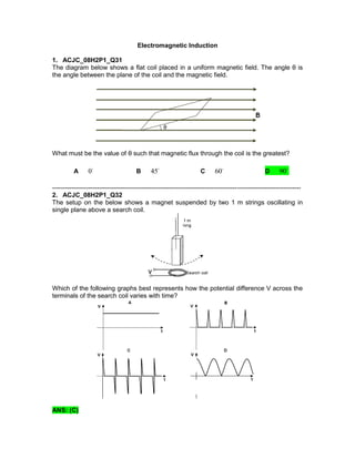
1. Electromagnetic Induction
1. ACJC_08H2P1_Q31
The diagram below shows a flat coil placed in a uniform magnetic field. The angle θ is
the angle between the plane of the coil and the magnetic field.
What must be the value of θ such that magnetic flux through the coil is the greatest?
A 0 B 45 C 60 D 90
---------------------------------------------------------------------------------------------------------------------
2. ACJC_08H2P1_Q32
The setup on the below shows a magnet suspended by two 1 m strings oscillating in
single plane above a search coil.
Which of the following graphs best represents how the potential difference V across the
terminals of the search coil varies with time?
ANS: (C)
2. 3. ACJC_Physics Prelim_H2P1_Q29
The diagram below shows a wire conductor, RS, positioned perpendicular to a uniform
magnetic field directed into the paper.
What is the direction in which the wire could be moved at a constant speed to produce
the maximum potential difference across its ends, R and S?
A perpendicular to only the magnetic field
B perpendicular to only the length of the wire
C perpendicular to both the length of the wire and the magnetic field
D in the direction 45° to the length of the wire
---------------------------------------------------------------------------------------------------------------------
4. ACJC_Physics Prelim_H2P1_Q31
A metal rod is moved across a magnetic field as shown in the diagram below. Which one
of the factors would not affect the value of the induced e.m.f. across the rod?
A The length of the rod
B The thickness of the rod
C The magnetic flux density of the field
D The speed with which the rod moves across the magnetic field
---------------------------------------------------------------------------------------------------------------------
3. 5. ACJC_Physics Prelim_H2P1_Q32
When a small cylindrical magnet is released from rest at the top of a copper pipe, the
magnet falls very slowly through the pipe.
Which of the following does not help to slow down the motion of the magnet as it falls
through the same length of the pipe?
A Use a pipe with a thinner layer
B Use a pipe of material with lower resistivity
C Use a stronger magnet of the same mass
D Use a lighter magnet
------------------------------------------------------------------------------------------------------------
6. CJC_2008 Physics Prelim_H2P1_Q32
A straight, horizontal, current-carrying wire lies at right angles to a horizontal magnetic
field. The field exerts a vertical force of 8.0 mN on the wire.
The wire is rotated, in its horizontal plane, through 30° as shown. The flux density of the
magnetic field is halved.
What is the vertical force on the wire?
A 2.0 mN B 3.5 mN C 4.6 mN D 8.0 mN
4. Reason:
---------------------------------------------------------------------------------------------------------------------
7. IJC_2008 Physics Prelim_H2P1_Q30
A 50-loop circular coil has a radius of 3.0 cm. It is oriented such that the field lines of a
magnetic field are normal to the area of the coil. The magnetic field strength is increased
steadily from 0.10 T to 0.35 T in a time of 2.0 s. Find the average induced e.m.f in the
coil.
A 4
3.5 10 V
B 2
1.8 10 V
C 3.5 V
D 2
1.8 10 V
Reason:
---------------------------------------------------------------------------------------------------------------------
8. IJC_2008 Physics Prelim_H2P1_Q31
In the electromagnetic brake as shown below, which of the following forces is eventually
responsible in causing the vehicle to slow down?
5. A Electromotive force produced in the metal disc
B Frictional force due to the contact of the axle and the metal disc
C Centripetal force acting on the current-carrying metal disc
D Magnetic force acting on the current-carrying metal disc
Reason:
The working principle of an electromagnet is as follows:
A metal disc driven by the axle of the wheels is positioned between the poles of an
electromagnet. When the brake is stepped, the electromagnet is switched on.
Subsequently, the rotation of the disc in the magnetic field causes an e.m.f. to be
induced between the rim and the centre of the disc. Currents are, in turn, induced. A
magnetic force will act on the current-carrying disc to oppose its motion and hence
cause the vehicle to slow down.
---------------------------------------------------------------------------------------------------------------------
9. JJC_2008 Physics Prelim_H2P1_Q30
A single circular loop of wire is placed in a uniform magnetic field of 1.2 T that is normal
to the plane of the loop. The area of the loop varies with respect to time as shown in the
figure below. What is the e.m.f. induced?
A -3
1.2 10 V
B -3
2.4 10 V
C -3
3.6 10 V
D -3
7.2 10 V
6. Reason:
---------------------------------------------------------------------------------------------------------------------
10. JJC_2008 Physics Prelim_H2P1_Q31
Which of the following statements best describes the motion of the suspended ring
immediately after the switch is closed as shown in the figure below?
A The ring remains motionless.
B The ring is repelled.
C The ring is attracted towards the solenoid.
D The ring oscillates towards and away from the solenoid.
Reason:
When switch closes, the solenoid becomes a magnet. By Lenz’s Law, a current will be
induced in the aluminum ring such that its effect is to oppose the effect of the ‘sudden
appearance’ of a magnet, hence the ring is repelled immediately after the switch is
closed.
---------------------------------------------------------------------------------------------------------------------
7. 11. PJC_2008 Physics Prelim_H2P1_Q28
A straight wire AB is moved across a magnetic field causing a current to be induced in
the direction shown in the diagram.
Which direction did the wire move?
A to the left B to the right C into the plane D out of the plane
Reason:
By Fleming right hand rule, the wire must be moving out of the plane to induce a current
as shown in the Fig.
---------------------------------------------------------------------------------------------------------------------
12. PJC_2008 Physics Prelim_H2P1_Q29
A sinusoidal magnetic field, B, is applied perpendicular to the plane of a small flat coil of
copper wire. The equation for the changing flux density is given by 0
2
sinB B
T
,
where 0B is the amplitude and T, the period of the sinusoidal magnetic field. At which
time, t, is the magnitude of the e.m.f. induced in the coil a maximum?
A T/8 B T/4 C 3T/8 D T/2
Reason:
---------------------------------------------------------------------------------------------------------------------
8. 13. RJC_2008 Physics Prelim_H2P1_Q31
Two vertical loops A and B, parallel to each other are centred on the same horizontal
line, perpendicular to both the vertical planes of A and B as shown in the figure below.
Loop A is fixed and loop B is free to move. Initially, switch S is closed. Just after switch S
is opened, loop B will
A move upward
B move downward
C be repelled by loop A
D be attracted to loop A
---------------------------------------------------------------------------------------------------------------------
14. SAJC_2008 Physics Prelim_H2P1_Q29
A bar magnet is held above the centre of a wire loop in a horizontal plane as shown in
the figure below.
The magnet is then dropped with the south end directed toward the loop. Which of the
following shows the correct directions for the current induced while the magnet is falling
toward the loop and after the magnet has passed through the loop and moves away
from it?
9. ---------------------------------------------------------------------------------------------------------------------
15. SAJC_2008 Physics Prelim_H2P1_Q30
Which of the following statements best describes the motion of the suspended ring as
shown in the figure below when a large alternating current is passed through the
solenoid?
A The ring remains stationary.
B The ring will be attracted towards the solenoid.
C The ring rotates about the axis of the thread suspending it.
D The ring moves back and forth from the solenoid.
---------------------------------------------------------------------------------------------------------------------
16. YJC_2008 Physics Prelim_H2P1_Q28
Two parallel rails with negligible resistance are 10.0 cm apart and are connected
by a 5.00 W resistor. The circuit also contains a metal rod of resistance 15.0 W
sliding at a constant speed of 2.00 m s−1 along the rails as shown below.
A uniform magnetic field B of flux density 10.0 mT is applied perpendicularly to the plane
of the rails. Determine the current in the 5.00 W resistor.
Magnet falling toward loop Magnet moves away from loop
A Clockwise Clockwise
B Clockwise Anti-clockwise
C Anti-clockwise Anti-clockwise
D Anti-clockwise Clockwise
10. A 0.100 A C 4
1.33 10 A
B 4
4.00 10 A
D 4
1.00 10 A
---------------------------------------------------------------------------------------------------------------------
17. YJC_2008 Physics Prelim_H2P1_Q29
A bar magnet is dropped from rest vertically into a solenoid connected to a
sensitive voltage sensor. The entire body of the magnet spent a time of 2t
inside the solenoid.
Which of the following graphs best represents the time variation of the voltage, V
recorded by the sensor?
ANS: (D)
---------------------------------------------------------------------------------------------------------------------
11. 18. SRJC_2008 Physics Prelim_H2P1_Q31
ABCD is a wire frame in the shape of an isosceles trapezium (i.e. length AB = length
CD), enters a magnetic field with flux density B at t = 0 as shown in the figure below.
If the total resistance of the wire frame is R, what is the value of the induced current in
the wire frame after time t seconds, assuming that the frame has not entered the field
completely by then?
A 0
B
2 sin
Bv
vt l
R
C
2
tan
Bv vt
l
R
D B v
Reason:
---------------------------------------------------------------------------------------------------------------------
12. 19. SRJC_2008 Physics Prelim_H2P1_Q32
A plane circular coil of 30 turns, each of diameter 1.0 cm, rotates 1800 times each
minute about a diameter which is perpendicular to a uniform magnetic field of flux
density 4.0 × 10⁻⁵ T. What is the maximum instantaneous value of the induced
electromotive force?
A 0.0 V
B 6
2.8 10 V
C 5
1.8 10 V
D 5
2.3 10 V
Reasoning:
---------------------------------------------------------------------------------------------------------------------
20. MJC_2008 Physics Prelim_H2P1_Q31
A rectangular coil moves in the direction parallel to a long straight current carrying
conductor as shown below.
The conductor carries a steady direct current. Which of the following statements is true?
A There is no induced current in the coil.
B The induced current flows clockwise in the coil.
C
The magnitude of the induced current is proportional to
1
2
.
D
The magnitude of the induced current in the coil varies with the speed at which the
coil is moving.
13. Reasoning:
The change of magnetic flux linkage is a constant. Hence induced emf is zero.
---------------------------------------------------------------------------------------------------------------------
21. MJC_2008 Physics Prelim_H2P1_Q32
A breathing monitoring device consists of a coil of 80 turns wrapped around a patient’s
chest. As the patient inhales, the area of the coil is observed to increase from 0.120 m2
to 0.124 m2. The Earth’s magnetic flux density is 50 μT and makes an angle of 22.5°
with the axis of the coil.
If the patient inhales in a time interval of 1.59 s, what is the average e.m.f. induced in the
coil during the inhalation?
A 3.9 μV B 9.3 μV C 10.1 μV D 22 μV
Reasoning:
------------------------------------------------------------------------------------------------------------
22. DHS_2008 Physics Prelim_H2P1_Q31
Krystal pushes a short bar of magnet at a constant speed through a long solenoid. A
galvanometer is connected across the solenoid.
14. Which graph best represents the variation of the galvanometer deflection θ with time t?
ANS (A)
Assume: Strength of the magnet is strong such that its strength does not vary much over
short distances, magnet starts near solenoid at a constant speed.
Before magnet enters solenoid, it approaches the solenoid at a constant speed. Rate of
change of magnetic flux linking the solenoid is thus constant. Induced e.m.f and hence
induced current is constant. Induced current will flow in an anticlockwise manner (for an
observer looking from the side i.e. looking at the cross section of the solenoid).
As magnet enters the solenoid, induced current will flow in an anticlockwise direction
(cross sectional view) in the part of the solenoid in front of the N pole of the magnet
Induced current will flow in a clockwise manner (cross sectional view) in part of the
solenoid behind the S pole of the magnet.
The net current flows in an anticlockwise direction (cross sectional view) as the magnet
moves towards the centre but decreases as it does so.
The net current flow will be zero when the magnet is at the centre of the solenoid.
The net current flows in a clockwise direction (cross sectional view) as it moves away
from the centre of the solenoid and increases as it does so.
As magnet leaves solenoid at constant speed, induced current is constant and flows in
clockwise direction (cross sectional view).
(if we don’t assume the strength of the magnet is constant over short distances (which
suggests option A, why should the graph be linear in the first place?)
------------------------------------------------------------------------------------------------------------
15. 23. DHS_2008 Physics Prelim_H2P1_Q32
A square coil is placed in a region of uniform magnetic field as shown below. Soke May
then moves the coil from A to B.
Which of the following statements correctly describe the e.m.f. induced in the coil?
A
There is no e.m.f. induced because the total magnetic flux linking the circuit
is the same.
B
There is no e.m.f. induced because the velocity of the coil is perpendicular to
the magnetic field
C
E.m.f. is induced in the coil and it is proportional to the rate of change of
displacement of the coil
D
E.m.f. is induced in the coil and it is inversely proportional to the rate of
change of displacement of the coil
---------------------------------------------------------------------------------------------------------------------
24. NJC_2008 Physics Prelim_H2P1_Q31
In the above figure, a copper disc rotates uniformly between the pole-pieces of a
powerful magnet (not shown in figure) in a clockwise direction. P and Q are metallic
brushes making contact with the axle and the edge of the disc respectively. Which of the
following statements is correct?
16. A No current flows through R because there is no flux change through the disc.
B No current flows through R because P and Q are at the same horizontal level.
C A steady current flows from P, through R, to Q.
D A steady current flows from Q, through R, to P.
---------------------------------------------------------------------------------------------------------------------
25. NYJC_2008 Physics Prelim_H2P1_Q32
The diagram shows a magnet standing on the bottom of a dish filled with a conducting
solution. A copper wire is suspended freely from a point above the magnet with its tip in
the conducting solution. It is held in the position shown
The switch is closed and the wire released.Which of the following will be observed?
A The wire will rotate about the magnet.
B The wire will be attracted to the magnet.
C The magnet will rotate about its vertical axis.
D The solution in the dish will rotate about the magnet.
No answer provided. The electrons passing through the solution (between the two wires
will experience a force into the page (assuming magnetic field at that point to be
downwards) but does that mean that the solution will rotate?
Also, current within the solution could be carried by both positive ions and negative ions
(not too sure about this). The forces acting on positive and negative ions are opposite,
will there still be a net flow of the solution?
Electrons flowing in the top part of the tilted wire will experience a force out of the page
(Assuming magnetic field to be pointing up) while electrons in the bottom part of the wire
will experience a force into the page (assuming magnetic field at that point to be pointing
down) so does that mean the titled wire will bend out of the page but diagram is 2D or
3D?
Question seems ambiguous from my point of view.
---------------------------------------------------------------------------------------------------------------------
17. 26. NYJC_2008 Physics Prelim_H2P1_Q23
A square loop of wire, in a uniform magnetic field, is rotating at a constant rate about an
axis as shown. The magnetic field is directed out of the plane of the page. At time t = 0
the plane of the loop is perpendicular to the magnetic field and side XY is moving out of
the page.
Which graph best represents the variation of the magnetic flux through the loop
with time?
ANS: (C)
---------------------------------------------------------------------------------------------------------------------
X
Y
A B
C D
18. 27. VJC_2008 Physics Prelim_H2P1_Q30
A closed wire loop in the form of a square of area is mounted with its plane horizontal.
The loop has a resistance of 3
2.0 10
. The loop is situated in a magnetic field of
strength 0.70 T directed vertically downwards. When the field is switched off, it
decreases to zero at a uniform rate in 0.80 s.
What is the energy dissipated in the loop during the change in magnetic field.?
A 4
3.9 10 J
B 4
7.8 10 J
C 4
9.8 10 J
D 4
16 10 J
---------------------------------------------------------------------------------------------------------------------
28. TJC_2008 Physics Prelim_H2P2_Q3b
A glass U-tube containing liquid sodium is constructed from a hollow tubing having a
square cross-section as shown in the figure below.
Electrodes are set into the upper and lower faces of the horizontal section and a current
I is passed through the electrodes. A uniform horizontal magnetic field is applied at right
angles to the axis of the horizontal section of the tube. A magnetic force is then exerted
on the liquid due to the magnetic field.
This technique has been used as a means of pumping liquids. Explain why the energy
required to maintain the current is larger when the liquid is in motion than when
stationary.
19. Solution:
When the liquid is in motion, it cuts the magnetic field. By Faraday’s law an emf is
induced.
By Lenz’s law, an induced current will flow to oppose the motion of the liquid.
Also, the liquid experiences drag when in motion. Hence more energy is required to
maintain the current when liquid is in motion
[1]
[1]
[1]
---------------------------------------------------------------------------------------------------------------------
29. TJC_2008 Physics Prelim_H2P2_Q5
(a) A bar magnet with its axis along a coil axis, is released from rest at a position above
the fixed coil so that it drops through the coil as shown in Fig. 5.1. The terminals of
the coil are connected to a data logger which records the induced e.m.f. at regular
intervals. The variation of the induced e.m.f. with time is shown in Fig. 5.2.
Explain, using the laws of electromagnetic induction, why
(i) two momentary deflections in opposite directions are observed, [2]
(ii) the second momentary deflection is larger than the first. [2]
(b) In Fig.5.3, the magnetic field has a uniform flux density of 4
2.0 10 T
and is
directed out the paper. A wire coil placed at P is in the plane of the paper and away
from the field. The coil has 200 turns, a total resistance of 2.0 Ω and an area of 10
cm2. The coil is moved from P to R in 0.20 s.
20. (i) Calculate the charge which flows in the coil. [2]
(ii) Discuss whether there would be any effect on the charge flow for each of the
following changes:
(a) Increasing the number of turns in the coil. [1]
(b) Increasing the time to move it. [1]
Solution:
5 (a) (i) When the magnet is dropped above the coil, there is an increase in flux
linkage with the coil. When the magnet is dropped below the coil, there is
a decrease in flux linkage with the coil.
According to Lenz’s law, the direction of the induced emf is such as to
oppose the change in flux linkage, hence the deflections are in opposite
directions.
[1]
[1]
(ii) At a position below the coil, there is an increase in the speed of the
magnet. Hence the rate of change of magnetic flux linkage increases.
According to Faraday’s law, the magnitude of the induced emf is
proportional to the rate of change of magnetic flux linkage. Hence the
second deflection is larger than the first.
[1]
[1]
(b) (i) Q = (NBA – 0) /R = (200 x 2.0 x 10-4
x 10 x 10-4
) / 2.0
= 2.0 x 10⁻⁵
C
[1]
[1]
(ii) 1. There would be no change since increasing the number of turns would
increase the resistance of the coil by the same amount.
2. There is also no change in the charge flowing since charge flowing is
independent of time.
[1]
[1]
---------------------------------------------------------------------------------------------------------------------
21. 30. SAJC_2008 Physics Prelim_H2P2_Q5
(a) State the laws of electromagnetic induction.
(b) The magnetic field shown in Fig. 5.1 below has a uniform magnitude of 25.0 mT
directed into the paper. The initial diameter of the loop is 2.00 cm.
(i) The wire is quickly pulled taut, and the loop shrinks to a diameter of zero in 50.0
ms.
1. Determine the average voltage induced between endpoints A and B.
[2]
2. State and explain whether the potential at A is higher or lower than the
potential at B. [3]
(ii) Suppose the loop is undisturbed, but the magnetic field increases to 100 mT in
4.00 × 10⁻³ s. Determine the average voltage across terminals A and B during
this period. [2]
22. Solution
(a) Faraday’s law states that an induced electromotive force is directly proportional to
the rate of change of magnetic flux linkage. [ 1 ]
Lenz’s law states that the direction of the induced electromotive force is such that its
effects oppose the change which causes it. [ 1 ]
(b) (i) 1
(b) (i) 2
According to Lenz’s law, as the loop shrinks, the direction of the induced EMF is such
that it will cause an induced current to flow in a direction such that it opposes the
shrinking of the loop. Hence it causes an outward radial force on the loop [ 1 ]. Hence,
by Fleming’s left hand rule, induced current will flow from A to B [ 1 ] and hence A has a
lower potential than B. [ 1 ]