Downloaded 48 times


![RAGHU ENGINERING COLLEGE BATCH 8 EM-1 18
•[1] Ilie F., Bulucea C.A., Popescu M.C.,
Simulations of Oil-filled Transformer Loss-
of-Life Models, Proceedings of the 11th
International Conference on Mathematical
Methods and Computational Techniques in
Electrical Engineering,
•Electrical Machines notes
Reference](https://image.slidesharecdn.com/electricalengineering1-190902133918/85/ELECTRICAL-MACHINES-1-18-320.jpg)


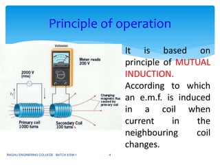
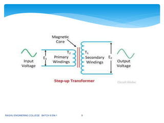
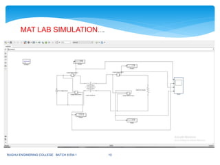
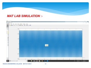
1. The document discusses a case study on simulating a step-up transformer in MATLAB. 2. A step-up transformer increases voltage by having more turns in the secondary coil than the primary coil, inducing a higher voltage on the secondary side. 3. The case study involves simulating a step-up transformer in MATLAB, obtaining the simulation results, and analyzing the technical specifications and applications of step-up transformers.