
Recommended
More Related Content
What's hot
What's hot (20)
Similar to DC GENERATOR EE8301 Electrical Machines 1
Similar to DC GENERATOR EE8301 Electrical Machines 1 (20)
Recently uploaded
Recently uploaded (20)
DC GENERATOR EE8301 Electrical Machines 1
- 1. UNIT : 4 DC GENERATOR INSTITUTE OF ROAD AND TRANSPORT TECHNOLOGY ELECTRICAL AND ELECTRONICS ENGINEERING EE8301 Electrical Machines 1
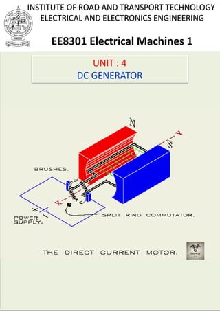
- 2. D.C GENERATORS U1.1 Generator principle An electrical generator is a machine which converts mechanical energy (or power) into electrical energy (or power). Induced e.m.f is produced in it according to Faraday's law of electromagnetic induction. This e.m.f cause a current to flow if the conductor circuit is closed. Hence, two basic essential parts of an electrical generator are: a) Magnetic field. b) Conductor or conductors which can move as to cut the flux. Generators are driven by a source of mechanical power, which is usually called the prime mover of the generator(steam turbine, diesel engine, or even an electric motor). U1.2 Simple loop generator In fig.(1.1) is shown a single turn rectangular copper coil ( AABB ) rotating about its own axis in a magnetic field provided by either permanent magnets or electromagnets. The two end of the coil are joined to two slip-rings which are insulated from each other and from the central shaft. Two collecting brushes (carbon or copper) press against the slip- rings. The rotating coil may be called (armature) and the magnets as (field magnets). One way to generate an AC voltage is to rotate a coil of wire at constant angular velocity in a fixed magnetic field, fig. (1.1). (slip rings and brushes connect the coil to the load). The magnitude of the resulting voltage is proportional to the rate at which flux lines are cut (faraday's law), and its polarity is dependent on the direction the coil sides move through the field. INSTITUTE OF ROAD AND TRANSPORT TECHNOLOGY ELECTRICAL AND ELECTRONICS ENGINEERING EE8301 Electrical Machines 1 DC GENERATOR - PRINCIPLE OF OPERATION 1
- 3. The direction of an induced e.m.f can be predetermined by using Flemings URight-handU rule (often called the geneURatorU rule) fig.(1.2). FU Uirst finger- UFieldU ThuMU Ub – UMUotion sEU cU ond finger – UEU.m.f Since the rate of cutting flux varies with time, the resulting voltage will also vary with time. For example in (a), since the coil sides are moving parallel to the field, no flux lines are being cut and the induced voltage at this instant (and hence the current) is zero. (this is defined as the 0P P position of the coil). As the coil rotates from the 0P P position, coil sides AAP P and BBP P cut across flux lines, hence, voltage builds, reaching a peak when flux is cut at the maximum rate in the 90P P position as in (b). Note the polarity of the voltage and the direction of current. As the coil rotates further, voltage decrease, reaching zero at the 180P Pposition when the coil sides again move parallel to the field as in (c). At this point, the coil has gone through a half-revolution. During the second half-revolution, coil sides cut flux in directions opposite to that which they did in the first half revolution, hence, the polarity of the induced voltage reverses. As indicated in (d), voltage reaches a peak at the 270P P point, and, since the polarity of the voltage has changed, so has the direction of current. When the coil reaches the 380P P position, voltage is again zero and the cycle starts over. Fig. (1.1) shows one cycle of the resulting waveform. Since the coil rotates continuously, the voltage produced will be a repetitive, periodic waveform as you saw in fig. (1.1). E.m.f. generated in one side of loop= Blv sin , and total e.m.f. generated in loop=2 Blv sin (volts), where (B): flux density in (teslas), ( l ): length in (meters), ( v ): the conductor velocity, is measured in meters per second. INSTITUTE OF ROAD AND TRANSPORT TECHNOLOGY ELECTRICAL AND ELECTRONICS ENGINEERING EE8301 Electrical Machines 1 DC GENERATOR - PRINCIPLE OF OPERATION 2
- 4. Fig.(1.1) Generating an AC voltage. The 0P P position of the coil is defined as in (a) where the coil sides move parallel to the flux lines. INSTITUTE OF ROAD AND TRANSPORT TECHNOLOGY ELECTRICAL AND ELECTRONICS ENGINEERING EE8301 Electrical Machines 1 DC GENERATOR - PRINCIPLE OF OPERATION 3
- 6. U1.3 Construction of DC Generators The parts of a simple DC generator are shown in fig.(1.3). The principle of operation of a DC generator is similar to that of the AC generator, which was discussed previously. A rotating armature coil passes through a magnetic field that develops between the north and south polarities of permanent magnets or electromagnets. As the coil rotates, electromagnetic induction causes current to be induced into the coil. The current produced is an alternating current. However, it is possible to convert the alternating current that is induced into the armature into a form of direct current. This conversion of AC into DC is accomplished through the use of a commutator. The conductors of the armature of a DC generator are connected to commutator segments. The commutator shown in fig. (1.3) has two segments, which are insulated from one an other and from the shaft of the machine on which it rotates. An end of each armature conductor is connected to each commutator segment. The purpose of the commutator is to reverse the armature coil connection to the external load circuit at the same time that the current induced in the armature coil reverses. This causes DC at the correct polarity to be applied to the load at all times. Figure (1.2) Fleming's Right-hand rule. INSTITUTE OF ROAD AND TRANSPORT TECHNOLOGY ELECTRICAL AND ELECTRONICS ENGINEERING EE8301 Electrical Machines 1 DC GENERATOR - CONSTRUCTION AND COMPONENTS 4
- 8. Fig. (1.3) Simple drawing of the basic parts of DC generator Fig.(1.4) Output waveforms of a DC generator. (A) Pulsating DC developed by simple single-coil generator. (B) Pure DC developed by a more complex generator using many turns of wire and many commutator segments. INSTITUTE OF ROAD AND TRANSPORT TECHNOLOGY ELECTRICAL AND ELECTRONICS ENGINEERING EE8301 Electrical Machines 1 DC GENERATOR - CONSTRUCTION AND COMPONENTS 5
- 10. U1.4 Armature Windings Armature windings can be divided into two groups, depending on how the wires are joined to the commutator. These are called (lap windings) and (wave windings). These windings will be examined individually below, and their advantage and disadvantage will be discussed. U1.4.1 The Lap WindingU The simplest type of winding construction used in modern DC machines is the simplex lap winding. A simplex lap winding is a rotor (armature) winding consisting of coils containing one or more turns of wire with the two end of each coil coming out at adjacent commutator segments fig. (1.5). The number of current paths in a machine is : a mp lap winging, Where: a : number of current path in the rotor. m : plex of the windings (1,2,3,etc….) p : number of poles on the machines. Lap wound generators produce high current, low voltage output. Fig. (1.5) Lap-wound DC machine. INSTITUTE OF ROAD AND TRANSPORT TECHNOLOGY ELECTRICAL AND ELECTRONICS ENGINEERING EE8301 Electrical Machines 1 DC GENERATOR - LAP AND WAVE WINDINGS 6
- 11. U1.4.2 The Wave WindingU The wave winding is an alternative way to connect the rotor (armature) coils to the commutator segments. Fig. (1.6) shows a simple wave winding. In this simplex wave winding, every other rotor coil connects back to a commutator segment adjacent to the beginning of the first coil. Therefore, there are two coils in series between the adjacent commutator segments. Furthermore, since each pair of coils between adjacent segments has a side under each pole face, all output voltage are the sum of the effects of every pole, and there can be no voltage imbalances. wave windings, generators produce higher-voltage, low current outputs, since the number of coils in series between commutator segments permits a high voltage to be built up more easy than with lap windings. a 2m multiplex wave Fig.(1.6) Wave wound DC machine. INSTITUTE OF ROAD AND TRANSPORT TECHNOLOGY ELECTRICAL AND ELECTRONICS ENGINEERING EE8301 Electrical Machines 1 DC GENERATOR - LAP AND WAVE WINDINGS 7
- 12. U1.5 Electromotive Force(e.m.f) Equation The induced voltage in any given machine depends on three factor: 1. The flux in the machine 2. The speed of the machine's rotor. 3. A constant depending on the construction of the machine. The voltage out of the armature of a real machine is equal to the number of conductors per current path time the voltage on each conductor. The voltage in any single conductor under the pole faces was previously shown to be. ein Blv Where B , the flux density, is measured in teslas, l , the length of conductor in the magnetic field, is measured in meters, and conductor velocity, is measured in meters per second. The voltage out of the armature of a real machine is thus v , the ZBlv a Where ( z ) is the total number of conductors and (a) is the number EA of current paths. The velocity of each conductor in rotor can be expressed v r , where r is the radius of the rotor, , angular velocity in radians per second, so ZBlr a This voltage can be re-expressed in a more convenient form by EA noting that the flux of a pole is equal to the flux density under the pole times the pole's area: BAp The rotor of the machine is shaped like a cylinder, so its area is A 2rl INSTITUTE OF ROAD AND TRANSPORT TECHNOLOGY ELECTRICAL AND ELECTRONICS ENGINEERING EE8301 Electrical Machines 1 DC GENERATOR - EMF EQUATIONS 8
- 13. If there are P poles on the machine, then the portion of the area associated with each pole is the total area A divided by the number of poles P: P P A 2rl AP The total flux per pole in the machine is thus P P B(2rl) 2rlB P BA Therefore, the internal generated voltage in the machine can be expressed as : Finally, Where In modern industrial practice, it is common to express the speed of a machine in revolutions per minute instead of radians per second. The conversion from revolutions per minute to radians per second is. 2 .n 60 So the voltage equation with speed expressed in terms of revolutions per minute is Where EA K.. ZP 2.a K EA K..n K ZP 60.a INSTITUTE OF ROAD AND TRANSPORT TECHNOLOGY ELECTRICAL AND ELECTRONICS ENGINEERING EE8301 Electrical Machines 1 DC GENERATOR - EMF EQUATIONS 9
- 14. U1.6 Types of D.C Generators:U D.C Generators are classified according to the way in which a magnetic field is developed in the stator of the machine. Thus, there are three basic classification DC generators (1) permanent-magnet field (2) separately-excited field and (3) self-excited field. 1) permanent-magnet field permanent-magnet DC machines are widely found in a wide variety of low-power applications. The field winding is replaced by a permanent magnet, resulting in simpler construction. Chief among these is that they do not require external excitation and its associated power dissipation to create magnetic fields in the machine the space required for the permanent magnets may be less than that required for the field winding, and thus machine may be smaller, and in some cases cheaper, than their externally excited counter parts. Notice that the rotor of this machines consists of a conventional DC armature with commutator segments and brushes. Fig. (1.7) Cross section of a typical permanent-magnet machines. INSTITUTE OF ROAD AND TRANSPORT TECHNOLOGY ELECTRICAL AND ELECTRONICS ENGINEERING EE8301 Electrical Machines 1 DC GENERATOR - METHODS OF EXCITATION 10
- 15. 2) Separately-excited field Separately-excited generators are those whose field magnets are energized from an independent external source of DC current. It is shown diagrammatically in fig (1.8). Fig. (1.8) Simplified illustration of a separately DC generator. INSTITUTE OF ROAD AND TRANSPORT TECHNOLOGY ELECTRICAL AND ELECTRONICS ENGINEERING EE8301 Electrical Machines 1 DC GENERATOR - METHODS OF EXCITATION 11
- 16. 3) Self-excited field Self-excited generators are those whose field magnets are energized by the current produced by the generators themselves. Due toresidual magnetism, there is always present some flux in poles. When the armature is rotated, some e.m.f and hence some induced current is produced which is partly or fully passed through the field coils thereby strengthening the residual pole flux. There are three types of self-excited generators named according to the manner in which their field coils ( or windings) are connected to armature. (a) Shunt -Wound The field windings are connected across or in parallel with the armature conductors and have the full voltage of the generator applied across them fig. (1.9). Fig. (1.9) Simplified illustration of a self-excited, shunt wound DC generator. INSTITUTE OF ROAD AND TRANSPORT TECHNOLOGY ELECTRICAL AND ELECTRONICS ENGINEERING EE8301 Electrical Machines 1 DC GENERATOR - METHODS OF EXCITATION 12
- 17. (b) Series -Wound In this case, the field windings are joined in series with the armature conductors fig. (1.10). As they carry full load current, they consist of relatively few turn of thick wire or strips. Such generators are rarely used except for special purposes. Fig. (1.10) Simplified illustration of a self-excited, series-wound DC generator. INSTITUTE OF ROAD AND TRANSPORT TECHNOLOGY ELECTRICAL AND ELECTRONICS ENGINEERING EE8301 Electrical Machines 1 DC GENERATOR - METHODS OF EXCITATION 13
- 18. (c) Compound–Wound The compound-wound D.C generator has two sets of field windings. One set is made of low-resistance windings and is connected in series with the armature circuit. The other set is made of high-resistance wire and is connected in parallel with the armature circuit. A compound- wound D.C generator is illustrated in figure (1.11), can be either short- shunt or long-shunt. In a compound generator, the shunt field is stronger than the series field. When series field aids the shunt field, generator is said to be cumulatively-compounded. On the other hand if series field opposes the shunt field, the generator is said to be differentially compounded. Various types of DC generators have been shown separately in fig. (1.12). Fig. (1.11) Simplified illustration of a compound- wound DC generator. INSTITUTE OF ROAD AND TRANSPORT TECHNOLOGY ELECTRICAL AND ELECTRONICS ENGINEERING EE8301 Electrical Machines 1 DC GENERATOR - METHODS OF EXCITATION 14
- 19. Fig. (1.12) Types of D C Generators. EU xample (1.1):U A four-pole generator, having lap-wound armature winding has 51 slot, each slot containing 20 conductors. What will be the voltage generated in the machine when driven at 1500 r.p.m assuming the flux per pole to be 7 mWb.? SU olution DC Generators permanent-magnet Separately-excited fieldSelf-excited field Series- Wound Shunt- Wound Compound -Wound Long- Shunt Short- Shunt Cumulative Differential INSTITUTE OF ROAD AND TRANSPORT TECHNOLOGY ELECTRICAL AND ELECTRONICS ENGINEERING EE8301 Electrical Machines 1 DC GENERATOR - METHODS OF EXCITATION 15
- 23. U1.7 Armature Reaction An armature reaction is meant the effect of magnetic field set up by armature current on the distribution of flux under main poles of a generator. The armature magnetic field has two effects: (a) it demagnetizes or weakens the main flux. (b) it cross-magnetizes or distorts it. The first effect leads to reduced generator voltage and the second to the sparking at the brushes. These effects are well illustrated in fig(1.13) which shows the flux distribution of a bipolar generator when there is no current in the armature conductors. Magnetic neutral axis (M.N.A) may be defined as the axis along which no (e.m.f) is produced in the armature conductors because they then move parallel to the lines of flux or (M.N.A) is the axis which is perpendicular to the flux passing through the armature, brushes are always placed along (M.N.A). In general, the magnetic neutral axis shifts in the direction of motion for a generator and opposite to the direction of motion for motor. Furthermore, the amount of the shift depends on the amount of rotor current and hence on the load of machine. Fig.(1.13) G.N.AM.N.A INSTITUTE OF ROAD AND TRANSPORT TECHNOLOGY ELECTRICAL AND ELECTRONICS ENGINEERING EE8301 Electrical Machines 1 DC GENERATOR - ARMATURE REATION 16
- 24. U1.8 Compensating Windings These are used for large direct current machines. Their function is to neutralize the cross-magnetizing effect of armature reaction. The compensating windings are embedded in slots in poles shoes and are connected in series with armature in such away that the current in them flows in opposite direction to that flowing in armature conductors directly below with pole shoes. An elementary scheme of compensating winding is shown in fig.(1.14) Ampere-turns of compensating winding are equal and opposite to those due to armature conductors that are opposite the pole face. Compensating Winding B A C Compensating Winding Interpole constructed on a few turns of heavy gage wire. Carries load current. Produces cancelling mmf so flux distortion is minimized. INSTITUTE OF ROAD AND TRANSPORT TECHNOLOGY ELECTRICAL AND ELECTRONICS ENGINEERING EE8301 Electrical Machines 1 DC GENERATOR - ARMATURE REATION 17
- 25. U1.9 Characteristics of a D.C Generators Following are the three most important characteristics of curves of a DC generator: 1. No-load saturation characteristic (ER oR/IR fR) It is also known as magnetic (c/s) or open-circuit characteristic (O.C.C). It shows the relation between the no-load generated e.m.f in armature ER oR, and the field or exciting current (IR fR) at a given fixed speed. It is just the magnetization curve for the material of the electromagnets. Its shape is practically the same for all generators whether separately-excited or self-excited. 2. Internal Characteristic (E/IR aR) It gives the relation between the e.m.f, E actually induced in the armature and the armature current (IR aR). This (c/s) is of interest mainly to the designer. 3. External Characteristic (VR LR/IR LR) It is also referred to as performance (c/s) or sometime voltage- regulation curve. It gives relation between the terminal voltage (VR LR) and the load current (IR LR). This curve lies below the internal (c/s) between it takes into account the voltage drop over the armature circuit resistance. The values of (VR LR) are obtain by subtracting (IR aR RR aR) from corresponding values of (E). This (c/s) is of great importance in judging the suitability of a generator for a particular purpose. INSTITUTE OF ROAD AND TRANSPORT TECHNOLOGY ELECTRICAL AND ELECTRONICS ENGINEERING EE8301 Electrical Machines 1 DC GENERATOR - CHARACTERISTICS OF DC GENERATOR 18
- 26. Fig.(1.15) It can be varied (IR fR) from zero upwards by a rheostat and its value read by an ammeter (A) connected in the field circuit as shown. Now, the voltage equation of a D.C generator is: volt Hence, if the speed is constant, the above relation becomes: It is obvious that when (IR fR) is increased from its initial small value, the flux () and hence generated e.m.f, ER oR increase directly as current while the poles are unsaturated. This is represented by straight portion (o d) in fig.(1.15). But as the flux density increases, the poles become saturated, so a greater increase in (IR fR) is required to produce a given increase in voltage than on the lower part of curve. That is why the upper portion (d b) of curve (o d b) bends over as shown. Field current Eo(Volts) O a b C d A If U1.10 Separately- Excited Generator a) Open-circuit characteristics (ER oR/IR fR) The arrangement for obtaining the necessary data to plot this curve is shown in fig. (1.15) . The exciting or field current (IR fR) is obtained from an external independent D.C source. rheostat Const. o INSTITUTE OF ROAD AND TRANSPORT TECHNOLOGY ELECTRICAL AND ELECTRONICS ENGINEERING EE8301 Electrical Machines 1 DC GENERATOR - CHARACTERISTICS OF DC GENERATOR 19
- 27. (b) Internal and External Characteristic Let us consider a separately-excited generator giving its rated no- load voltage of (ER oR) for a certain constant field current. If there were no armature reaction and armature voltage drop, then this voltage would have remained constant as shown in fig.(1.16) by the dotted horizontal line (I). But when the generator is loaded, the voltage falls due to these two causes, thereby giving slightly drooping (c/s). If we subtract from (ER oR) the values of voltage drops due to armature reaction for different loads. Then we get the value of (E) the e.m.f actually induced in the armature under load conditions. Curve (II) is plotted in this way and is know as the internal characteristic. The straight line (o a) represents the (IR aR RR aR) drops corresponding to different armature currents. If we subtract from (E) the armature drop (IR aR RR aR) we get terminal voltage (VR LR). Curve (III) represents the external (c/s) and is obtained by subtracting ordinates of line (o a) from those of curve (II). V E I a .Ra Ia Fig(1.16) I II III Eo E V Armature Reaction drop Armature Drop Ia .Ra O a VOLTS Eo INSTITUTE OF ROAD AND TRANSPORT TECHNOLOGY ELECTRICAL AND ELECTRONICS ENGINEERING EE8301 Electrical Machines 1 DC GENERATOR - CHARACTERISTICS OF DC GENERATOR 20
- 28. fig.(1.17) IR fO B A Eo () A If U1.11 Self- Excited Generator a) Open-circuit characteristic or magnetization curve for self-excited generator The (O.C.C) or no-load saturated curves for self-excited generators whether shunt or series-connected, are obtained in a similar way. The field winding of the generator whether (shunt or series wound) is disconnected from the machine and connected to an external source of direct current as shown in fig.(1.17). The field or exciting current (IR fR) is varied rheostatically and its value read on the ammeter (A). The machine is driven at constant speed by the prime mover and the generator e.m.f on No-load is measured by voltmeter connected across the armature. (IR fR) is increased by suitable steps(starting from zero) and the corresponding values of (ER oR) are measured. On plotting the relation between (IR fR) and (ER oR) a curve of the form shown in fig.(1.17) is obtained. Due to residual magnetism in the poles, some e.m.f is generated even when (IR fR=0). Hence, the curve starts a little way up. The straight curvature at the lower end is due to magnetic inertia. It is seen that the first part of the curve is practically straight. Const. o rheostat INSTITUTE OF ROAD AND TRANSPORT TECHNOLOGY ELECTRICAL AND ELECTRONICS ENGINEERING EE8301 Electrical Machines 1 DC GENERATOR - CHARACTERISTICS OF DC GENERATOR 21
- 29. Now, connect the field windings back to the armature and run the machine as Ushunt generator .U A shunt generator will excite only if the poles have some residual magnetism and the resistance of the shunt circuit is less than some critical value, the actual value depending upon the machine and upon the speed at which the armature is driven. Suppose curve in fig. (1.18) to represent the open-circuit characteristic of a shunt generator. With increasing excitation. Then, for a shunt current (IR fR) OA, the e.m.f. is AB and. Fig.(1.18) Corresponding resistance of shunt circuit =Ter min al voltage Shunt current AB tan(BOA) OA = slope of OB The resistance line OB represents smaller resistance to which the machine will build up and represent the maximum voltage AB. If field resistance is increased, then slope of the resistance line increase, and hence the maximum voltage to which the generator will build up at a given speed, decreases. B E Eo(andVt)Volt A R O If (Ampere) D Vt Versus If Eo Versus If ER o INSTITUTE OF ROAD AND TRANSPORT TECHNOLOGY ELECTRICAL AND ELECTRONICS ENGINEERING EE8301 Electrical Machines 1 DC GENERATOR - CHARACTERISTICS OF DC GENERATOR 22
- 30. Fig.(1.19) Since (En) for any fixed excitation, hence E1 n1 E n Or 2 2 2 2 1 n n1 E E As seen, for IR f R=OH, ER 1R=HC The value of new voltage for the same IR fR but at nR 2 n1 E HC n2 HD2 In a similar way, other such points can be found and the new O.C.C at nR 2 Rdraw. H If field resistance increased so much that the resistance line dose not cut the O.C.C at all (like OE) then obviously the machine will fail to excite, there will be no " build up" of the voltage. The value of the resistance represented by the tangent to the curve, is known as critical resistance RR CR for a given speed. UHow to draw O.C.C at Different Speed Suppose we are given the data for (O.C.C) of a generator run at a fixed speed, say, nR 1R. It will be shown that (O.C.C) at any other constant speed nR 2 Rcan be deduced from the (O.C.C) for nR 1R. In fig.(1.19) is shown the (O.C.C) for speed nR 1R. nR 1 C Eo(V) n2 D If (A)O INSTITUTE OF ROAD AND TRANSPORT TECHNOLOGY ELECTRICAL AND ELECTRONICS ENGINEERING EE8301 Electrical Machines 1 DC GENERATOR - CHARACTERISTICS OF DC GENERATOR 23
- 31. (b) External Characteristic of a shunt generator We will now proceed to find its external characteristic (VR LR/IR LR) when loaded. It is found that if after building up, a shunt generator is loaded, then its terminal voltage (VR LR) drops with increase in load current. Such a drop in voltage is undesirable especially when the generator is supplying current for load and power for which purposes it is desirable that (VR LR) should remain practically constant and independent of the load. There are three main reasons for the drop in terminal voltage of a shunt generator when under load. I) Armature resistance drop. II) Armature reaction. III) The drop in terminal voltage due to armature resistance and armature reaction results in a decreased field current (IR fR) which further reduces the induced (e.m.f). The terminal voltage V E I a.Ra , E K The shunt generator is first excited on no-load so that it gives its full open circuit voltage (o a). Then, the load is gradually applied and, at suitable intervals, the terminal voltage(VR LR) (as read by the voltmeter) and the load current (IR LR) ( as read by the ammeter AR 2R) are noted. The field current as recorded by ammeter (AR 1R), is kept constant by a rheostat. By plotting these reading. The external (c/s) of fig.(1.20) is obtained. The portion (a b) is working part of this curve. Over this part, if the load resistance is decreased, load current is increased as usual, although this results in a comparatively small additional drop in voltage. These condition hold good till point (b) is reached. This point is known as break-down point. INSTITUTE OF ROAD AND TRANSPORT TECHNOLOGY ELECTRICAL AND ELECTRONICS ENGINEERING EE8301 Electrical Machines 1 DC GENERATOR - CHARACTERISTICS OF DC GENERATOR 24
- 32. R1 R Fig.(1.20) (c) Internal characteristic of a shunt generator As defined before, internal (c/s) gives the relation between (E) and (IR aR). Now in a shunt generator. I a I f IL and E V I a .Ra , f f R V I Hence, (E/Ia) curve can be obtained from (VR L/RIR LR) curve as shown in fig.(1.21). In this figure, (a b) represents the external (c/s) as discussed above. The field resistance line (O B) is drawn as usual. The horizontal distances from (O Y) line to the line (O B) give the values of field currents for different terminal voltages. If we add these distances horizontally to the external characteristic (a b), then we get the curve for the total armature current i.e. dotted curve (a c). For example, point (d) on (a c) is obtained by making (g d=e f). The armature resistance drop line (O M) is the plotted as usual. AR 1 A2 VL B c d Break-Down b A Load current(IR LR) Terminalvoltage(VR L)R o It is found that beyond this point ( where load is maximum =O B) any effort to increase load current by further decreasing load resistance results in decreased load current like(O A) due to a very rapid decrease in terminal voltage. a INSTITUTE OF ROAD AND TRANSPORT TECHNOLOGY ELECTRICAL AND ELECTRONICS ENGINEERING EE8301 Electrical Machines 1 DC GENERATOR - CHARACTERISTICS OF DC GENERATOR 25
- 33. If brush contact resistance is assumed constant, then armature voltage drop is proportional to the armature current. For any armature current (O K), armature voltage drop (IR aR.RR aR= M K). If we add these drops to the ordinates of curve (a c), we get the internal characteristic. Fig.(1.21) (c) Series Generator The magnetization curve of a series DC generator looks very much like the magnetization curve of any other generator. At no load, however, there is no field current, so (VR LR) is reduced to a small level given by the residual flux in the machine. As the load increases, the field current rises, so (E) rises rapidly. The IR aR.(RR aR+RR fR) drop goes up too, but at first the increase in (E) goes up more rapidly than IR a .R(RR aR+RR fR) drop rises, so (VR LR) increase. Current Volts O K a e f g d M Ia.Ra B c b Y E INSTITUTE OF ROAD AND TRANSPORT TECHNOLOGY ELECTRICAL AND ELECTRONICS ENGINEERING EE8301 Electrical Machines 1 DC GENERATOR - CHARACTERISTICS OF DC GENERATOR 26
- 34. VL E I a .Ra I f Rf I a I f IL VL E Ia Ra Rf After a while, the machine approaches saturation, and (E) becomes almost constant. At that point, the resistive drop is predominant effect, and VR LR starts to fall. This type of characteristic is shown in fig.(1.22). It is obvious that this machine would make a bad constant-voltage source. In fact, its voltage regulation is a large negative number. Series generators are used only in a few specialized applications, where the steep voltage (c/s) of the device can be exploited. On such application is arc welding. Series generators used in arc welding are deliberately designed to have a large armature reaction, which gives them a terminal (c/s) like the one shown in fig.(1.23). Notice that when the welding electrodes make contact with each other before welding commences, a very large current flows. As the operator separates the welding electrodes, there is a very steep rise in generator's voltage, while the current remains high. This voltage ensures that a welding arc is maintained through the air between electrodes. Fig. (1.22) Fig.(1.23) a a fI R R VL E Volts IL=Ia=If Armature reaction IaRa IL VL INSTITUTE OF ROAD AND TRANSPORT TECHNOLOGY ELECTRICAL AND ELECTRONICS ENGINEERING EE8301 Electrical Machines 1 DC GENERATOR - CHARACTERISTICS OF DC GENERATOR 27
- 35. (d) Compound-WoundGenerator If the full-load voltage is thereby made the same as the no-load voltage, this is known as a level-compound characteristic, though the curve is not actually flat because armature reaction demagnetizing effects are not exactly linear with current. If the series field amp-turns are such that the rated-load voltage is greater than the no-load voltage, then generator is over-compounded. If rated-load voltage is less than the no-load voltage, then the generator is under-compounded but such generators are seldom used. Over Compound Level Compound Differential (under) Compound V Ia IF.L Fig.(1.24) U1.12 Condition for Build up of a self-excited We may summarize the conditions necessary for the build-up of a (self-excited) generator as follows: 1. There must be some residual magnetism in the generator poles. 2. For the given direction of rotation, the (shunt or series) field coils should be correctly connected to the armature i.e. they should be so connected that the induced current reinforces the e.m.f produced initially due to residual magnetism. INSTITUTE OF ROAD AND TRANSPORT TECHNOLOGY ELECTRICAL AND ELECTRONICS ENGINEERING EE8301 Electrical Machines 1 DC GENERATOR - CHARACTERISTICS OF DC GENERATOR 28
- 36. EU xample (1.5): UThe magnetization curve of a D.C generator has the following points, all taken at (1000)r.p.m: IR fR (Amperes) 1.5 1.25 1 0.5 ER oR(Volts) 250 230 200 100 (a) If the field current is adjusted at (1.25 A), what must be speed to generate (250 V)? (b) What is the field current to generate (200 V) at speed (1000 r.p.m) on no-load? SU olution: 1000 r.p.m.(a) From the given data, for IR fR=1.25 A, ER oR= 230 V at If n is the speed for generating ER oR=250 V, then Eg K n 1 2 n2 250 1000 230 n2 1087 r.p,m (b) From the given data, Value of (IR fR ) for ER oR=200 V, is (1 A).
- 41. (iii) To obtain the value of terminals voltage and load current for a given load resistance, we have to draw the external (c/s) (VR LR/IR LR) and the load resistance line. The intersection of these two curves will given the required values. Field Current (IR fR), A Eo,(V) 540 T L O