Downloaded 2,794 times
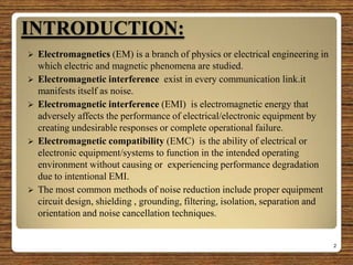
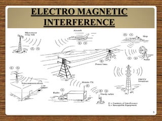
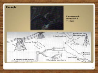
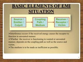
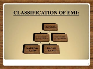
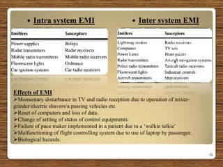
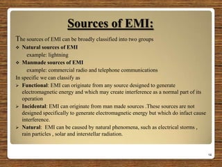
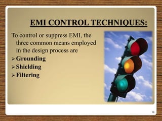


The document provides an overview of electromagnetic interference (EMI) and electromagnetic compatibility (EMC), explaining their definitions, sources, effects, and mitigation techniques. It emphasizes the importance of EMI control through methods such as grounding, shielding, and filtering, as well as the necessity for EMC standards to ensure effective operation in shared electromagnetic environments. Additionally, it highlights the ongoing need for research in the field of EMC to address unresolved challenges.


