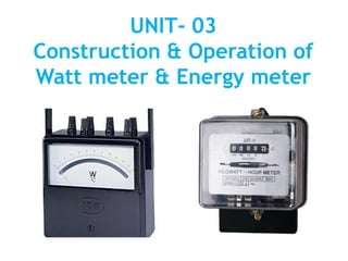
Unit 03 Construction & Operation of Watt meter & Energy meter
•
34 likes•11,887 views

An induction watt-hour meter measures electrical energy consumption by using two electromagnets to induce eddy currents in an aluminum disk and rotate it. The disk's rotation is proportional to energy used and is registered to indicate kilowatt-hours. It works by using a series coil carrying load current and a shunt coil carrying voltage-proportional current to generate a rotating magnetic field. This field interacts with eddy currents in the disk to provide a driving torque while a brake magnet provides a braking torque proportional to disk speed. Errors can occur due phase shifts or other issues, but the meter can be adjusted to ensure accurate readings.

Recommended
More Related Content
What's hot
What's hot (20)
Similar to Unit 03 Construction & Operation of Watt meter & Energy meter
Similar to Unit 03 Construction & Operation of Watt meter & Energy meter (20)
More from PremanandDesai
More from PremanandDesai (20)
Recently uploaded
Recently uploaded (20)
Unit 03 Construction & Operation of Watt meter & Energy meter
- 1. UNIT- 03 Construction & Operation of Watt meter & Energy meter
- 2. Wattmeter: A wattmeter, measures Electric Power of the given an Electric Apparatus or Circuit. • Types of wattmeter: 1. Electric-Dynamometer wattmeter - for both D.C and A.C power 2. Induction wattmeter - for A.C power only 3. Electrostatic type wattmeter - for small amount of A.C power and low power factor
- 3. Single phase electro-dynamometer (electro-dynamic ) type wattmeter
- 4. Principle: A electro-dynamometer wattmeter is used for the measurement for D.C as well as A.C power. “It works on the dynamometer principle i.e., mechanical force exists between two current carrying conductor or coils”.
- 5. Construction: • When a dynamometer instrument is used as a wattmeter, the fixed coils are connected in series with the load and carry the load current(Il), while the moving coil is connected across the load through a series multiplier R and carries a current(I2) proportional to the load voltage as shown in figure. • The fixed coil is called the current coil(CC)and the movable coil is known as potential coil(PC). The controlling torque is provided by two spiral springs which also serve the additional purpose of leading current into and out of the moving coil. Air friction damping is provided in such instruments. A pointer is attached to the movable coil.
- 6. Operation or working: • When the wattmeter is connected in the circuit to measure the power, the current coil carries load current and potential coil carries current proportional to the load voltage, due to currents in the coils, mechanical force exists between them. The result is that movable coil moves the pointer over the scale. The pointer comes to reset at a position where deflecting torque is equal to the controlling torque (reversals of current reverses current’s in both the fixed coils and the movable coil so that the direction of deflecting torque remains unchanged). • Deflecting torque; Td load power VICos φ ------ For A.C Supply VI1 ---------------For D.C Supply
- 7. Errors in watt meters: 1. Error due to pressure coil inductance. Due to self inductance, the pressure coil creates phase-shift in the current flowing through it. So the true angle between voltage and current slightly changed, which leads to an error in the readings. The wattmeter gives a higher reading for lagging load and lesser reading for leading pf load. A low value capacitor across a part of the multiplier will reduce the effect of pressure coil inductance
- 8. 2. Error due to pressure coil capacitance: The effect of pressure coil capacitance is opposite to that of inductance. The pressure coil current leads the supply voltage and causes the errors in reading. 3. Eddy current errors: In metal parts of the instrument the eddy current get produced. The eddy current interact with instrument current, to cause change in the deflecting torque to cause error, hence metal parts should be kept as minimum as possible. Also the resistivity of the metal parts used must be high to reduce the eddy current.
- 9. 4. Error due method of connection: There are two ways of connecting wattmeter in a given circuit Fig.a Fig.b • There are two possible connections possible based on the nature of load current, either the main and common can be shorted (called as MC short) or the load and common terminals can be shorted(called as LC short). • For high load current it advised to use the LC short combination as shown in figure. • In this case the current measured by the current coil is the load current plus the current through the voltage coil. The current taken by the voltage coil is a small percent of the total load current and hence the error introduced is small.
- 10. 5. Strong magnetic field error: Similar to moving coil instrument the operating field in electrodynamometer instrument is very weak. Hence, external magnetic can interact with operating field to cause change in deflection, causing the error. To reduce the effect of strong magnetic field, the shields must be used for instrument. 6. Temperature error: The temperature errors are caused due to the self heating of the coil, which causes change in the resistance of the coil. Thus temperature compensating resistors can be used in the precise instrument to eliminate the temperature errors.
- 11. 7. Frequency errors: The changes in the frequency causes to change self inductance of moving coil and fixed coil. This causes errors in the readings. The frequency error can be reduced by having equal time constants for both moving and fixed coil circuits. 8. Friction errors: As operating force is small, the friction in moving parts also can causes errors. This can be reduced by using light weight moving system with minimum friction.
- 12. Merits and de-merits of dynamometer type wattmeter • Merits: 1. They can be used for the measurement of A.C as well as D.C power. 2. They have uniform scale. 3. By careful design, high accuracy can be obtained. 4. Free from hysteresis errors. 5. Low power consumption. 6. Light in weight.
- 13. • Demerits: 1. At low power factor(p.f), the impedance of potential coil causes serious errors. 2. The reading of the instrument may be affected by strong magnetic fields(in order to prevent it, the instrument is shielded from the external magnetic field by enclosing it in a soft-iron case). 3. They are more expensive than other type of instruments. 4. These instruments are sensitive to overloads and mechanical impacts. Therefore care must be taken while handling them. 5. The operating current of these instruments is large due to the fact that they have weak magnetic field.
- 14. Measurement of Three Phase power by two wattmeter method:
- 15. • The best method of measuring power of three phase circuit, Whether the circuit is star connected or delta connected by using two single phase wattmeter which is called two wattmeter method of measurement of three phase power. • The current coil of the two wattmeter are connected in any two lines while the voltage coil of each wattmeter is connected between its own wattmeter coil terminal and a line without a current coil. • It can be shown that when two wattmeter's are connected in this way, the algebraic sum of the two wattmeter readings gives the total power dissipated in the three phase circuit.
- 16. If W1 and W2 are the wattmeter readings then total power W= W1+W2= Three phase power= 3 VLILCosφ Power factor calculation by two wattmeter method: In case of balanced load, the power factor can be calculated from W1 & W2 readings. For balanced, lagging p.f load, W1= VLILCos(30-φ) & W2= VLILCos(30-φ) W1+W2= 3VLILCosφ ----------------------- Eqn-1 W1-W2= VLIL[Cos(30-φ ) – Cos(30+φ )] =VLIL[Cos30.Cosφ + Sin30.Sinφ - cos30.Cosφ + Sin30.Sinφ] =VLIL[2 Sin30 Sinφ ] = VLIL[2 × 1 2 ×Sinφ] W1-W2= VLILSinφ ------------------------- Eqn-2
- 17. Taking ratio of Eqn-1 & Eqn-2 W1 −W2 W1 +W2 = VLIL Sinφ 3 VLIL cosφ W1 −W2 W1 +W2 = tan Ø 3 3(W1 −W2 ) (W1 +W2 ) = tan Ø Ø = tan-1 3(W1 −W2 ) W1 +W2 Power factor (p.f) = CosØ = Cos tan−1 3(W1 −W2 ) W1 +W2
- 18. Problems 1.A balanced Three Phase star connected load draws power from 440V supply the two wattmeter connected indicate W1=5KW & W2 = 1.2KW, calculate power, power Factor & current in the circuit. Given data : VL=440V , W1 = 5kW , W2 = 1.2kW Power (P) = ? Power factor (p.f) = ? , Current (I) = ? Solution : Power (P) = W1 + W2 = 1.2kW + 5kW P = 6.2 kW CosØ = Cos tan−1 3(W1−W2) W1+W2 = Cos tan−1 3 (5−1.2) (5+1.2) = Cos tan−1 (1.06157) CosØ = 0.6856 Lagging P = 3VLILCosφ 6.2×103 = 3 ×440 × IL × 0.6856 IL = 6.2×10³ 3 × 440 × 0.6856 IL = 11.866 Amps
- 19. 2.If the reading of the two wattmeter connected across the load are 250W & 1.5KW, Determine P.f of the load. Given : W1 =250, W2=1.5KW=1500W P.f = CosØ = ? Solution : CosØ = Cos tan−1 3(W1 −W2 ) W1 +W2 CosØ = Cos tan−1 3(250−1500) (250+1500) CosØ = 0.6286 leading
- 20. Calibration of wattmeter by comparison method using a standard meter:
- 21. • As shown in the above circuit diagram Calibration of wattmeter by comparison method using a standard meter, in this circuit diagram Wm is under Calibration meter and Ws is the Standard meter, Standard meter shows the accurate Power consumptions in the circuit and by comparing the both the value of the meters , error of the meter can be find and correct it. • The % error of the meters can be calculate by following formula. %Error= 𝑊 𝑚 −𝑊𝑠 𝑊 𝑠 ×100
- 22. Energy meter • An instrument used to measure the energy consumed in a given circuit is called an Energy meter. • An electrical energy can also be expressed in the unit watt-hour(wh) or Kilo watt-hour(Kwh). • Thus one Kilo watt-hour energy means the expenditure of 1 Kw power over a time interval of 1 hour. 1 Kwh = 1 unit of energy.
- 23. Types of Energy meters: 1. Electrolytic energy meters 2. Motor meters a) Mercury motor meters b) Commutator meters c) Induction energy meters i. 1- energy meters ii. 2- two element iii. 3- three element 3. Clock meters 4. Electronic energy meters
- 24. • Single phase induction type energy meter: 1- induction watt-hour meters (Energy Meters) are extensively used for the measurement of electrical energy in A.C circuit. An induction watt-hour meter is essentially an induction wattmeter with control spring and pointer removed but brake magnet and counting mechanism provided.
- 26. Principle : The basic principle of induction type energy meter is electromagnetic induction. When alternating current flow though two suitably located coils produces rotating magnetic field which is cut by the metallic disc suspended near to the coils thus EMF induce in the disc which is circulates eddy current in it. By interaction of rotating magnetic field and eddy currents, torque is developed and cause the disc rotate.
- 27. Construction: An induction type single phase energy meter, as show in fig has following main parts of the operating mechanism. • Driving system. • Moving system. • Breaking system. • Recording mechanism.
- 28. • Driving system. It consists of two electromagnets, called “shunt” magnet and “series” magnet, Series magnet: it consists of a number of U-shaped laminations of silicon steel together to form a core. A coil of thick wire having a few turns is wounded in both legs of U- shaped magnet. the coil is known is current coil which is connected series with load. Produce the magnetic field proportional and in phase with line current I. Shunt magnet: it consists of number of M-shaped laminations of silicon steel assembled together to form a core. A coil of thin wire having large number of turn in wound on central limb of the magnet. this coil is connected across the load. thus it is excited by current proportional to the supply voltage and known is potential coil.
- 29. • Moving system. The moving system essentially consists of a light rotating aluminium disk mounted on a vertical spindle or shaft. The shaft that supports the aluminium disk is connected by a gear arrangement to the clock mechanism on the front of the meter to provide information that consumed energy by the load. The time varying (sinusoidal) fluxes produced by shunt and series magnet induce eddy currents in the aluminium disc. The interaction between these two magnetic fields and eddy currents set up a driving torque in the disc. The number of rotations of the disk is therefore proportional to the energy consumed by the load in a certain time interval and is commonly measured in kilowatt-hours (kWh).
- 30. • Breaking system. Damping of the disk is provided by a small permanent magnet, located diametrically opposite to the a.c magnets. The disk passes between the magnet gaps. The movement of rotating disc through the magnetic field crossing the air gap sets up eddy currents in the disc that reacts with the magnetic field and exerts a braking torque. By changing the position of the brake magnet or diverting some of the flux there form, the speed of the rotating disc can be controlled. • Recording mechanism. The function of recording or registering mechanism is to record continuously a number on the dial which is proportional to the revolutions made by the moving system. the no of revolution on the disc is a measured the electrical energy passing though the meter.
- 31. • Operation : When the energy meter is connected in circuit, the current coil carries the load current and pressure coil carries the current proportional to the supply voltage. the magnetic field produced by series magnetic in phase with the line current and magnetic field produced by shunt magnet is in quadrature with the applied voltage. thus, a phase difference exists between the fluxes produce by the two coils. this setup rotating magnetic field which interacts with disc and produce a driving torque and thus, disc starts rotating. the number of revolutions made by the disc depend upon energy passing though the meter. the spindle geared to the recording mechanism so that energy consumed in the circuit is directly registered in kWh. The speed of the disc is adjusted by adjusting the position of braking magnet. example, if the energy meter registers less energy than the energy actual consumed in the circuit. then the speed of disc has to be increased which is obtained by sifting the braking magnet nearer to the centre of the disc vice -versa.
- 32. When induction watt-hour meter is connected in the circuit to measure energy, the shunt carries current proportional to the supply voltage & the series magnet carries the load current. Therefore, Driving torque, Td VCSin VI Sin (900 -) VI Cos Power The breaking torque is due to the eddy currents induced in the aluminium disc. Since the magnitude of eddy current is proportional to the disc speed, the braking torque will also be proportional to the disc speed ‘n’ i.e.,
- 33. Braking torque, IB n For steady speed of rotation, Td = TB Power n Multiplying both side by t, The for which power is supplied, Power × t n × t Energy N Where N(=n×t) is the total number of revolutions in time ‘t’. The conducting mechanism is so arranged that the meter indicates(Kwh) directly & not the revolutions.
- 34. • Meter constant, N Energy N= K Energy Where, K is a constsnt called meter constant. K= N Energy = No.of revolutions Kwh • Hence the number of revolutions made by the disc for 1 Kwh of energy consumption is called meter constant.
- 35. Errors and adjustments in single phase induction type energy meter Errors: 1. Phase Error 2. Speed Error 3. Frictional Error 4. Creeping 5. Temperature Error 6. Frequency Error 7. Voltage Error
- 36. 1. Phase Error: The meter will read correctly only if the shunt magnet flux lags behind the supply voltage by exactly 90. Since the shunt magnet coil has some resistance and is not completely reactive, the shunt magnet flux does not lag the supply voltage by exactly 90. The result is that the meter will not read correctly at all power factors. Adjustment: The flux in the shunt magnet can be made to lag behind the supply voltage by exactly 90 by adjusting the position of the shading coil placed around the lower part of the central limb of the shunt magnet.
- 37. 2. Speed Error: Sometimes the speed of the disc of the meter is either fast or slow, resulting in the wrong recording of energy consumption. Adjustment: The speed of the energy meter can be adjusted to the desired value by changing the position of the brake magnet.
- 38. 3. Frictional Error: Frictional forces at the rotor bearings & in the counting mechanism cause noticeable Error especially at light loads. At light loads, the torque due to friction adds considerably to the braking torque. Since friction torque is not proportional to the speed but is roughly constant, it can cause considerable error in meter reading. Adjustment: In order to compensate for this error, it is necessary to provide a constant addition to the driving torque that is equal & opposite to the friction torque.
- 39. 4. Creeping: sometimes the disc of the meter makes slow but continuous rotation i.e., when potential coil is excited but with no- current flowing in the load this is called creeping. This error may caused due to over compensation for friction, excessive supply voltage, vibrations, strong magnetic field etc. Adjustment: In order to prevent this creeping two diametrically opposite holes are filled in the disc, this causes sufficient distortion of the field. The result is that the disc tends to remain stationary when one of holes comes under one of the poles of the shunt magnet.
- 40. 5. Temperature Error: Since watt-hour meters are frequency required to operate on outdoor installations and are subjected to extreme temperatures, the effects of temperature & their compensation are very important. The resistance of the disc, of the potential coil & characteristics of magnetic circuit & the strength of brake magnet are affected by the changes in temperature, therefore great case is exercised in the design of the meter to eliminate the errors due to temperature variations.
- 41. 6. Frequency variations: The meter is designed to give minimum error at a particular frequency (generally 50 Hz). If the supply frequency changes, the reactance of the coils also changes, resulting in a small error. Fortunately, this is not of much signification because commercial torque are held within close limits. 7. Voltage variations: The shunt magnet flux will increase with an increase in voltage. The driving torque is proportional to the first power of flux where as braking torque is proportional to the square if the flux. The small error due to voltage variations can be eliminated by the proper design of the magnet circuit of the shunt magnet.
- 42. Calibration of single phase energy meter
- 43. • Before the energy meter is used for measurement of energy in any circuit, it has to be calibrated, so that the indicated energy , is approximately equal to the actual consumed energy, within reasonable limits of error +5%. • Connections are made as shown in above figure & the applying load, note down the energy meter reading in- terms of revolutions & converted into Kwh (Ei) by multiplying the energy meter constant & note down the wattmeter reading & multiplying the wattmeter constant & time to the wattmeter readings, this will be in terms of Kwh(Ea). & find The error using formula- % Error = 𝐸𝑖−𝐸𝑎 𝐸 𝑎 × 100
- 44. Problems on errors in energy meter 1. The meter constant of 230V,10A energy meter is 1000rev/Kwh . The meter is tested at half load and rated voltage at unity p.f. and found to make 40rev in 65sec.Determine meter error at half load. Given data : V=230V , I = 10A Energy meter Constant (K) = 1000rev/Kwh Time (t) taken for 40 Revolution = 65 Seconds Error for half load = ? Solution: Half Load (Current)= 10 2 = 5A Actual Energy consumed (Ea) = V × I × cosØ × t = 230 × 5 × 1 × 65 = 74750 Watt-seconds = 𝑤𝑎𝑡𝑡−𝑠𝑒𝑐𝑜𝑛𝑑𝑠 60×60 𝐾𝑤 = 74750 3600 ×103 = 0.04408 Kwh Energy consumed Showing by meter(Es) = No.of Revolutions K = 40 1000 = 0.04 Kwh % Error = 𝐸𝑠 −𝐸𝑎 𝐸𝑎 = 0.040 −0.044 0.044 = 𝟎. 𝟎𝟗𝟐𝟓%
- 45. 2. A 50A , 230V energy meter on full load test makes 61 rev/37 seconds. If the meter constant is 520 rev/Kwh , What is the %age error ? Answer : 0.8 % 3.The meter constant of a 230 V, 10A energy meter is 1800 rev/kwh. The meter is tested at half load & rated voltage & unity p.f The meter is found to make 80 rev/138 sec. Determine the meter error at half load. Answer : 0.817%
- 46. Model Questions • Cognitive Level: UNDERSTAND 1. Explain the construction and operation of a dynamometer type wattmeter a with neat diagram. 2. Explain the construction and operation of single phase induction type energy meter with a neat diagram. 3. Describe the calibration of wattmeter with a neat circuit diagram. 4. List the any 3 errors in watt meters. • Cognitive Level: APPLICATION 1. If the reading s of the two watt meters connected across the load are 250W and 1.5KW,determinep.f. of the load. 2. The meter constant of 230V,10A energy meter is 1000rev/Kwh.The meter is tested at half load and rated voltage at unity p.f.and found to make 40rev in 65sec.Determine meter error at half load. 3. Describe the calibration of energy meter with a neat circuit diagram.