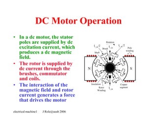
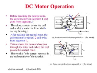
electrical machine1 J Role@ueab 2006
DC
Motors
electrical machine1 J Role@ueab 2006
DC Motor
• The direct current (dc) machine can be used as
a motor or as a generator.
• DC Machine is most often used for a motor.
• The major advantages of dc machines are the
easy speed and torque regulation.
• However, their application is limited to mills,
mines and trains. As examples, trolleys and
underground subway cars may use dc motors.
• In the past, automobiles were equipped with dc
dynamos to charge their batteries.
electrical machine1 J Role@ueab 2006
DC Motor
• Even today the starter is a series dc motor
• However, the recent development of power
electronics has reduced the use of dc motors
and generators.
• The electronically controlled ac drives are
gradually replacing the dc motor drives in
factories.
• Nevertheless, a large number of dc motors are
still used by industry and several thousand are
sold annually.
electrical machine1 J Role@ueab 2006
Construction
electrical machine1 J Role@ueab 2006
DC Machine Construction
Figure 8.1 General arrangement of a dc machine
electrical machine1 J Role@ueab 2006
DC Machines
• The stator of the dc motor has
poles, which are excited by dc
current to produce magnetic
fields.
• In the neutral zone, in the middle
between the poles, commutating
poles are placed to reduce
sparking of the commutator. The
commutating poles are supplied
by dc current.
• Compensating windings are
mounted on the main poles.
These short-circuited windings
damp rotor oscillations. .
electrical machine1 J Role@ueab 2006
DC Machines
• The poles are mounted on an
iron core that provides a
closed magnetic circuit.
• The motor housing supports
the iron core, the brushes and
the bearings.
• The rotor has a ring-shaped
laminated iron core with slots.
• Coils with several turns are
placed in the slots. The
distance between the two legs
of the coil is about 180 electric
degrees.
electrical machine1 J Role@ueab 2006
DC Machines
• The coils are connected in series
through the commutator
segments.
• The ends of each coil are
connected to a commutator
segment.
• The commutator consists of
insulated copper segments
mounted on an insulated tube.
• Two brushes are pressed to the
commutator to permit current
flow.
• The brushes are placed in the
neutral zone, where the magnetic
field is close to zero, to reduce
arcing.
electrical machine1 J Role@ueab 2006
DC Machines
• The rotor has a ring-shaped
laminated iron core with slots.
• The commutator consists of
insulated copper segments
mounted on an insulated tube.
• Two brushes are pressed to
the commutator to permit
current flow.
• The brushes are placed in the
neutral zone, where the
magnetic field is close to zero,
to reduce arcing.
electrical machine1 J Role@ueab 2006
DC Machines
• The commutator switches the
current from one rotor coil to
the adjacent coil,
• The switching requires the
interruption of the coil
current.
• The sudden interruption of an
inductive current generates
high voltages .
• The high voltage produces
flashover and arcing between
the commutator segment and
the brush.
electrical machine1 J Role@ueab 2006
DC Machine Construction
|
Shaft
Brush
Copper
segment
Insulation
Rotor
Winding
N S
Ir_dc
Ir_dc
/2
Rotation
Ir_dc
/2
Ir_dc
1
2
3
4
5
6
7
8
Pole
winding
Figure 8.2 Commutator with the rotor coils connections.
electrical machine1 J Role@ueab 2006
DC Machine Construction
Figure 8.3 Details of the commutator of a dc motor.
electrical machine1 J Role@ueab 2006
DC Machine Construction
Figure 8.4 DC motor stator with poles visible.
electrical machine1 J Role@ueab 2006
DC Machine Construction
Figure 8.5 Rotor of a dc motor.
electrical machine1 J Role@ueab 2006
DC Machine Construction
Figure 8.6 Cutaway view of a dc motor.
electrical machine1 J Role@ueab 2006
DC Motor Operation
electrical machine1 J Role@ueab 2006
DC Motor Operation
• In a dc motor, the stator
poles are supplied by dc
excitation current, which
produces a dc magnetic
field.
• The rotor is supplied by
dc current through the
brushes, commutator
and coils.
• The interaction of the
magnetic field and rotor
current generates a force
that drives the motor
|
Shaft
Brush
Copper
segment
Insulation
Rotor
Winding
N S
Ir_dc
Ir_dc
/2
Rotation
Ir_dc
/2
Ir_dc
1
2
3
4
5
6
7
8
Pole
winding
electrical machine1 J Role@ueab 2006
DC Motor Operation
• The magnetic field lines
enter into the rotor from the
north pole (N) and exit
toward the south pole (S).
• The poles generate a
magnetic field that is
perpendicular to the current
carrying conductors.
• The interaction between the
field and the current
produces a Lorentz force,
• The force is perpendicular to
both the magnetic field and
conductor
(a) Rotor current flow from segment 1 to 2 (slot a to b)
Vdc
30
N
S
B
v
v
a
b
1
2
Ir_dc
(b) Rotor current flow from segment 2 to 1 (slot b to a)
30
N
S Vdc
a
b
1
2
B
v v
Ir_dc
electrical machine1 J Role@ueab 2006
DC Motor Operation
• The generated force turns the rotor
until the coil reaches the neutral
point between the poles.
• At this point, the magnetic field
becomes practically zero together
with the force.
• However, inertia drives the motor
beyond the neutral zone where the
direction of the magnetic field
reverses.
• To avoid the reversal of the force
direction, the commutator changes
the current direction, which
maintains the counterclockwise
rotation. .
(a) Rotor current flow from segment 1 to 2 (slot a to b)
Vdc
30
N
S
B
v
v
a
b
1
2
Ir_dc
(b) Rotor current flow from segment 2 to 1 (slot b to a)
30
N
S Vdc
a
b
1
2
B
v v
Ir_dc
electrical machine1 J Role@ueab 2006
DC Motor Operation
• Before reaching the neutral zone,
the current enters in segment 1 and
exits from segment 2,
• Therefore, current enters the coil
end at slot a and exits from slot b
during this stage.
• After passing the neutral zone, the
current enters segment 2 and exits
from segment 1,
• This reverses the current direction
through the rotor coil, when the coil
passes the neutral zone.
• The result of this current reversal is
the maintenance of the rotation.
(a) Rotor current flow from segment 1 to 2 (slot a to b)
Vdc
30
N
S
B
v
v
a
b
1
2
Ir_dc
(b) Rotor current flow from segment 2 to 1 (slot b to a)
30
N
S Vdc
a
b
1
2
B
v v
Ir_dc
electrical machine1 J Role@ueab 2006
DC Generator
Operation
electrical machine1 J Role@ueab 2006
DC Generator Operation
• The N-S poles produce a
dc magnetic field and the
rotor coil turns in this
field.
• A turbine or other
machine drives the rotor.
• The conductors in the
slots cut the magnetic flux
lines, which induce
voltage in the rotor coils.
• The coil has two sides:
one is placed in slot a, the
other in slot b.
30
N
S Vdc
B
v
v
a
b
1
2
Ir_dc
(a) Rotor current flow from segment 1 to 2 (slot a to b)
30
N
S Vdc
a
b
1
2
v
v
B
Ir_dc
(b) Rotor current flow from segment 2 to 1 (slot b to a)
electrical machine1 J Role@ueab 2006
DC Generator Operation
• In Figure 8.11A, the
conductors in slot a are
cutting the field lines
entering into the rotor
from the north pole,
• The conductors in slot b
are cutting the field lines
exiting from the rotor to
the south pole.
• The cutting of the field
lines generates voltage in
the conductors.
• The voltages generated in
the two sides of the coil
are added.
30
N
S Vdc
B
v
v
a
b
1
2
Ir_dc
(a) Rotor current flow from segment 1 to 2 (slot a to b)
30
N
S Vdc
a
b
1
2
v
v
B
Ir_dc
(b) Rotor current flow from segment 2 to 1 (slot b to a)
electrical machine1 J Role@ueab 2006
DC Generator Operation
• The induced voltage is
connected to the generator
terminals through the
commutator and brushes.
• In Figure 8.11A, the induced
voltage in b is positive, and in
a is negative.
• The positive terminal is
connected to commutator
segment 2 and to the
conductors in slot b.
• The negative terminal is
connected to segment 1 and
to the conductors in slot a.
30
N
S Vdc
B
v
v
a
b
1
2
Ir_dc
(a) Rotor current flow from segment 1 to 2 (slot a to b)
30
N
S Vdc
a
b
1
2
v
v
B
Ir_dc
(b) Rotor current flow from segment 2 to 1 (slot b to a)
electrical machine1 J Role@ueab 2006
DC Generator Operation
• When the coil passes the
neutral zone:
– Conductors in slot a are
then moving toward the
south pole and cut flux lines
exiting from the rotor
– Conductors in slot b cut the
flux lines entering the in
slot b.
• This changes the polarity
of the induced voltage in
the coil.
• The voltage induced in a
is now positive, and in b is
negative.
30
N
S Vdc
B
v
v
a
b
1
2
Ir_dc
(a) Rotor current flow from segment 1 to 2 (slot a to b)
30
N
S Vdc
a
b
1
2
v
v
B
Ir_dc
(b) Rotor current flow from segment 2 to 1 (slot b to a)
electrical machine1 J Role@ueab 2006
DC Generator Operation
• The simultaneously the
commutator reverses its
terminals, which assures
that the output voltage
(Vdc) polarity is
unchanged.
• In Figure 8.11B
– the positive terminal is
connected to commutator
segment 1 and to the
conductors in slot a.
– The negative terminal is
connected to segment 2 and
to the conductors in slot b.
30
N
S Vdc
B
v
v
a
b
1
2
Ir_dc
(a) Rotor current flow from segment 1 to 2 (slot a to b)
30
N
S Vdc
a
b
1
2
v
v
B
Ir_dc
(b) Rotor current flow from segment 2 to 1 (slot b to a)
electrical machine1 J Role@ueab 2006
DC Machine
Equivalent Circuit
electrical machine1 J Role@ueab 2006
Generator
electrical machine1 J Role@ueab 2006
DC Generator Equivalent circuit
• The magnetic field produced by the stator poles induces a
voltage in the rotor (or armature) coils when the
generator is rotated.
• This induced voltage is represented by a voltage source.
• The stator coil has resistance, which is connected in
series.
• The pole flux is produced by the DC excitation/field
current, which is magnetically coupled to the rotor
• The field circuit has resistance and a source
• The voltage drop on the brushes represented by a battery
electrical machine1 J Role@ueab 2006
DC Generator Equivalent circuit
• Figure 8.12Equivalent circuit of a separately excited dc
generator.
Rf
Ra
Vbrush
Vdc
Eag
Vf
max
If
Iag
Load
Mechanical
power in
Electrical
power out
electrical machine1 J Role@ueab 2006
DC Generator Equivalent circuit
• The magnetic field produced by the stator poles
induces a voltage in the rotor (or armature) coils
when the generator is rotated.
• The dc field current of the poles generates a
magnetic flux
• The flux is proportional with the field current if
the iron core is not saturated:
f
ag I
K1


electrical machine1 J Role@ueab 2006
DC Generator Equivalent circuit
• The rotor conductors cut the field lines that
generate voltage in the coils.
• The motor speed and flux equations are :
v
B
N
E g
r
ag 
2

2
g
D
v 
 g
g
ag D
B 


electrical machine1 J Role@ueab 2006
DC Generator Equivalent circuit
• The combination of the three equation
results the induced voltage equation:
• The equation is simplified.
  

 ag
r
g
g
r
g
g
r
g
r
ag N
D
B
N
D
B
N
v
B
N
E 











 


2
2
2


 f
m
f
r
ag
r
ag I
K
I
K
N
N
E 


 1
electrical machine1 J Role@ueab 2006
DC Generator Equivalent circuit
• When the generator is loaded, the load current produces
a voltage drop on the rotor winding resistance.
• In addition, there is a more or less constant 1–3 V voltage
drop on the brushes.
• These two voltage drops reduce the terminal voltage of
the generator. The terminal voltage is;
brush
a
ag
dc
ag V
R
I
V
E 


electrical machine1 J Role@ueab 2006
Motor
electrical machine1 J Role@ueab 2006
DC Motor Equivalent circuit
• Figure 8.13 Equivalent circuit of a separately excited dc motor
• Equivalent circuit is similar to the generator only the current
directions are different
Rf
Ra
Vbrush
Vdc
Eam
Vf
max
If
Iam
Mechanical
power out
Electrical
power in
DC Power
supply
electrical machine1 J Role@ueab 2006
DC Motor Equivalent circuit
• The operation equations are:
• Armature voltage equation
brush
a
am
am
dc V
R
I
E
V 


The induced voltage and motor speed vs angular
frequency

f
m
am I
K
E 
m
n

 2

electrical machine1 J Role@ueab 2006
DC Motor Equivalent circuit
• The operation equations are:
• The combination of the equations results in
The current is calculated from this equation. The output
power and torque are:
m
am
dc
am
f
m R
I
V
E
I
K 



am
am
out I
E
P  f
am
m
out
I
I
K
P
T 


electrical machine1 J Role@ueab 2006
DC Machine
Excitation Methods
electrical machine1 J Role@ueab 2006
DC Motor Operation
• There are four different methods for
supplying the dc current to the motor or
generator poles:
– Separate excitation;
– Shunt connection
– Series connection
– Compound
electrical machine1 J Role@ueab 2006
DC Motor Equivalent circuit
• Figure 8.14 Equivalent circuit of a shunt dc motor
DC Power
supply
Vdc
Eam
Iam
max Rf
If
Ra
Vbrush
Im
Pout
electrical machine1 J Role@ueab 2006
DC Motor Equivalent circuit
• Figure 8.15 Equivalent circuit of a series dc motor
Vdc
Eam
Rf
Ra
Vbrush
Im
max
DC Power
supply
Pout
electrical machine1 J Role@ueab 2006
DC Motor Equivalent circuit
• Figure 8.16 Equivalent circuit of a compound dc motor
Vdc
Eam
Rfs
Ra
Vbrush
Im
max
DC Power
supply
Rfp
Iam
Ifp
Pout

4403224.ppt

  • 1.
    electrical machine1 JRole@ueab 2006 DC Motors
  • 2.
    electrical machine1 JRole@ueab 2006 DC Motor • The direct current (dc) machine can be used as a motor or as a generator. • DC Machine is most often used for a motor. • The major advantages of dc machines are the easy speed and torque regulation. • However, their application is limited to mills, mines and trains. As examples, trolleys and underground subway cars may use dc motors. • In the past, automobiles were equipped with dc dynamos to charge their batteries.
  • 3.
    electrical machine1 JRole@ueab 2006 DC Motor • Even today the starter is a series dc motor • However, the recent development of power electronics has reduced the use of dc motors and generators. • The electronically controlled ac drives are gradually replacing the dc motor drives in factories. • Nevertheless, a large number of dc motors are still used by industry and several thousand are sold annually.
  • 4.
    electrical machine1 JRole@ueab 2006 Construction
  • 5.
    electrical machine1 JRole@ueab 2006 DC Machine Construction Figure 8.1 General arrangement of a dc machine
  • 6.
    electrical machine1 JRole@ueab 2006 DC Machines • The stator of the dc motor has poles, which are excited by dc current to produce magnetic fields. • In the neutral zone, in the middle between the poles, commutating poles are placed to reduce sparking of the commutator. The commutating poles are supplied by dc current. • Compensating windings are mounted on the main poles. These short-circuited windings damp rotor oscillations. .
  • 7.
    electrical machine1 JRole@ueab 2006 DC Machines • The poles are mounted on an iron core that provides a closed magnetic circuit. • The motor housing supports the iron core, the brushes and the bearings. • The rotor has a ring-shaped laminated iron core with slots. • Coils with several turns are placed in the slots. The distance between the two legs of the coil is about 180 electric degrees.
  • 8.
    electrical machine1 JRole@ueab 2006 DC Machines • The coils are connected in series through the commutator segments. • The ends of each coil are connected to a commutator segment. • The commutator consists of insulated copper segments mounted on an insulated tube. • Two brushes are pressed to the commutator to permit current flow. • The brushes are placed in the neutral zone, where the magnetic field is close to zero, to reduce arcing.
  • 9.
    electrical machine1 JRole@ueab 2006 DC Machines • The rotor has a ring-shaped laminated iron core with slots. • The commutator consists of insulated copper segments mounted on an insulated tube. • Two brushes are pressed to the commutator to permit current flow. • The brushes are placed in the neutral zone, where the magnetic field is close to zero, to reduce arcing.
  • 10.
    electrical machine1 JRole@ueab 2006 DC Machines • The commutator switches the current from one rotor coil to the adjacent coil, • The switching requires the interruption of the coil current. • The sudden interruption of an inductive current generates high voltages . • The high voltage produces flashover and arcing between the commutator segment and the brush.
  • 11.
    electrical machine1 JRole@ueab 2006 DC Machine Construction | Shaft Brush Copper segment Insulation Rotor Winding N S Ir_dc Ir_dc /2 Rotation Ir_dc /2 Ir_dc 1 2 3 4 5 6 7 8 Pole winding Figure 8.2 Commutator with the rotor coils connections.
  • 12.
    electrical machine1 JRole@ueab 2006 DC Machine Construction Figure 8.3 Details of the commutator of a dc motor.
  • 13.
    electrical machine1 JRole@ueab 2006 DC Machine Construction Figure 8.4 DC motor stator with poles visible.
  • 14.
    electrical machine1 JRole@ueab 2006 DC Machine Construction Figure 8.5 Rotor of a dc motor.
  • 15.
    electrical machine1 JRole@ueab 2006 DC Machine Construction Figure 8.6 Cutaway view of a dc motor.
  • 16.
    electrical machine1 JRole@ueab 2006 DC Motor Operation
  • 17.
    electrical machine1 JRole@ueab 2006 DC Motor Operation • In a dc motor, the stator poles are supplied by dc excitation current, which produces a dc magnetic field. • The rotor is supplied by dc current through the brushes, commutator and coils. • The interaction of the magnetic field and rotor current generates a force that drives the motor | Shaft Brush Copper segment Insulation Rotor Winding N S Ir_dc Ir_dc /2 Rotation Ir_dc /2 Ir_dc 1 2 3 4 5 6 7 8 Pole winding
  • 18.
    electrical machine1 JRole@ueab 2006 DC Motor Operation • The magnetic field lines enter into the rotor from the north pole (N) and exit toward the south pole (S). • The poles generate a magnetic field that is perpendicular to the current carrying conductors. • The interaction between the field and the current produces a Lorentz force, • The force is perpendicular to both the magnetic field and conductor (a) Rotor current flow from segment 1 to 2 (slot a to b) Vdc 30 N S B v v a b 1 2 Ir_dc (b) Rotor current flow from segment 2 to 1 (slot b to a) 30 N S Vdc a b 1 2 B v v Ir_dc
  • 19.
    electrical machine1 JRole@ueab 2006 DC Motor Operation • The generated force turns the rotor until the coil reaches the neutral point between the poles. • At this point, the magnetic field becomes practically zero together with the force. • However, inertia drives the motor beyond the neutral zone where the direction of the magnetic field reverses. • To avoid the reversal of the force direction, the commutator changes the current direction, which maintains the counterclockwise rotation. . (a) Rotor current flow from segment 1 to 2 (slot a to b) Vdc 30 N S B v v a b 1 2 Ir_dc (b) Rotor current flow from segment 2 to 1 (slot b to a) 30 N S Vdc a b 1 2 B v v Ir_dc
  • 20.
    electrical machine1 JRole@ueab 2006 DC Motor Operation • Before reaching the neutral zone, the current enters in segment 1 and exits from segment 2, • Therefore, current enters the coil end at slot a and exits from slot b during this stage. • After passing the neutral zone, the current enters segment 2 and exits from segment 1, • This reverses the current direction through the rotor coil, when the coil passes the neutral zone. • The result of this current reversal is the maintenance of the rotation. (a) Rotor current flow from segment 1 to 2 (slot a to b) Vdc 30 N S B v v a b 1 2 Ir_dc (b) Rotor current flow from segment 2 to 1 (slot b to a) 30 N S Vdc a b 1 2 B v v Ir_dc
  • 21.
    electrical machine1 JRole@ueab 2006 DC Generator Operation
  • 22.
    electrical machine1 JRole@ueab 2006 DC Generator Operation • The N-S poles produce a dc magnetic field and the rotor coil turns in this field. • A turbine or other machine drives the rotor. • The conductors in the slots cut the magnetic flux lines, which induce voltage in the rotor coils. • The coil has two sides: one is placed in slot a, the other in slot b. 30 N S Vdc B v v a b 1 2 Ir_dc (a) Rotor current flow from segment 1 to 2 (slot a to b) 30 N S Vdc a b 1 2 v v B Ir_dc (b) Rotor current flow from segment 2 to 1 (slot b to a)
  • 23.
    electrical machine1 JRole@ueab 2006 DC Generator Operation • In Figure 8.11A, the conductors in slot a are cutting the field lines entering into the rotor from the north pole, • The conductors in slot b are cutting the field lines exiting from the rotor to the south pole. • The cutting of the field lines generates voltage in the conductors. • The voltages generated in the two sides of the coil are added. 30 N S Vdc B v v a b 1 2 Ir_dc (a) Rotor current flow from segment 1 to 2 (slot a to b) 30 N S Vdc a b 1 2 v v B Ir_dc (b) Rotor current flow from segment 2 to 1 (slot b to a)
  • 24.
    electrical machine1 JRole@ueab 2006 DC Generator Operation • The induced voltage is connected to the generator terminals through the commutator and brushes. • In Figure 8.11A, the induced voltage in b is positive, and in a is negative. • The positive terminal is connected to commutator segment 2 and to the conductors in slot b. • The negative terminal is connected to segment 1 and to the conductors in slot a. 30 N S Vdc B v v a b 1 2 Ir_dc (a) Rotor current flow from segment 1 to 2 (slot a to b) 30 N S Vdc a b 1 2 v v B Ir_dc (b) Rotor current flow from segment 2 to 1 (slot b to a)
  • 25.
    electrical machine1 JRole@ueab 2006 DC Generator Operation • When the coil passes the neutral zone: – Conductors in slot a are then moving toward the south pole and cut flux lines exiting from the rotor – Conductors in slot b cut the flux lines entering the in slot b. • This changes the polarity of the induced voltage in the coil. • The voltage induced in a is now positive, and in b is negative. 30 N S Vdc B v v a b 1 2 Ir_dc (a) Rotor current flow from segment 1 to 2 (slot a to b) 30 N S Vdc a b 1 2 v v B Ir_dc (b) Rotor current flow from segment 2 to 1 (slot b to a)
  • 26.
    electrical machine1 JRole@ueab 2006 DC Generator Operation • The simultaneously the commutator reverses its terminals, which assures that the output voltage (Vdc) polarity is unchanged. • In Figure 8.11B – the positive terminal is connected to commutator segment 1 and to the conductors in slot a. – The negative terminal is connected to segment 2 and to the conductors in slot b. 30 N S Vdc B v v a b 1 2 Ir_dc (a) Rotor current flow from segment 1 to 2 (slot a to b) 30 N S Vdc a b 1 2 v v B Ir_dc (b) Rotor current flow from segment 2 to 1 (slot b to a)
  • 27.
    electrical machine1 JRole@ueab 2006 DC Machine Equivalent Circuit
  • 28.
    electrical machine1 JRole@ueab 2006 Generator
  • 29.
    electrical machine1 JRole@ueab 2006 DC Generator Equivalent circuit • The magnetic field produced by the stator poles induces a voltage in the rotor (or armature) coils when the generator is rotated. • This induced voltage is represented by a voltage source. • The stator coil has resistance, which is connected in series. • The pole flux is produced by the DC excitation/field current, which is magnetically coupled to the rotor • The field circuit has resistance and a source • The voltage drop on the brushes represented by a battery
  • 30.
    electrical machine1 JRole@ueab 2006 DC Generator Equivalent circuit • Figure 8.12Equivalent circuit of a separately excited dc generator. Rf Ra Vbrush Vdc Eag Vf max If Iag Load Mechanical power in Electrical power out
  • 31.
    electrical machine1 JRole@ueab 2006 DC Generator Equivalent circuit • The magnetic field produced by the stator poles induces a voltage in the rotor (or armature) coils when the generator is rotated. • The dc field current of the poles generates a magnetic flux • The flux is proportional with the field current if the iron core is not saturated: f ag I K1  
  • 32.
    electrical machine1 JRole@ueab 2006 DC Generator Equivalent circuit • The rotor conductors cut the field lines that generate voltage in the coils. • The motor speed and flux equations are : v B N E g r ag  2  2 g D v   g g ag D B   
  • 33.
    electrical machine1 JRole@ueab 2006 DC Generator Equivalent circuit • The combination of the three equation results the induced voltage equation: • The equation is simplified.      ag r g g r g g r g r ag N D B N D B N v B N E                 2 2 2    f m f r ag r ag I K I K N N E     1
  • 34.
    electrical machine1 JRole@ueab 2006 DC Generator Equivalent circuit • When the generator is loaded, the load current produces a voltage drop on the rotor winding resistance. • In addition, there is a more or less constant 1–3 V voltage drop on the brushes. • These two voltage drops reduce the terminal voltage of the generator. The terminal voltage is; brush a ag dc ag V R I V E   
  • 35.
    electrical machine1 JRole@ueab 2006 Motor
  • 36.
    electrical machine1 JRole@ueab 2006 DC Motor Equivalent circuit • Figure 8.13 Equivalent circuit of a separately excited dc motor • Equivalent circuit is similar to the generator only the current directions are different Rf Ra Vbrush Vdc Eam Vf max If Iam Mechanical power out Electrical power in DC Power supply
  • 37.
    electrical machine1 JRole@ueab 2006 DC Motor Equivalent circuit • The operation equations are: • Armature voltage equation brush a am am dc V R I E V    The induced voltage and motor speed vs angular frequency  f m am I K E  m n   2 
  • 38.
    electrical machine1 JRole@ueab 2006 DC Motor Equivalent circuit • The operation equations are: • The combination of the equations results in The current is calculated from this equation. The output power and torque are: m am dc am f m R I V E I K     am am out I E P  f am m out I I K P T   
  • 39.
    electrical machine1 JRole@ueab 2006 DC Machine Excitation Methods
  • 40.
    electrical machine1 JRole@ueab 2006 DC Motor Operation • There are four different methods for supplying the dc current to the motor or generator poles: – Separate excitation; – Shunt connection – Series connection – Compound
  • 41.
    electrical machine1 JRole@ueab 2006 DC Motor Equivalent circuit • Figure 8.14 Equivalent circuit of a shunt dc motor DC Power supply Vdc Eam Iam max Rf If Ra Vbrush Im Pout
  • 42.
    electrical machine1 JRole@ueab 2006 DC Motor Equivalent circuit • Figure 8.15 Equivalent circuit of a series dc motor Vdc Eam Rf Ra Vbrush Im max DC Power supply Pout
  • 43.
    electrical machine1 JRole@ueab 2006 DC Motor Equivalent circuit • Figure 8.16 Equivalent circuit of a compound dc motor Vdc Eam Rfs Ra Vbrush Im max DC Power supply Rfp Iam Ifp Pout