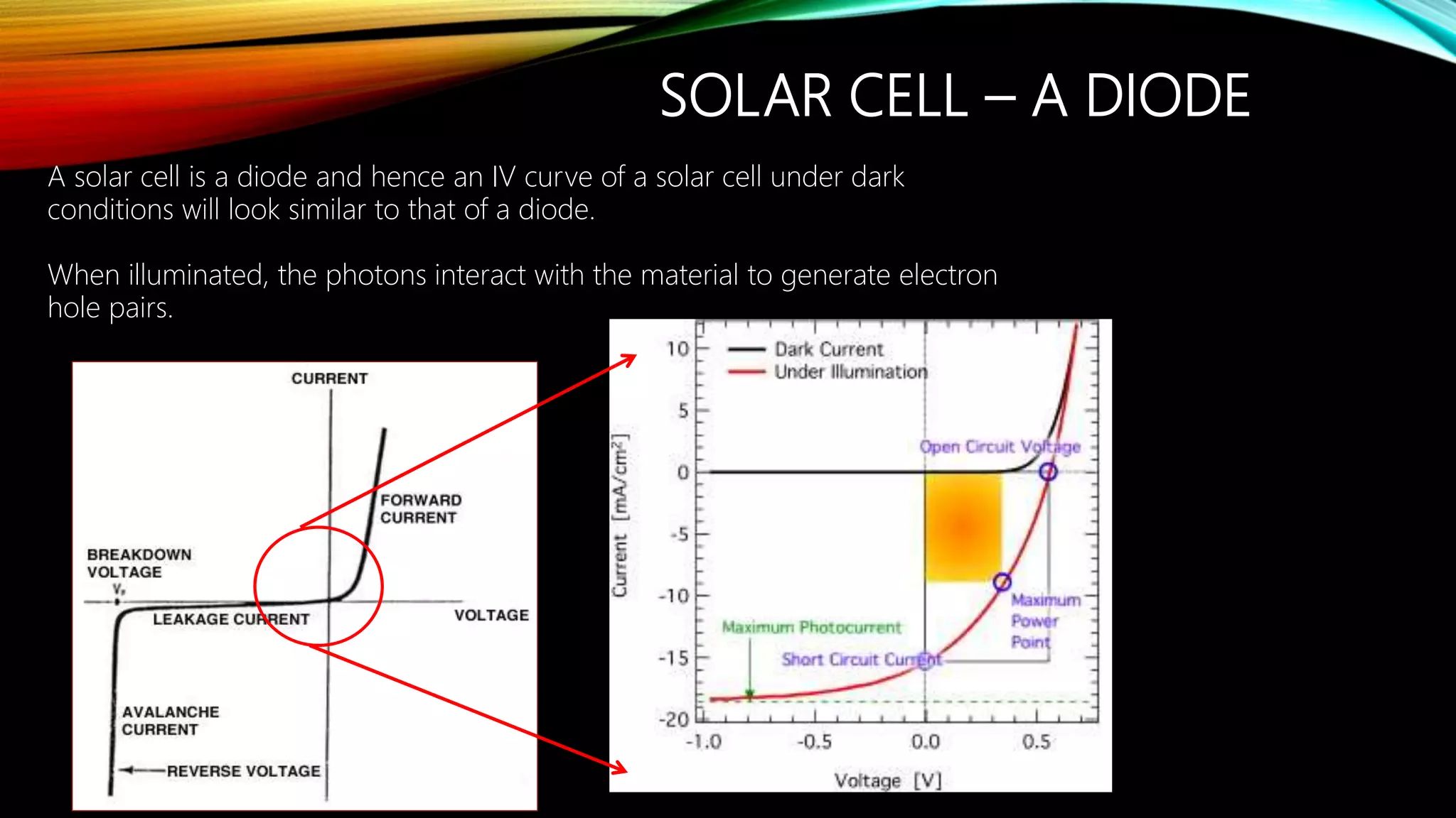
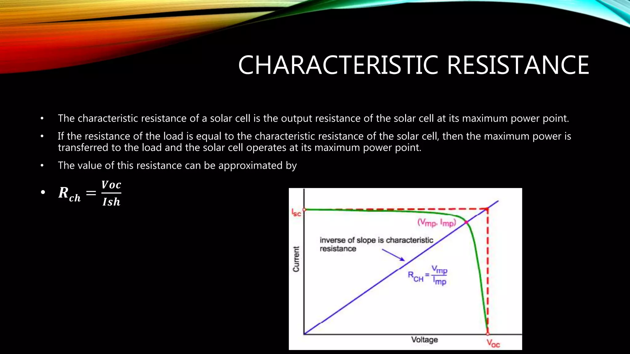
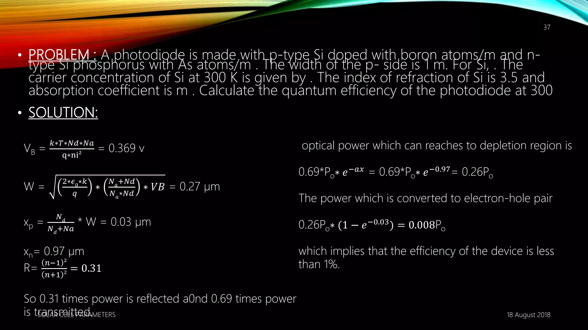
SOLAR CELL CHARACTERISTICS
• By 17MSE004
17MSE007
17MSE009
17MSE014
M.TECH ENERGY SYSTEMS
PANDIT DEENDAYAL PETROLEUM UNIVERSITY
18 August 2018SOLAR CELL PARAMETERS
1
Basic Structure of a Solar Cell
KEY PARAMETERS
• Open Circuit Voltage Voc
• Short Circuit Current Isc
• Shunt Resistance
• Series Resistance
• Internal quantum efficiency
• External quantum efficiency
SOLAR CELL – A DIODE
A solar cell is a diode and hence an IV curve of a solar cell under dark
conditions will look similar to that of a diode.
When illuminated, the photons interact with the material to generate electron
hole pairs.
STANDARD TEST CONDITIONS
• Temperature = 25 ˚C
• Important device characteristics can be obtained from the I-V
measurements.
SOLAR SIMULATOR
OPEN CIRCUIT VOLTAGE VOC (V)
• In an ideal solar cell, Voc is independent of the illumination intensity.
• Maximum voltage generated across the terminals of a solar cell when they
are kept open i.e. I=0
• The open circuit voltage depends on the light generated current and the
reverse saturation current
• Material having larger band gap have higher Voc .The band gap of silicon
is 1.1 eV. Therefore maximum possible Voc is 1.1 ev .
SHORT CIRCUIT CURRENT ISC
• Short circuit current is the maximum current produced by a solar cell when its
terminal are short circuited.
• When a photon is absorbed in a solar cells it generates an electron-hole pair which
is separated by a junction and then transported to the external circuit.
• For maximum short circuit current, we have to assume that there is no
recombination in the material .
• A photon is required to possess energy higher than the band gap energy of the
material in order to be absorbed.
• A material with a large band gap will absorb less number of photons as compared to
the material with low band gap.
• Therefore short circuit current will increase with decrease in the band gap.
MAXIMUM POWER
• Draw a rectangle with the
origin, VOC and ISC as the 3
corners. The 4th corner will
give the maximum
theoretical power, PT.
• From the origin, draw a line
passing through the
maximum theoretical power,
PT. This is the load line
The point where the load
line crosses the I-V curve is
the maximum power point,
PMAX for the solar cell, for a
given load, with maximum
current and maximum
voltage.
CALCULATE THE EFFICIENCY &PEAK POWER OF A SI
SOLAR CELLS OPERATING AT 27˚CWITH A SHORT
CIRCUIT CURRENT OF 2.2 A& OPERATING UNDER
STANDARD ILLUMINATION OF 1000W/M².THE AREA OF
SOLAR CELLS IS ABOUT 100 CM²
Solution
= 0.616 v
Consider the FF of the solar cells to be 0.75 or 75 %
The efficiency is given by
= 0.616*2.2*0.75/ 1000*100*10^-4
= 0.10164
= 10.16%
The peak power in this case is given as
Pmax = voc * Isc *FF
= 1.01 W
PARASITIC RESISTANCE
CHARACTERISTIC RESISTANCE
• The characteristic resistance of a solar cell is the output resistance of the solar cell at its maximum power point.
• If the resistance of the load is equal to the characteristic resistance of the solar cell, then the maximum power is
transferred to the load and the solar cell operates at its maximum power point.
• The value of this resistance can be approximated by
• 𝑹 𝒄𝒉 =
𝑽𝒐𝒄
𝑰𝒔𝒉
PARASITIC RESISTANCES
• Series resistance Rs of a PV module represents resistances in cell solder bonds,
emitter and base regions, cell metallization, cell interconnect Bus bars and
resistances in junction box terminations.
• The shunt resistance, Rsh, represents any parallel high-conductivity paths (shunts)
across the solar cell p-n junction or on the cell edges . These are due to crystal
damage and impurities in and near the junction and give rise to the shunt current,
Ish.
• For a good Fill Factor we want Rs as low as possible and Rsh as high as possible.
SERIES RESISTANCE
• It is, therefore, evident that a small increase in Rs can be
detrimental to the performance of PV modules due to
the power loss. Dark current–voltage (I–V) measurements
can be used to quantitatively evaluate increases in Rs.
These measurements are also sensitive to changes in
module shunt resistance and other cell parameters.
• 𝑃′ 𝑀𝑃 = 𝑃 𝑀𝑃 1 − 𝑟𝑠
• Also, since the open circuit voltage and short circuit
current are not affected:
• 𝐹𝐹′
= 𝐹𝐹(1 − 𝑟𝑠)
• A straight-forward method of estimating the series
resistance from a solar cell is to find the slope of the IV
curve at the open-circuit voltage point
EFFECT OF SERIES RESISTANCE
SHUNT RESISTANCE
EFFECT OF SHUNT RESISTANCE
• Low shunt resistance causes power losses in solar cells by providing an alternate current
path for the light-generated current. Such a diversion reduces the amount of current
flowing through the solar cell junction and reduces the voltage from the solar cell.
• The effect of a shunt resistance is particularly severe at low light levels, since there will be
less light-generated current.at lower voltages where the effective resistance of the solar cell
is high, the impact of a resistance in parallel is large.
• 𝑃′ 𝑀𝑃 = 𝑃 𝑀𝑃 1 −
1
𝑟 𝑠ℎ
• Also, since the open circuit voltage and short circuit current are not affected:
• 𝐹𝐹′ = 𝐹𝐹(1 −
1
𝑟 𝑠ℎ
)
IMPACT OF SERIES AND SHUNT
RESISTANCES
• In the presence of both series and shunt resistances, the I-V curve of the solar cell
is given by;
• 𝐼 = 𝐼𝐿 − 𝐼 𝑜 exp
𝑞 𝑉+𝐼𝑅𝑠
𝑛𝑘𝑡
−
𝑉+𝐼𝑅𝑠
𝑅𝑠ℎ
• The overall fill factor FF is
• 𝐹𝐹′ = 𝐹𝐹(1 − 𝑟𝑠)(1 −
1
𝑟 𝑠ℎ
)
TWO DIODE MODEL
• From Fig it is clear that the shunt current, Ish, detracts from the current output and the potential
drop across Rs reduces the voltage output of the solar cell. The influence of Rs and Rsh on the I–V
characteristics can be determined by using
• Eq.
• 𝐼 = 𝐼𝐿 − 𝐼 𝑜 exp
𝑞 𝑉+𝐼𝑅𝑠
𝑛𝑘𝑡
−
𝑉+𝐼𝑅𝑠
𝑅𝑠ℎ
• In this study, all simulated I–V characteristics were generated using PV simulation software, PVSIM
This software uses the two-diode model and calculates I–V characteristics based on typical solar
cell parameters. The simulations were done using 1000 W/m2 irradiance and 25 C cell
temperature.
MEASURING PARASITIC
RESISTANCES
• A straight-forward method of estimating the series resistance from a solar cell is to
find the slope of the IV curve at the open-circuit voltage point
• A straight-forward method of estimating the shunt resistance from a solar cell is to
find the slope of the IV curve at the short circuit current point
• This, however, does not represent the true values and only gives a rough indication
of respective resistance values.
MEASURING PARASITIC
RESISTANCES PRACTICALLY
• Rs can be determined by measuring I–V curves at different light intensities from a line
drawn through points corresponding to a fixed current below the respective Isc on each
curve. Rs is then obtained from the slope of this curve, with Rs = DV/DI. This result
generally gives good results and is independent of Io, n and Rsh
• The system used is a non-intrusive technique that measures the individual cell shunt
resistances of cells in encapsulated modules
• In this system, a variable power supply is used to bring the illuminated module to zero bias.
At this condition, a small AC signal is applied to the module, the only conduction path
being through the shunt resistances of the individual cells. The cells are then sequentially
shaded each time ensuring the DC supply remains equal to the Voc of the module. The
magnitude of the AC signal when the cells are sequentially shaded is directly proportional
to the conductance of the module in the dark i.e., the shunt current.
QUANTUM EFFICIENCY
OF SOLAR CELL
WHAT IS QUANTUM EFFICIENCY?
•
𝑁𝑢𝑚𝑏𝑒𝑟 𝑜𝑓 𝑐𝑎𝑟𝑟𝑖𝑒𝑟𝑠 𝑐𝑜𝑙𝑙𝑒𝑐𝑡𝑒𝑑 𝑏𝑦 𝑠𝑜𝑙𝑎𝑟 𝑐𝑒𝑙𝑙
𝑁𝑢𝑚𝑏𝑒𝑟 𝑜𝑓 𝑝ℎ𝑜𝑡𝑜𝑛𝑠 𝑜𝑓 𝑎 𝑔𝑖𝑣𝑒𝑛 𝑒𝑛𝑒𝑟𝑔𝑦 𝑖𝑛𝑐𝑖𝑑𝑒𝑛𝑡 𝑜𝑛 𝑠𝑜𝑙𝑎𝑟 𝑐𝑒𝑙𝑙
• Function of Wavelength(λ) or Energy(E).
• All photons of certain wavelength are absorbed → efficiency is
unity of that wavelength.
• For energy below wavelength → zero.
18 August 2018SOLAR CELL PARAMETERS
24
QUANTUM EFFICIENCY
External Quantum
Efficiency(EQE)
• EQE =
𝐸𝑙𝑒𝑐𝑡𝑟𝑜𝑛𝑠 𝑠𝑒𝑐
𝑃ℎ𝑜𝑡𝑜𝑛𝑠 𝑠𝑒𝑐
=
𝐶𝑢𝑟𝑟𝑒𝑛𝑡/𝑐ℎ𝑎𝑟𝑔𝑒 𝑜𝑓 𝑜𝑛𝑒 𝑒𝑙𝑒𝑐𝑡𝑟𝑜𝑛
𝑡𝑜𝑡𝑎𝑙 𝑝𝑜𝑤𝑒𝑟 𝑜𝑓 𝑝ℎ𝑜𝑡𝑜𝑛𝑠/𝑒𝑛𝑒𝑟𝑔𝑦 𝑜𝑓 𝑜𝑛𝑒 𝑝ℎ𝑜𝑡𝑜𝑛
• Effect of optical losses
→ Transmission
→ Reflection
Internal Quantum
Efficiency(IQE)
• IQE =
𝐸𝑙𝑒𝑐𝑡𝑟𝑜𝑛𝑠 𝑠𝑒𝑐
𝐴𝑏𝑠𝑜𝑟𝑏𝑒𝑑 𝑃ℎ𝑜𝑡𝑜𝑛𝑠 𝑠𝑒𝑐
=
𝐸𝑄𝐸
1−𝑅𝑒𝑓𝑙𝑒𝑐𝑡𝑖𝑜𝑛
• Effect of collection probability.
→ charge recombination
18 August 2018SOLAR CELL PARAMETERS
25
QUANTUM EFFICIENCY
External Quantum
Efficiency(EQE)
• By surface texturing this can be
improved.
• For organic solar cells efficiency is high.
Internal Quantum
Efficiency(IQE)
• after optical losses, absorbed photons
which can generate collectable carriers.
18 August 2018SOLAR CELL PARAMETERS
26
18 August 2018SOLAR CELL PARAMETERS
27
• Ideally square
shape.
• Reduced due to
 recombination
effects
 Collection
probability
In blue portion
→ front surface recombination affects the efficiency.
→ due to surface passivation absorption of light is high.
 In green portion
→ absorption in bulk of solar cell.
→ low diffusion length will affect the collection probability
 Can be viewed as the collection probability due to generation profile
of single wavelength, integrated over device thickness and
normalized to incident number of photons.
18 August 2018
28
QUANTUM EFFICIENCY
•
𝑁𝑢𝑚𝑏𝑒𝑟 𝑜𝑓 𝑒𝑙𝑒𝑐𝑡𝑟𝑜𝑛𝑠 𝑝𝑒𝑟 𝑠𝑒𝑐𝑜𝑛𝑑 𝑖𝑛 𝑡ℎ𝑒 𝑜𝑢𝑡𝑝𝑢𝑡 𝑐𝑢𝑟𝑟𝑒𝑛𝑡(𝑁𝑒)
𝑁𝑢𝑚𝑏𝑒𝑟 𝑜𝑓 𝑝ℎ𝑜𝑡𝑜𝑛𝑠 𝑝𝑒𝑟 𝑠𝑒𝑐𝑜𝑛𝑑 𝑖𝑛 𝑡ℎ𝑒 𝑙𝑖𝑔ℎ𝑡 𝑡ℎ𝑎𝑡 ℎ𝑖𝑡𝑠 𝑡ℎ𝑒 𝑑𝑖𝑜𝑑𝑒(𝑁𝑝)
• QE =
𝑁 𝑒
𝑁 𝑝
• First step is to measuring a laser with both photo diode and a power meter to
obtain 𝑁 𝑒 and 𝑁 𝑝
• Two methods
1) Using Power Meter
2) Using Radiation Pressure
18 August 2018SOLAR CELL PARAMETERS
29
USING POWER METER
• Aligned through the
Faraday isolator
• HWP change the amounts
of light being transmitted
and reflected by the PBS.
• Using HWP power of the
reflected light coming from
the PBS can be adjusted.
• aligned onto a photo diode
or power meter to be
measured.
18 August 2018SOLAR CELL PARAMETERS
30
18 August 2018SOLAR CELL PARAMETERS
31
• First step required was to measure the photo diode's output
without being exposed to any laser light → Vdark
• Then the laser light being reflected by both polarizing beam splitters is aligned
onto the photo diode
• With the help of HWP and PBS → power is minimized.
• At this minimized power voltage is measured.→ Vmeasured
• The power meter is inserted directly in front of the photo diode to measure
the power of the laser at the same point.
• Then HWP and PBS adjust to increase the power and readings are taken.
• Then efficiency is calculated at each power level.
• Until the saturation voltage of photo diode is reached.
18 August 2018SOLAR CELL PARAMETERS
32
I =
V Measured−V Dark
𝑅
Ne=
𝐼
𝑞
Np=
𝑃
ℎ∗𝑣
P = power
v = frequency
h = plank’s constant.
USING RADIATION PRESSURE
18 August 2018SOLAR CELL PARAMETERS
33
18 August 2018SOLAR CELL PARAMETERS
34
• Aligned through the Faraday isolator
• HWP change the amounts of light being transmitted and reflected
by the PBS.
• Using HWP power of the reflected light coming from the PBS can be
adjusted.
• Several focusing lenses were also placed to control the size of the
laser beam.
• Another component of interest is the 90 % beam splitter used to
direct the beam toward the interferometer.
• This splitter allows 10 % of incident light to be transmitted.
• 10 % for symmetric port
• 90 % towards the vacuum chamber in order to reduced the noise.
18 August 2018SOLAR CELL PARAMETERS
35
I =
V Measured−V Dark
𝑅
Ne=
𝐼
𝑞
F =
N p∗2∗h∗ν
𝑐
F = m∗ω2∗X
dX=
λ
2∗π∗V0
* dV PD
V0= Vmax- Vmin
P = power
v = frequency
h = plank’s constant
Michelson interferometer
SPECTRAL RESPONSIVITY(Rλ)
• How much current comes out per incoming photon of given energy and
wavelength.
• Unit of Rλ =
𝑎𝑚𝑝𝑒𝑟𝑒𝑠
𝑤𝑎𝑡𝑡
• With the help of spectral responsivity we can find quantum efficiency of solar cell.
• For that,
η =
Rλ
λ
×
ℎ𝑐
𝑒
≈
Rλ
λ
× (1240 W*nm/A)
18 August 2018SOLAR CELL PARAMETERS
36
• PROBLEM : A photodiode is made with p-type Si doped with boron atoms/m and n-
type Si phosphorus with As atoms/m . The width of the p- side is 1 m. For Si, . The
carrier concentration of Si at 300 K is given by . The index of refraction of Si is 3.5 and
absorption coefficient is m . Calculate the quantum efficiency of the photodiode at 300
• SOLUTION:
18 August 2018SOLAR CELL PARAMETERS
37
VB =
𝑘∗𝑇∗𝑁𝑑∗𝑁𝑎
q∗ni2 = 0.369 v
W =
2∗𝜖0
∗𝑘
𝑞
∗
𝑁 𝑎
+𝑁𝑑
𝑁 𝑎
∗𝑁𝑑
∗ 𝑉𝐵 = 0.27 µm
xp =
𝑁 𝑑
𝑁 𝑑
+𝑁𝑎
* W = 0.03 µm
xn= 0.97 µm
R=
𝑛−1 2
𝑛+1 2 = 0.31
So 0.31 times power is reflected a0nd 0.69 times power
is transmitted.
optical power which can reaches to depletion region is
0.69*Po∗ 𝑒−𝑎𝑥
= 0.69*Po∗ 𝑒−0.97
= 0.26Po
The power which is converted to electron-hole pair
0.26Po∗ (1 − 𝑒−0.03
) = 0.008Po
which implies that the efficiency of the device is less
than 1%.
THANK YOU
18 August 2018SOLAR CELL PARAMETERS
38

solar cell characteristics

  • 1.
    SOLAR CELL CHARACTERISTICS •By 17MSE004 17MSE007 17MSE009 17MSE014 M.TECH ENERGY SYSTEMS PANDIT DEENDAYAL PETROLEUM UNIVERSITY 18 August 2018SOLAR CELL PARAMETERS 1
  • 2.
    Basic Structure ofa Solar Cell
  • 3.
    KEY PARAMETERS • OpenCircuit Voltage Voc • Short Circuit Current Isc • Shunt Resistance • Series Resistance • Internal quantum efficiency • External quantum efficiency
  • 4.
    SOLAR CELL –A DIODE A solar cell is a diode and hence an IV curve of a solar cell under dark conditions will look similar to that of a diode. When illuminated, the photons interact with the material to generate electron hole pairs.
  • 5.
    STANDARD TEST CONDITIONS •Temperature = 25 ˚C • Important device characteristics can be obtained from the I-V measurements.
  • 6.
  • 7.
    OPEN CIRCUIT VOLTAGEVOC (V) • In an ideal solar cell, Voc is independent of the illumination intensity. • Maximum voltage generated across the terminals of a solar cell when they are kept open i.e. I=0 • The open circuit voltage depends on the light generated current and the reverse saturation current • Material having larger band gap have higher Voc .The band gap of silicon is 1.1 eV. Therefore maximum possible Voc is 1.1 ev .
  • 8.
    SHORT CIRCUIT CURRENTISC • Short circuit current is the maximum current produced by a solar cell when its terminal are short circuited. • When a photon is absorbed in a solar cells it generates an electron-hole pair which is separated by a junction and then transported to the external circuit. • For maximum short circuit current, we have to assume that there is no recombination in the material . • A photon is required to possess energy higher than the band gap energy of the material in order to be absorbed. • A material with a large band gap will absorb less number of photons as compared to the material with low band gap. • Therefore short circuit current will increase with decrease in the band gap.
  • 9.
    MAXIMUM POWER • Drawa rectangle with the origin, VOC and ISC as the 3 corners. The 4th corner will give the maximum theoretical power, PT. • From the origin, draw a line passing through the maximum theoretical power, PT. This is the load line The point where the load line crosses the I-V curve is the maximum power point, PMAX for the solar cell, for a given load, with maximum current and maximum voltage.
  • 10.
    CALCULATE THE EFFICIENCY&PEAK POWER OF A SI SOLAR CELLS OPERATING AT 27˚CWITH A SHORT CIRCUIT CURRENT OF 2.2 A& OPERATING UNDER STANDARD ILLUMINATION OF 1000W/M².THE AREA OF SOLAR CELLS IS ABOUT 100 CM² Solution = 0.616 v
  • 11.
    Consider the FFof the solar cells to be 0.75 or 75 % The efficiency is given by = 0.616*2.2*0.75/ 1000*100*10^-4 = 0.10164 = 10.16% The peak power in this case is given as Pmax = voc * Isc *FF = 1.01 W
  • 12.
  • 13.
    CHARACTERISTIC RESISTANCE • Thecharacteristic resistance of a solar cell is the output resistance of the solar cell at its maximum power point. • If the resistance of the load is equal to the characteristic resistance of the solar cell, then the maximum power is transferred to the load and the solar cell operates at its maximum power point. • The value of this resistance can be approximated by • 𝑹 𝒄𝒉 = 𝑽𝒐𝒄 𝑰𝒔𝒉
  • 14.
    PARASITIC RESISTANCES • Seriesresistance Rs of a PV module represents resistances in cell solder bonds, emitter and base regions, cell metallization, cell interconnect Bus bars and resistances in junction box terminations. • The shunt resistance, Rsh, represents any parallel high-conductivity paths (shunts) across the solar cell p-n junction or on the cell edges . These are due to crystal damage and impurities in and near the junction and give rise to the shunt current, Ish. • For a good Fill Factor we want Rs as low as possible and Rsh as high as possible.
  • 15.
  • 16.
    • It is,therefore, evident that a small increase in Rs can be detrimental to the performance of PV modules due to the power loss. Dark current–voltage (I–V) measurements can be used to quantitatively evaluate increases in Rs. These measurements are also sensitive to changes in module shunt resistance and other cell parameters. • 𝑃′ 𝑀𝑃 = 𝑃 𝑀𝑃 1 − 𝑟𝑠 • Also, since the open circuit voltage and short circuit current are not affected: • 𝐹𝐹′ = 𝐹𝐹(1 − 𝑟𝑠) • A straight-forward method of estimating the series resistance from a solar cell is to find the slope of the IV curve at the open-circuit voltage point EFFECT OF SERIES RESISTANCE
  • 17.
  • 18.
    EFFECT OF SHUNTRESISTANCE • Low shunt resistance causes power losses in solar cells by providing an alternate current path for the light-generated current. Such a diversion reduces the amount of current flowing through the solar cell junction and reduces the voltage from the solar cell. • The effect of a shunt resistance is particularly severe at low light levels, since there will be less light-generated current.at lower voltages where the effective resistance of the solar cell is high, the impact of a resistance in parallel is large. • 𝑃′ 𝑀𝑃 = 𝑃 𝑀𝑃 1 − 1 𝑟 𝑠ℎ • Also, since the open circuit voltage and short circuit current are not affected: • 𝐹𝐹′ = 𝐹𝐹(1 − 1 𝑟 𝑠ℎ )
  • 19.
    IMPACT OF SERIESAND SHUNT RESISTANCES • In the presence of both series and shunt resistances, the I-V curve of the solar cell is given by; • 𝐼 = 𝐼𝐿 − 𝐼 𝑜 exp 𝑞 𝑉+𝐼𝑅𝑠 𝑛𝑘𝑡 − 𝑉+𝐼𝑅𝑠 𝑅𝑠ℎ • The overall fill factor FF is • 𝐹𝐹′ = 𝐹𝐹(1 − 𝑟𝑠)(1 − 1 𝑟 𝑠ℎ )
  • 20.
    TWO DIODE MODEL •From Fig it is clear that the shunt current, Ish, detracts from the current output and the potential drop across Rs reduces the voltage output of the solar cell. The influence of Rs and Rsh on the I–V characteristics can be determined by using • Eq. • 𝐼 = 𝐼𝐿 − 𝐼 𝑜 exp 𝑞 𝑉+𝐼𝑅𝑠 𝑛𝑘𝑡 − 𝑉+𝐼𝑅𝑠 𝑅𝑠ℎ • In this study, all simulated I–V characteristics were generated using PV simulation software, PVSIM This software uses the two-diode model and calculates I–V characteristics based on typical solar cell parameters. The simulations were done using 1000 W/m2 irradiance and 25 C cell temperature.
  • 21.
    MEASURING PARASITIC RESISTANCES • Astraight-forward method of estimating the series resistance from a solar cell is to find the slope of the IV curve at the open-circuit voltage point • A straight-forward method of estimating the shunt resistance from a solar cell is to find the slope of the IV curve at the short circuit current point • This, however, does not represent the true values and only gives a rough indication of respective resistance values.
  • 22.
    MEASURING PARASITIC RESISTANCES PRACTICALLY •Rs can be determined by measuring I–V curves at different light intensities from a line drawn through points corresponding to a fixed current below the respective Isc on each curve. Rs is then obtained from the slope of this curve, with Rs = DV/DI. This result generally gives good results and is independent of Io, n and Rsh • The system used is a non-intrusive technique that measures the individual cell shunt resistances of cells in encapsulated modules • In this system, a variable power supply is used to bring the illuminated module to zero bias. At this condition, a small AC signal is applied to the module, the only conduction path being through the shunt resistances of the individual cells. The cells are then sequentially shaded each time ensuring the DC supply remains equal to the Voc of the module. The magnitude of the AC signal when the cells are sequentially shaded is directly proportional to the conductance of the module in the dark i.e., the shunt current.
  • 23.
  • 24.
    WHAT IS QUANTUMEFFICIENCY? • 𝑁𝑢𝑚𝑏𝑒𝑟 𝑜𝑓 𝑐𝑎𝑟𝑟𝑖𝑒𝑟𝑠 𝑐𝑜𝑙𝑙𝑒𝑐𝑡𝑒𝑑 𝑏𝑦 𝑠𝑜𝑙𝑎𝑟 𝑐𝑒𝑙𝑙 𝑁𝑢𝑚𝑏𝑒𝑟 𝑜𝑓 𝑝ℎ𝑜𝑡𝑜𝑛𝑠 𝑜𝑓 𝑎 𝑔𝑖𝑣𝑒𝑛 𝑒𝑛𝑒𝑟𝑔𝑦 𝑖𝑛𝑐𝑖𝑑𝑒𝑛𝑡 𝑜𝑛 𝑠𝑜𝑙𝑎𝑟 𝑐𝑒𝑙𝑙 • Function of Wavelength(λ) or Energy(E). • All photons of certain wavelength are absorbed → efficiency is unity of that wavelength. • For energy below wavelength → zero. 18 August 2018SOLAR CELL PARAMETERS 24
  • 25.
    QUANTUM EFFICIENCY External Quantum Efficiency(EQE) •EQE = 𝐸𝑙𝑒𝑐𝑡𝑟𝑜𝑛𝑠 𝑠𝑒𝑐 𝑃ℎ𝑜𝑡𝑜𝑛𝑠 𝑠𝑒𝑐 = 𝐶𝑢𝑟𝑟𝑒𝑛𝑡/𝑐ℎ𝑎𝑟𝑔𝑒 𝑜𝑓 𝑜𝑛𝑒 𝑒𝑙𝑒𝑐𝑡𝑟𝑜𝑛 𝑡𝑜𝑡𝑎𝑙 𝑝𝑜𝑤𝑒𝑟 𝑜𝑓 𝑝ℎ𝑜𝑡𝑜𝑛𝑠/𝑒𝑛𝑒𝑟𝑔𝑦 𝑜𝑓 𝑜𝑛𝑒 𝑝ℎ𝑜𝑡𝑜𝑛 • Effect of optical losses → Transmission → Reflection Internal Quantum Efficiency(IQE) • IQE = 𝐸𝑙𝑒𝑐𝑡𝑟𝑜𝑛𝑠 𝑠𝑒𝑐 𝐴𝑏𝑠𝑜𝑟𝑏𝑒𝑑 𝑃ℎ𝑜𝑡𝑜𝑛𝑠 𝑠𝑒𝑐 = 𝐸𝑄𝐸 1−𝑅𝑒𝑓𝑙𝑒𝑐𝑡𝑖𝑜𝑛 • Effect of collection probability. → charge recombination 18 August 2018SOLAR CELL PARAMETERS 25
  • 26.
    QUANTUM EFFICIENCY External Quantum Efficiency(EQE) •By surface texturing this can be improved. • For organic solar cells efficiency is high. Internal Quantum Efficiency(IQE) • after optical losses, absorbed photons which can generate collectable carriers. 18 August 2018SOLAR CELL PARAMETERS 26
  • 27.
    18 August 2018SOLARCELL PARAMETERS 27 • Ideally square shape. • Reduced due to  recombination effects  Collection probability
  • 28.
    In blue portion →front surface recombination affects the efficiency. → due to surface passivation absorption of light is high.  In green portion → absorption in bulk of solar cell. → low diffusion length will affect the collection probability  Can be viewed as the collection probability due to generation profile of single wavelength, integrated over device thickness and normalized to incident number of photons. 18 August 2018 28
  • 29.
    QUANTUM EFFICIENCY • 𝑁𝑢𝑚𝑏𝑒𝑟 𝑜𝑓𝑒𝑙𝑒𝑐𝑡𝑟𝑜𝑛𝑠 𝑝𝑒𝑟 𝑠𝑒𝑐𝑜𝑛𝑑 𝑖𝑛 𝑡ℎ𝑒 𝑜𝑢𝑡𝑝𝑢𝑡 𝑐𝑢𝑟𝑟𝑒𝑛𝑡(𝑁𝑒) 𝑁𝑢𝑚𝑏𝑒𝑟 𝑜𝑓 𝑝ℎ𝑜𝑡𝑜𝑛𝑠 𝑝𝑒𝑟 𝑠𝑒𝑐𝑜𝑛𝑑 𝑖𝑛 𝑡ℎ𝑒 𝑙𝑖𝑔ℎ𝑡 𝑡ℎ𝑎𝑡 ℎ𝑖𝑡𝑠 𝑡ℎ𝑒 𝑑𝑖𝑜𝑑𝑒(𝑁𝑝) • QE = 𝑁 𝑒 𝑁 𝑝 • First step is to measuring a laser with both photo diode and a power meter to obtain 𝑁 𝑒 and 𝑁 𝑝 • Two methods 1) Using Power Meter 2) Using Radiation Pressure 18 August 2018SOLAR CELL PARAMETERS 29
  • 30.
    USING POWER METER •Aligned through the Faraday isolator • HWP change the amounts of light being transmitted and reflected by the PBS. • Using HWP power of the reflected light coming from the PBS can be adjusted. • aligned onto a photo diode or power meter to be measured. 18 August 2018SOLAR CELL PARAMETERS 30
  • 31.
    18 August 2018SOLARCELL PARAMETERS 31 • First step required was to measure the photo diode's output without being exposed to any laser light → Vdark • Then the laser light being reflected by both polarizing beam splitters is aligned onto the photo diode • With the help of HWP and PBS → power is minimized. • At this minimized power voltage is measured.→ Vmeasured • The power meter is inserted directly in front of the photo diode to measure the power of the laser at the same point. • Then HWP and PBS adjust to increase the power and readings are taken. • Then efficiency is calculated at each power level. • Until the saturation voltage of photo diode is reached.
  • 32.
    18 August 2018SOLARCELL PARAMETERS 32 I = V Measured−V Dark 𝑅 Ne= 𝐼 𝑞 Np= 𝑃 ℎ∗𝑣 P = power v = frequency h = plank’s constant.
  • 33.
    USING RADIATION PRESSURE 18August 2018SOLAR CELL PARAMETERS 33
  • 34.
    18 August 2018SOLARCELL PARAMETERS 34 • Aligned through the Faraday isolator • HWP change the amounts of light being transmitted and reflected by the PBS. • Using HWP power of the reflected light coming from the PBS can be adjusted. • Several focusing lenses were also placed to control the size of the laser beam. • Another component of interest is the 90 % beam splitter used to direct the beam toward the interferometer. • This splitter allows 10 % of incident light to be transmitted. • 10 % for symmetric port • 90 % towards the vacuum chamber in order to reduced the noise.
  • 35.
    18 August 2018SOLARCELL PARAMETERS 35 I = V Measured−V Dark 𝑅 Ne= 𝐼 𝑞 F = N p∗2∗h∗ν 𝑐 F = m∗ω2∗X dX= λ 2∗π∗V0 * dV PD V0= Vmax- Vmin P = power v = frequency h = plank’s constant Michelson interferometer
  • 36.
    SPECTRAL RESPONSIVITY(Rλ) • Howmuch current comes out per incoming photon of given energy and wavelength. • Unit of Rλ = 𝑎𝑚𝑝𝑒𝑟𝑒𝑠 𝑤𝑎𝑡𝑡 • With the help of spectral responsivity we can find quantum efficiency of solar cell. • For that, η = Rλ λ × ℎ𝑐 𝑒 ≈ Rλ λ × (1240 W*nm/A) 18 August 2018SOLAR CELL PARAMETERS 36
  • 37.
    • PROBLEM :A photodiode is made with p-type Si doped with boron atoms/m and n- type Si phosphorus with As atoms/m . The width of the p- side is 1 m. For Si, . The carrier concentration of Si at 300 K is given by . The index of refraction of Si is 3.5 and absorption coefficient is m . Calculate the quantum efficiency of the photodiode at 300 • SOLUTION: 18 August 2018SOLAR CELL PARAMETERS 37 VB = 𝑘∗𝑇∗𝑁𝑑∗𝑁𝑎 q∗ni2 = 0.369 v W = 2∗𝜖0 ∗𝑘 𝑞 ∗ 𝑁 𝑎 +𝑁𝑑 𝑁 𝑎 ∗𝑁𝑑 ∗ 𝑉𝐵 = 0.27 µm xp = 𝑁 𝑑 𝑁 𝑑 +𝑁𝑎 * W = 0.03 µm xn= 0.97 µm R= 𝑛−1 2 𝑛+1 2 = 0.31 So 0.31 times power is reflected a0nd 0.69 times power is transmitted. optical power which can reaches to depletion region is 0.69*Po∗ 𝑒−𝑎𝑥 = 0.69*Po∗ 𝑒−0.97 = 0.26Po The power which is converted to electron-hole pair 0.26Po∗ (1 − 𝑒−0.03 ) = 0.008Po which implies that the efficiency of the device is less than 1%.
  • 38.
    THANK YOU 18 August2018SOLAR CELL PARAMETERS 38