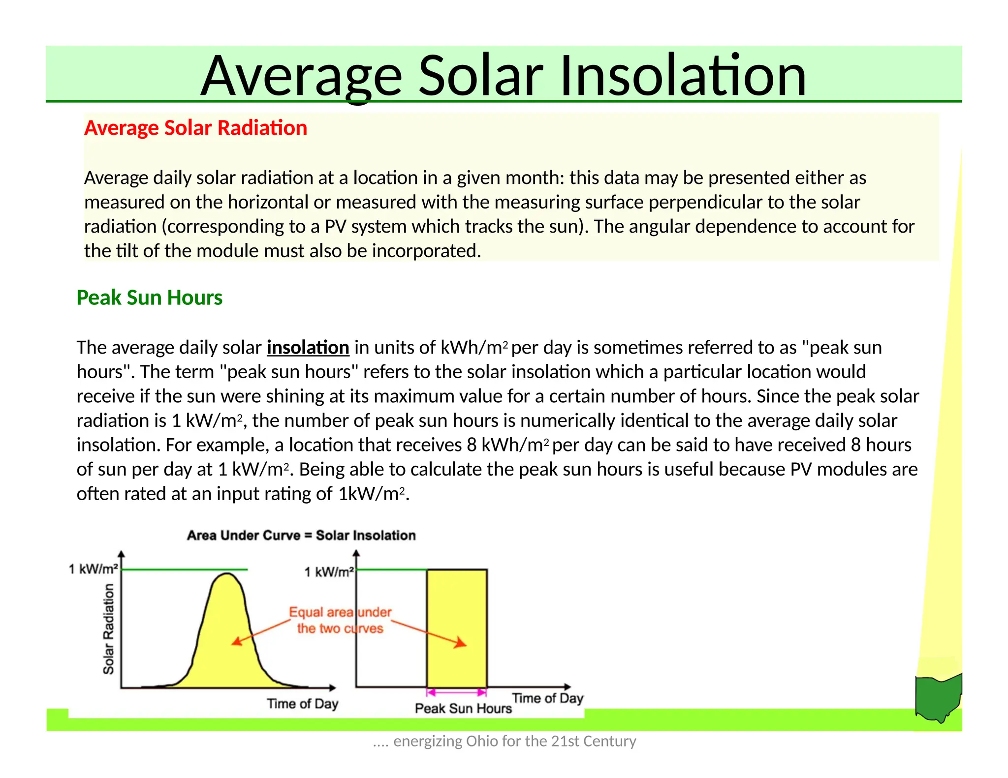
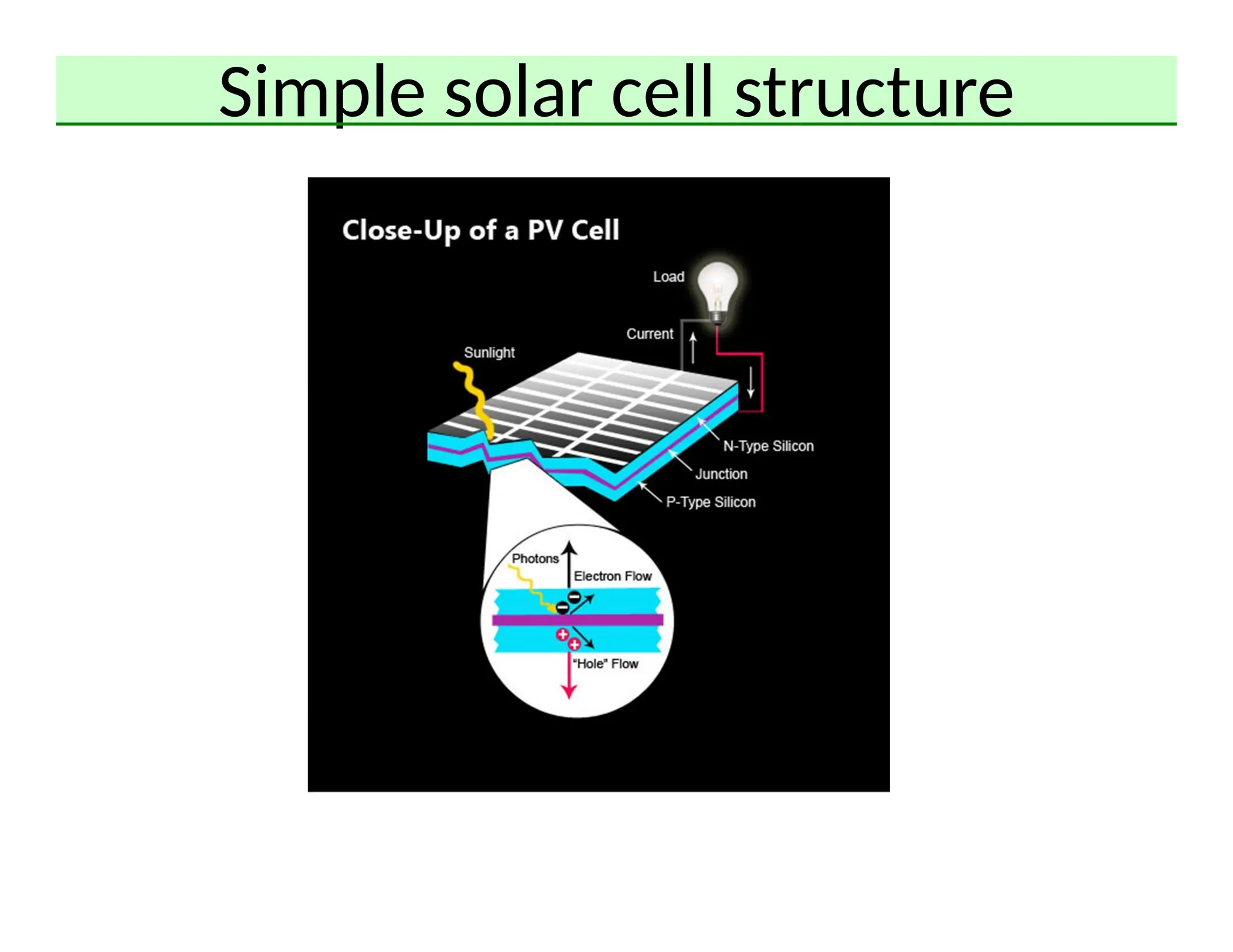
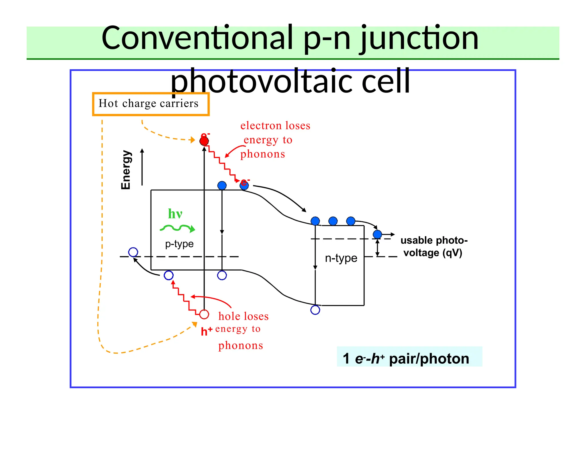
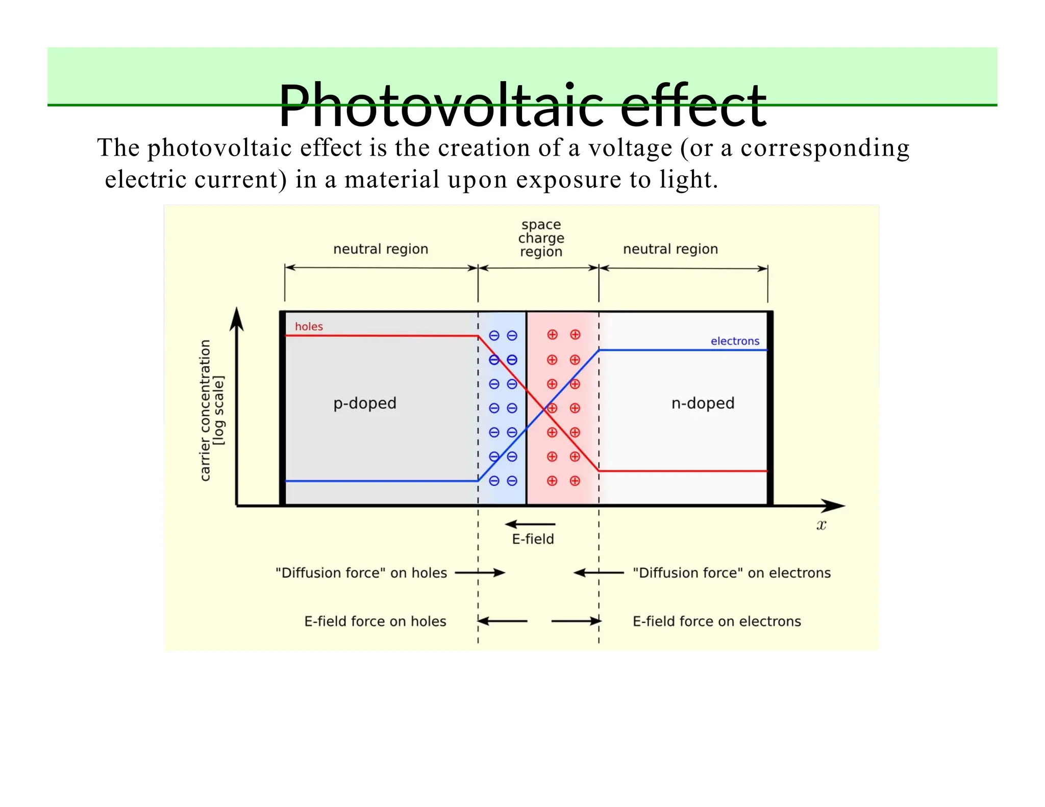
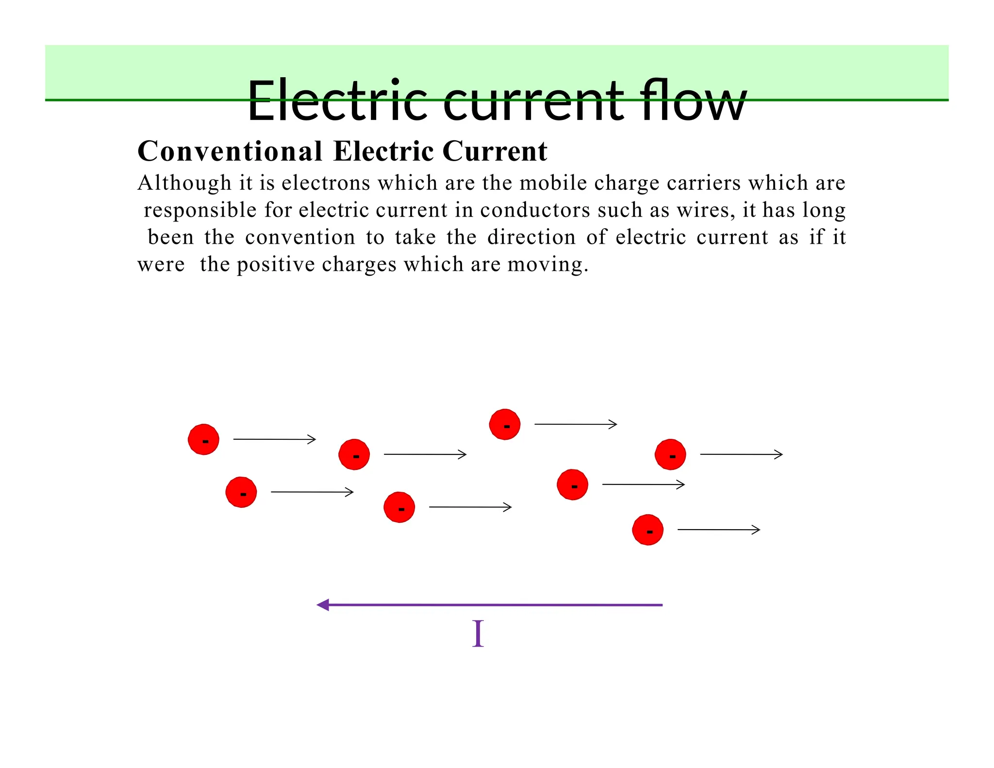
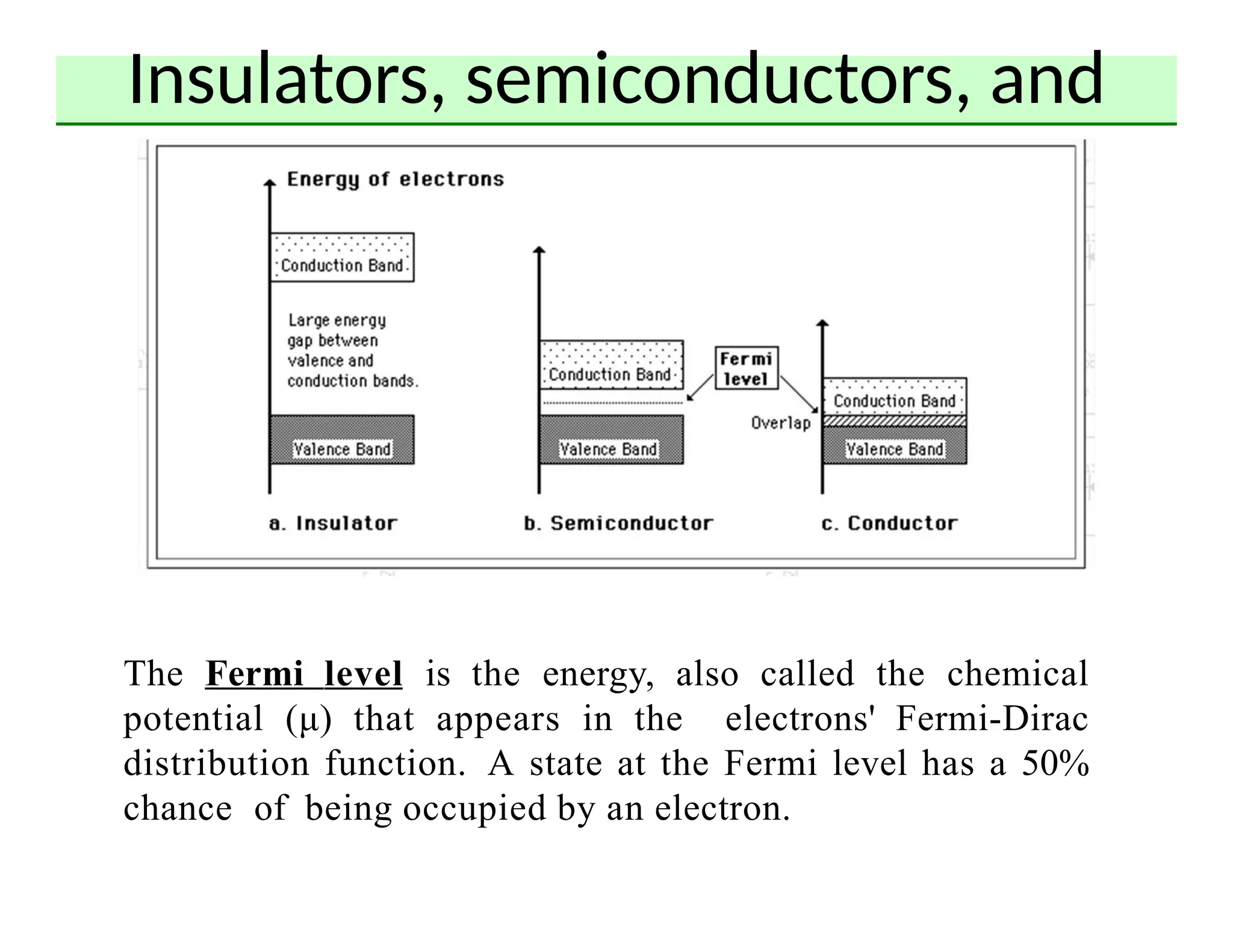
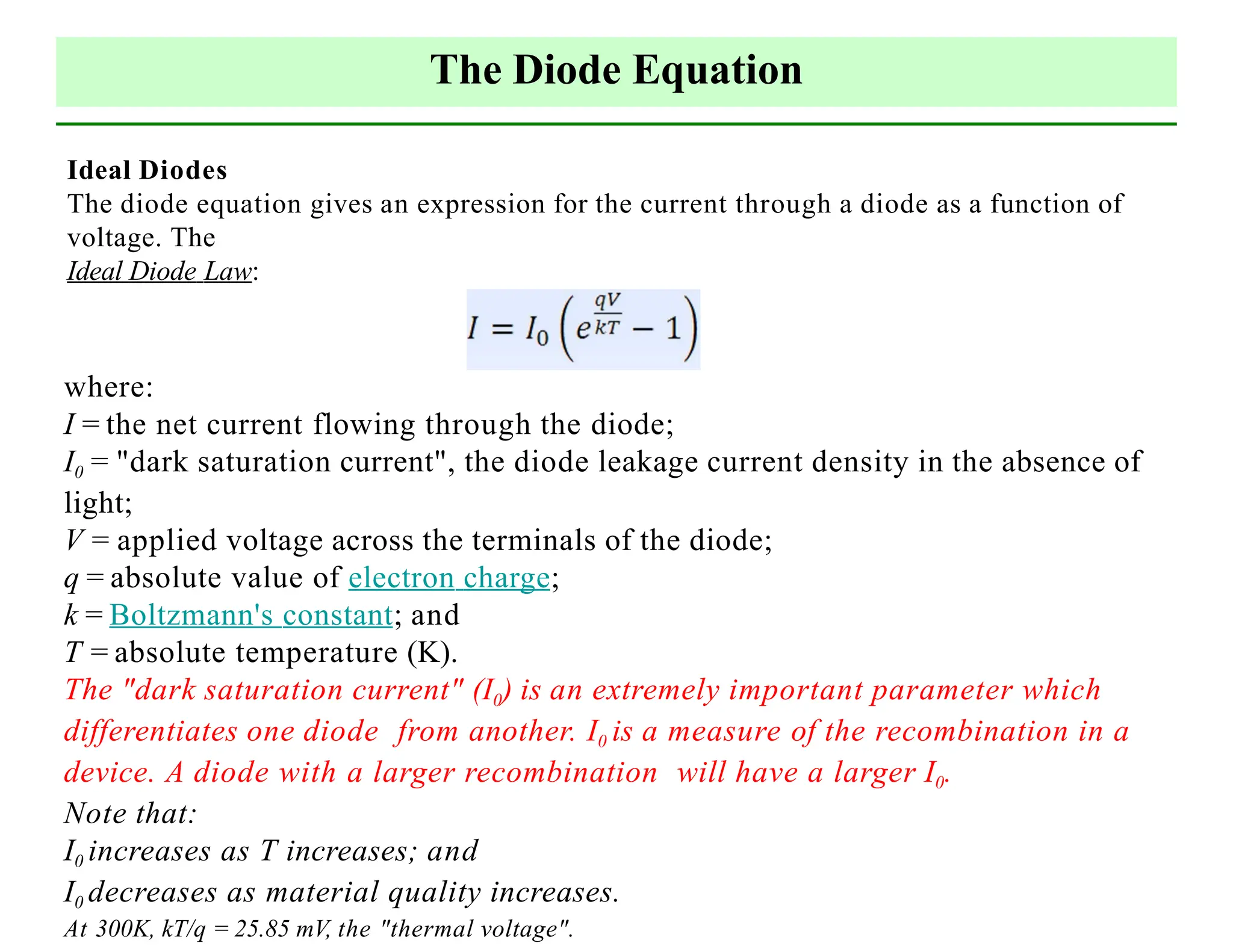
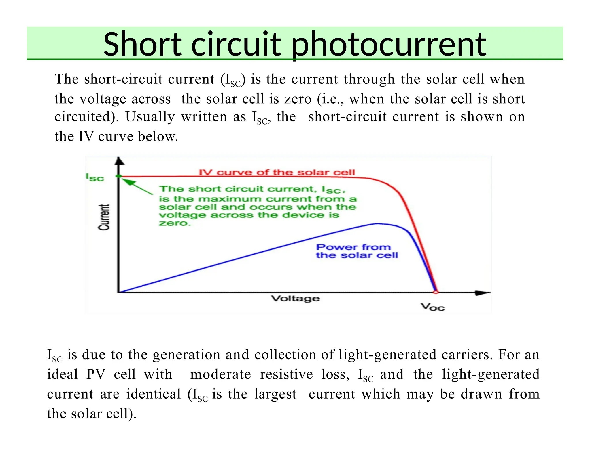
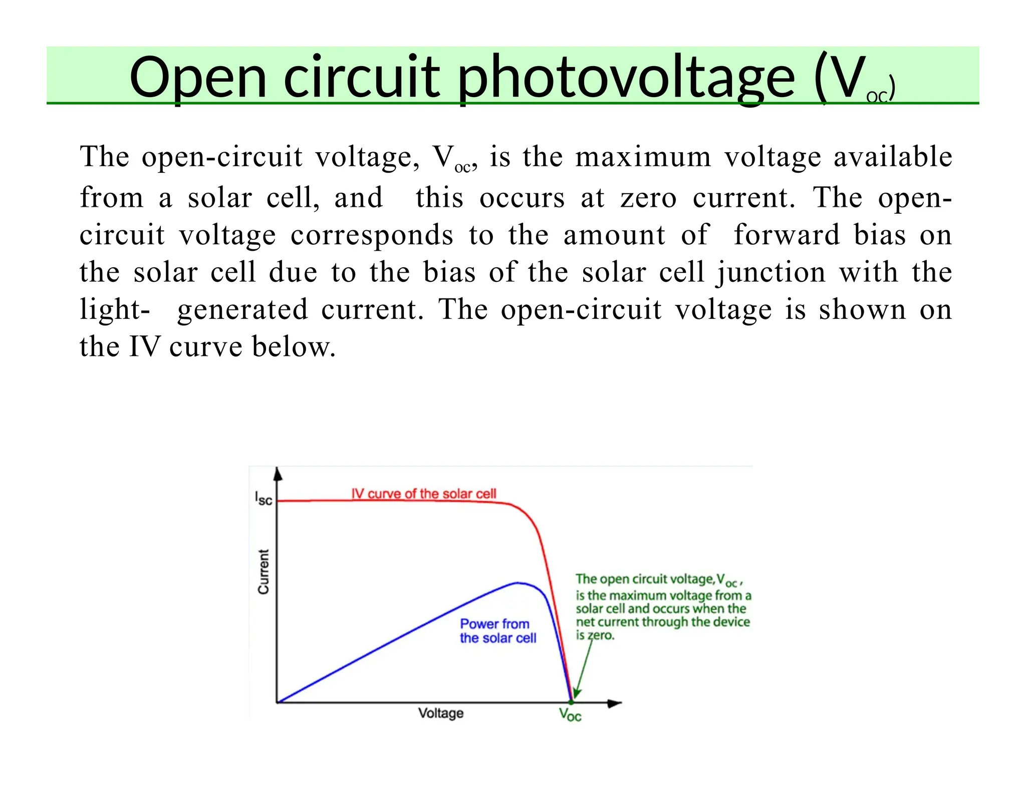
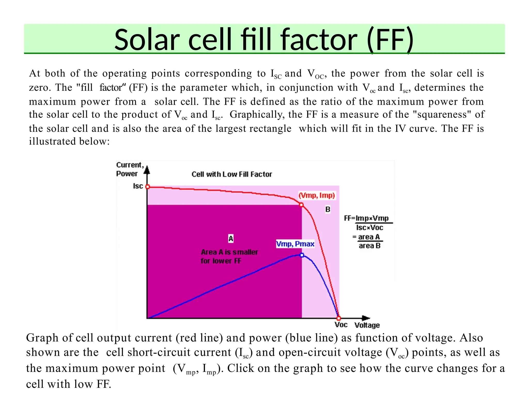
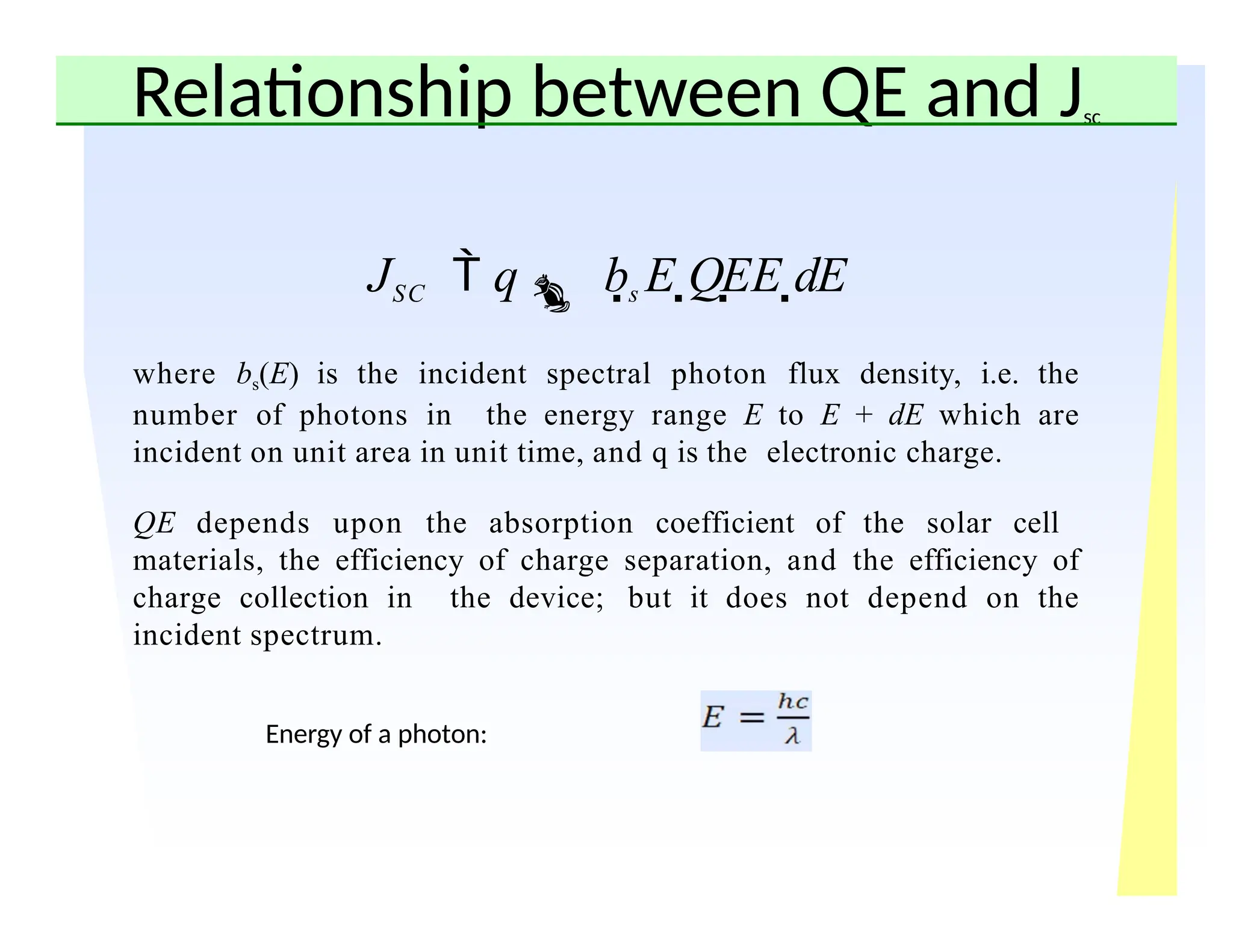
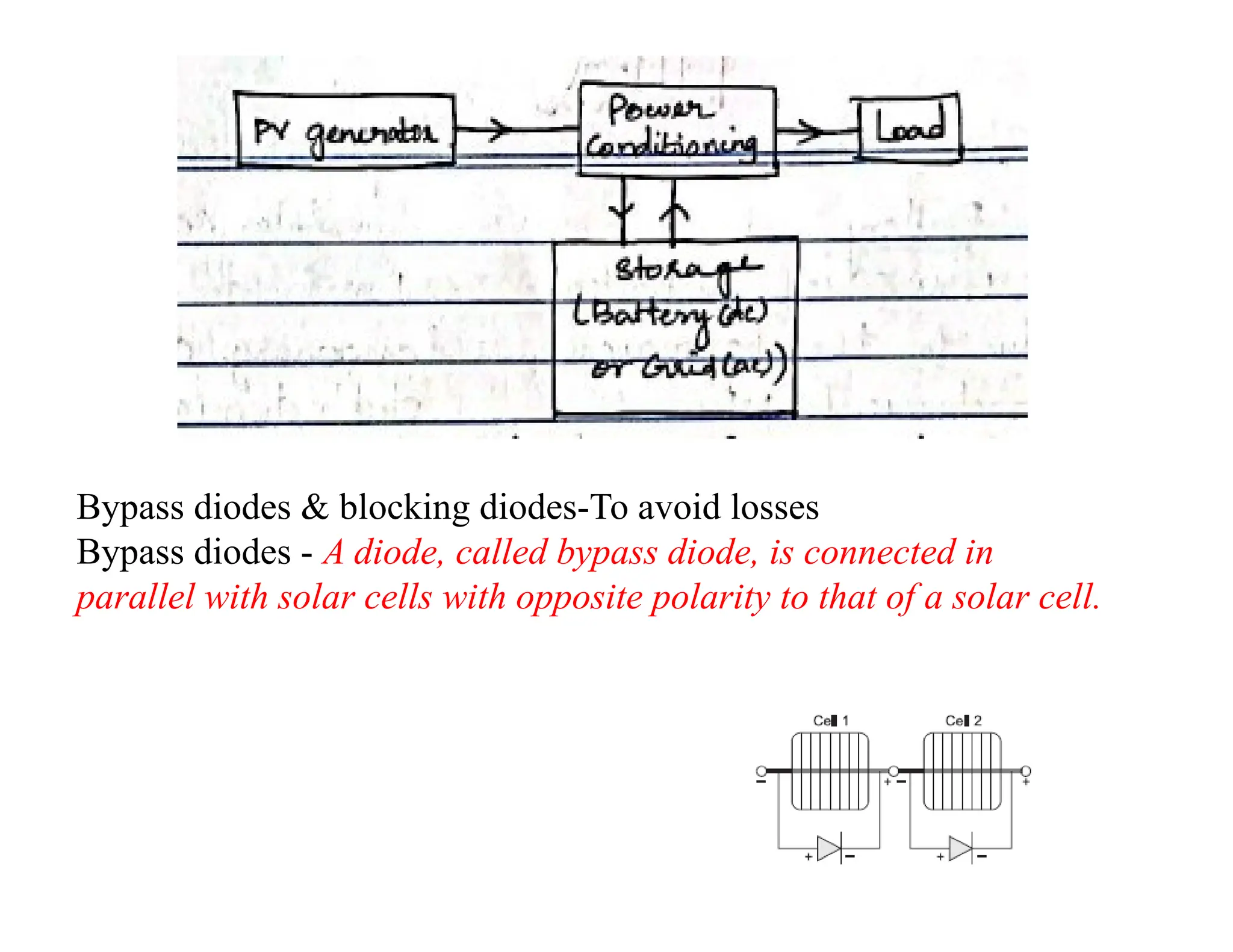
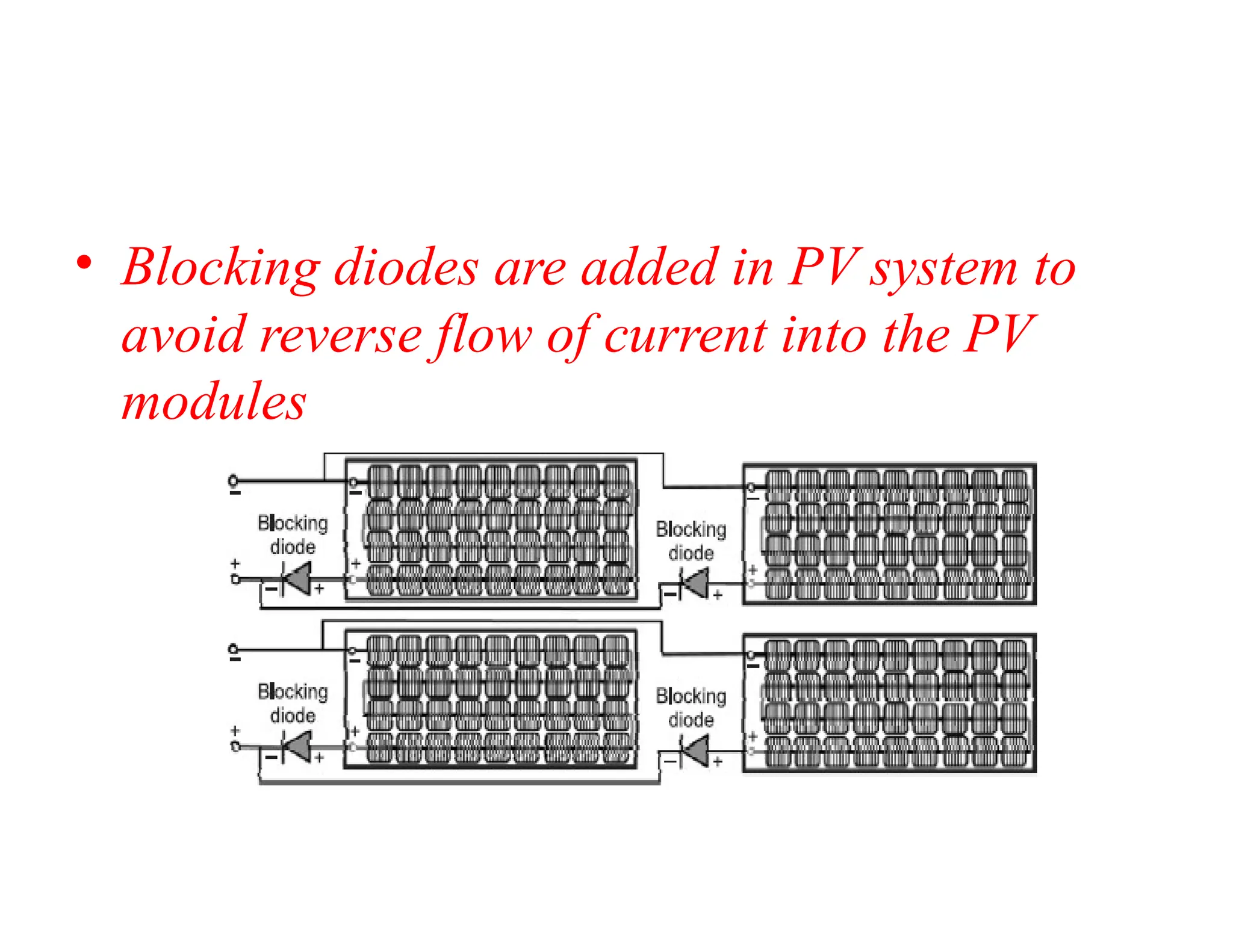
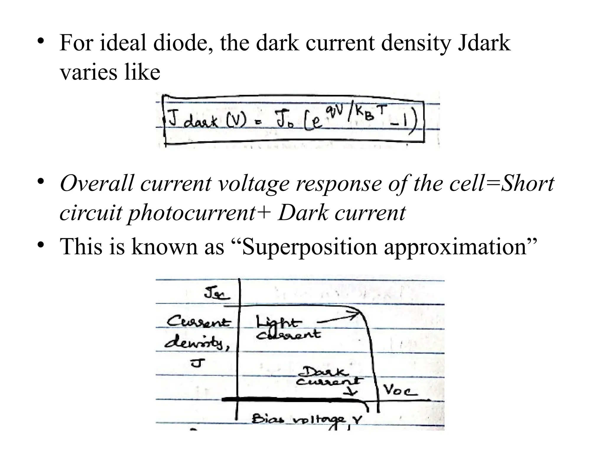
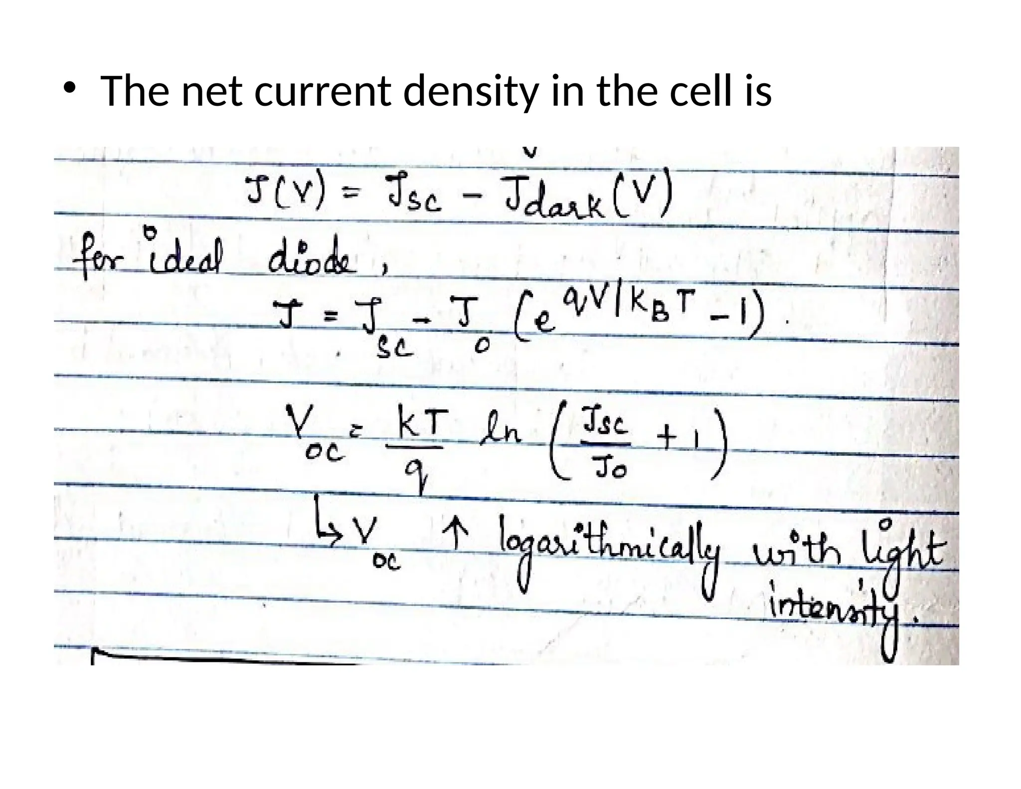
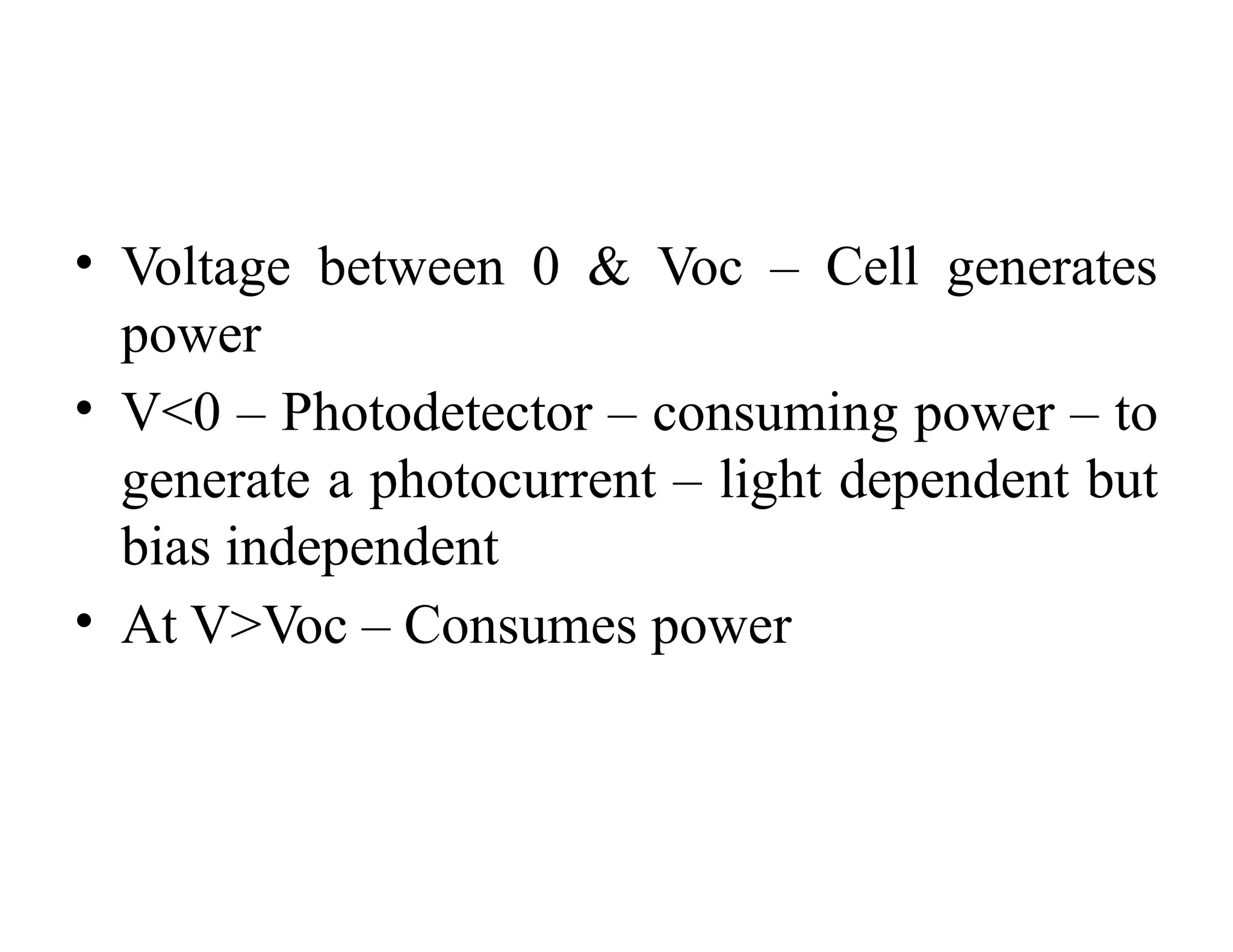
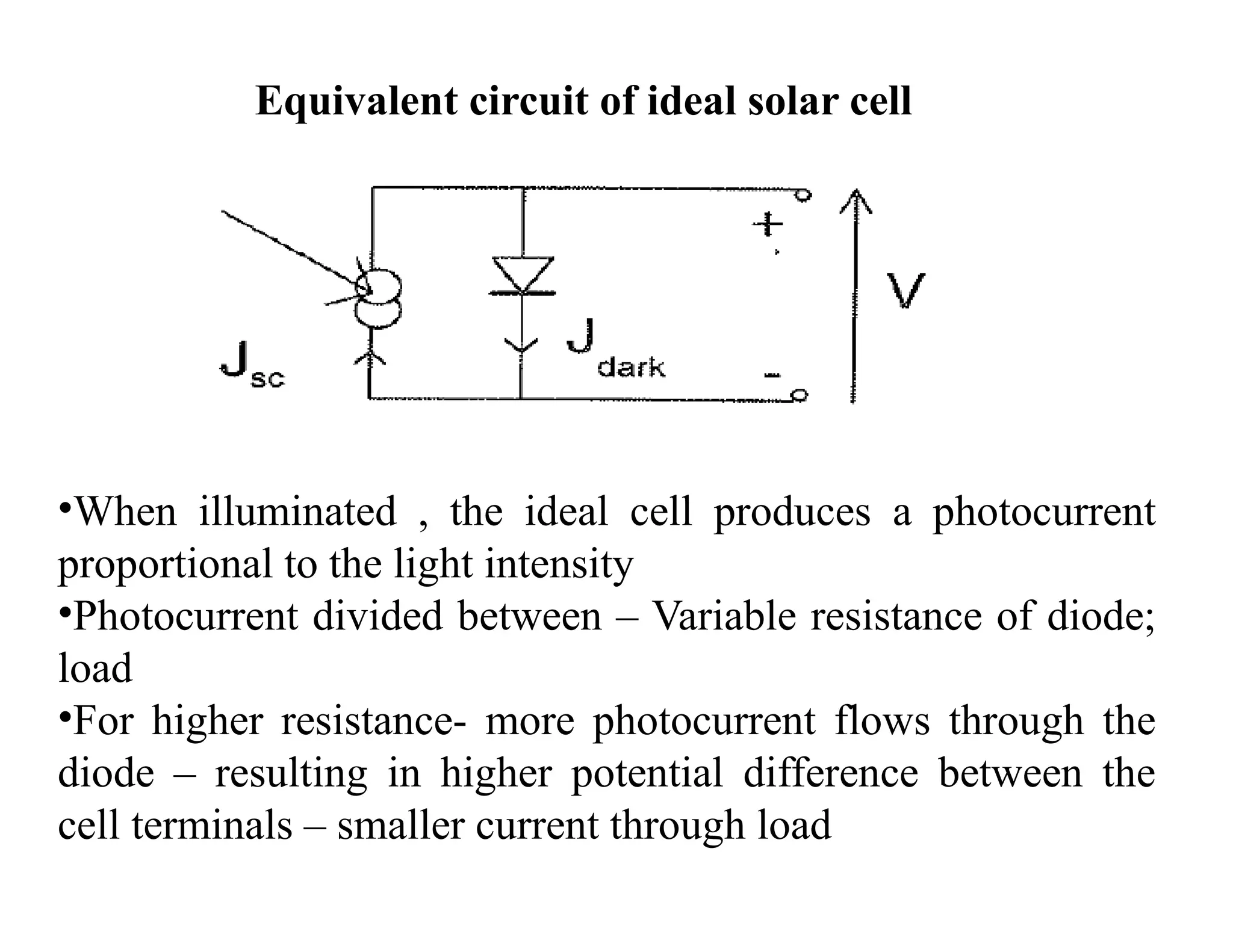
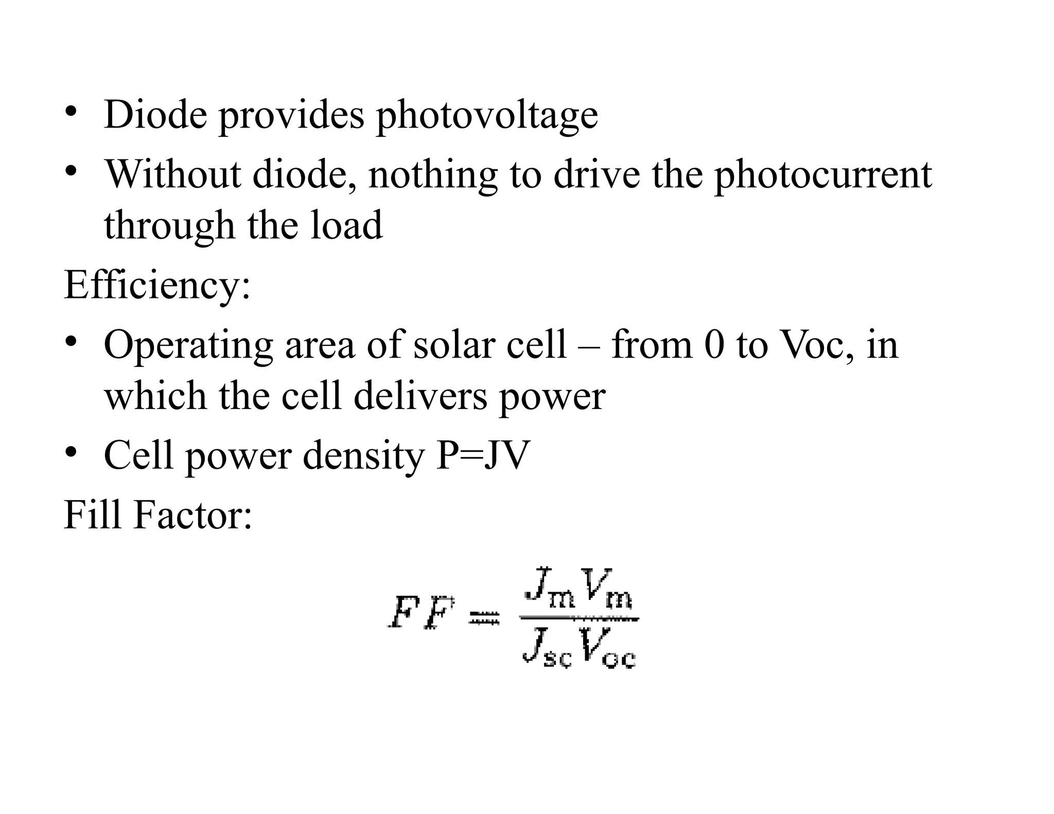
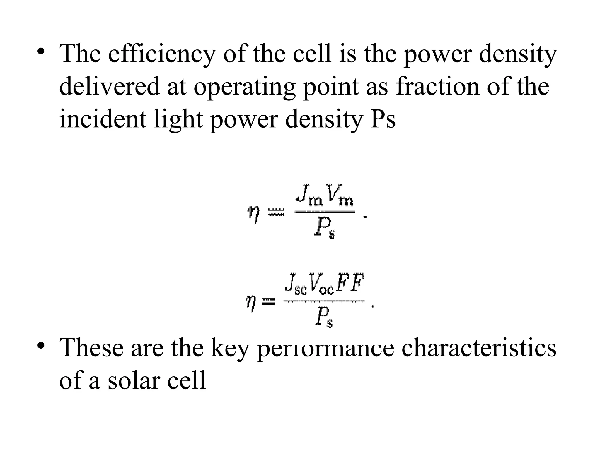
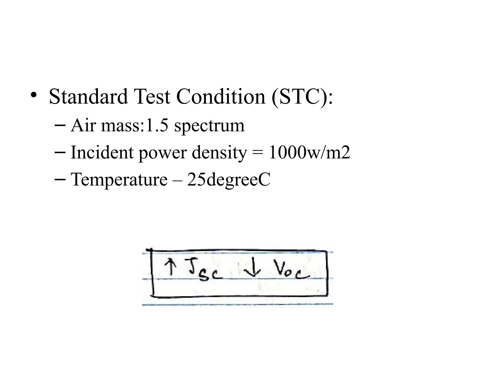
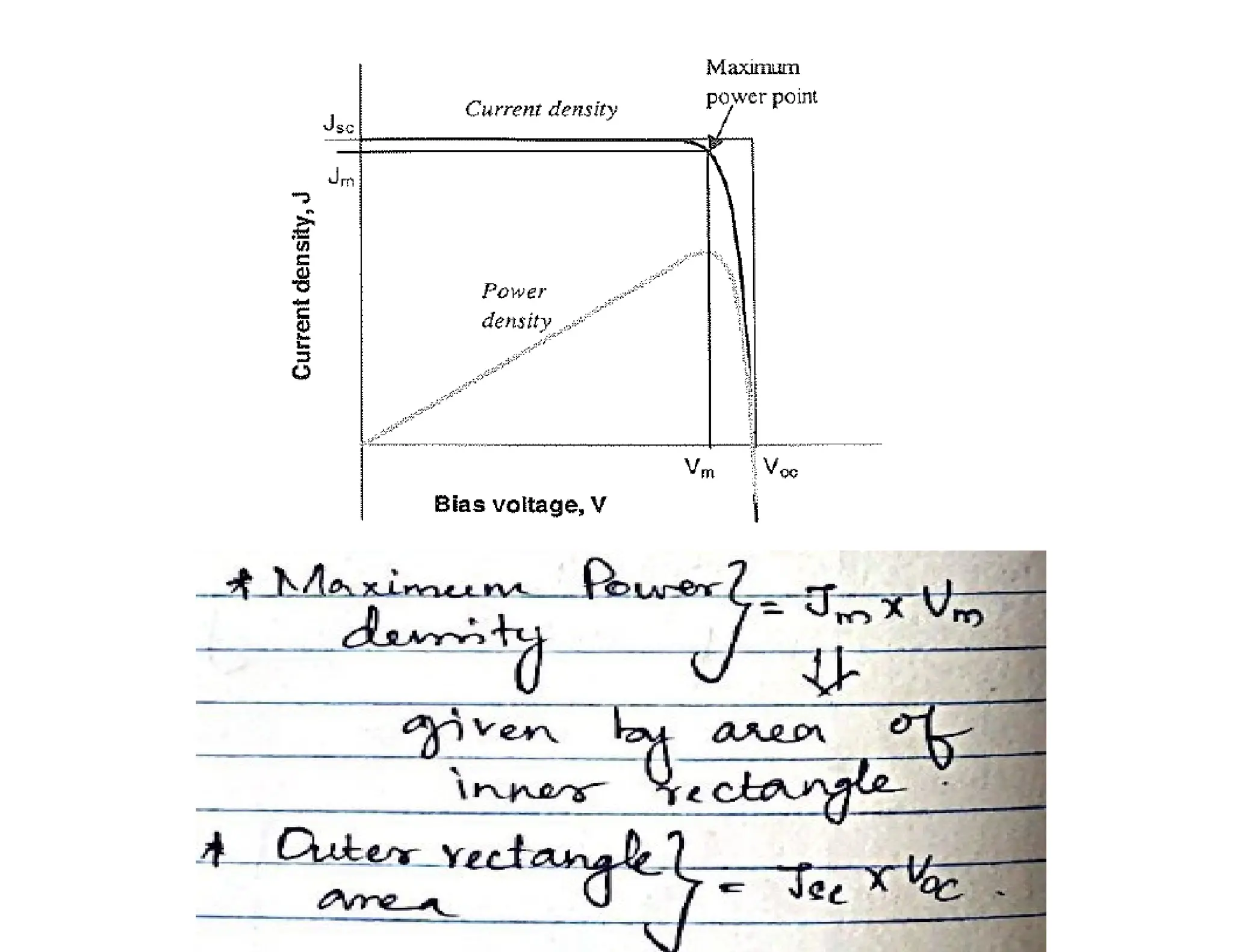
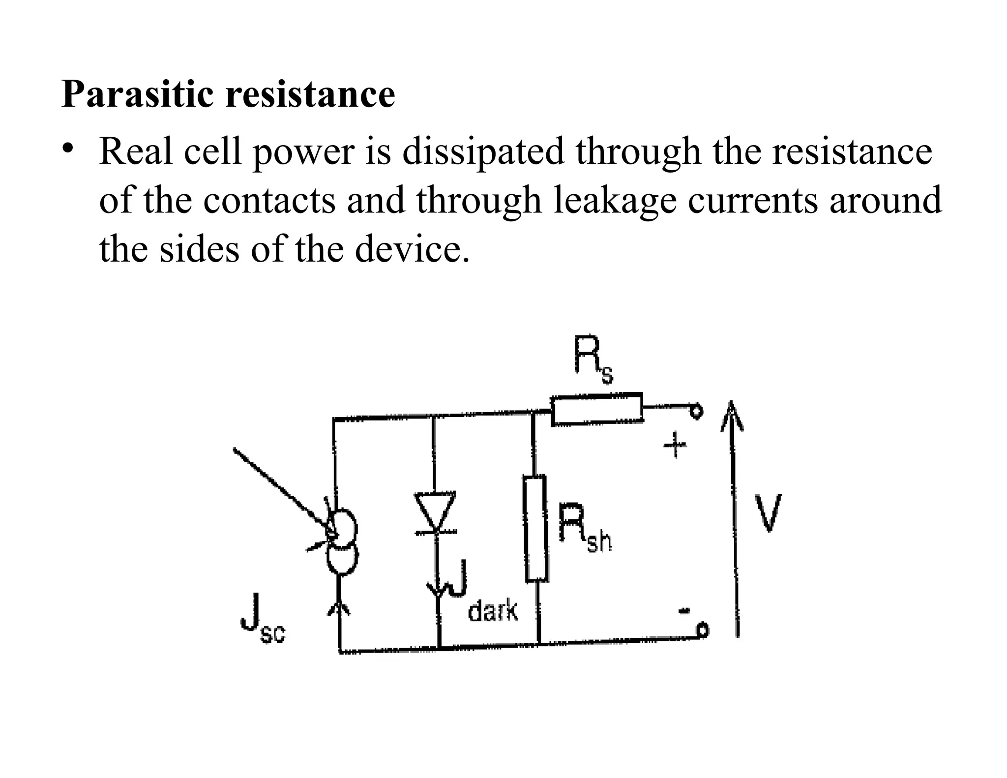
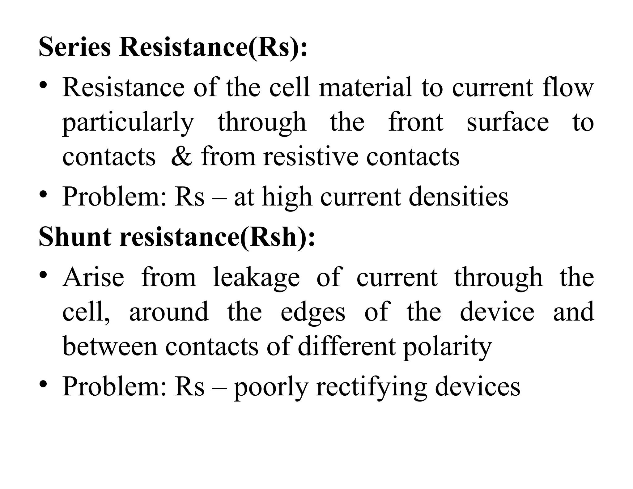
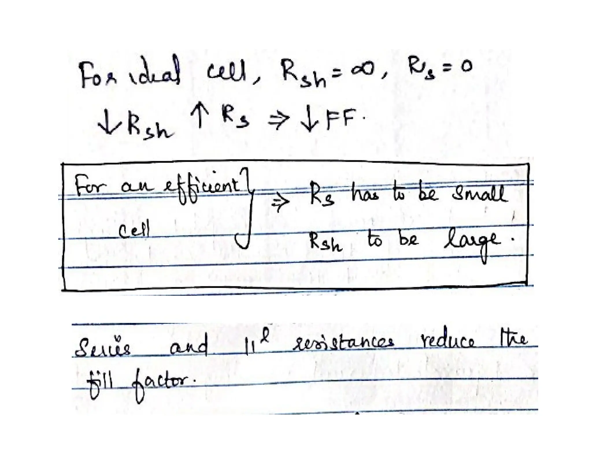
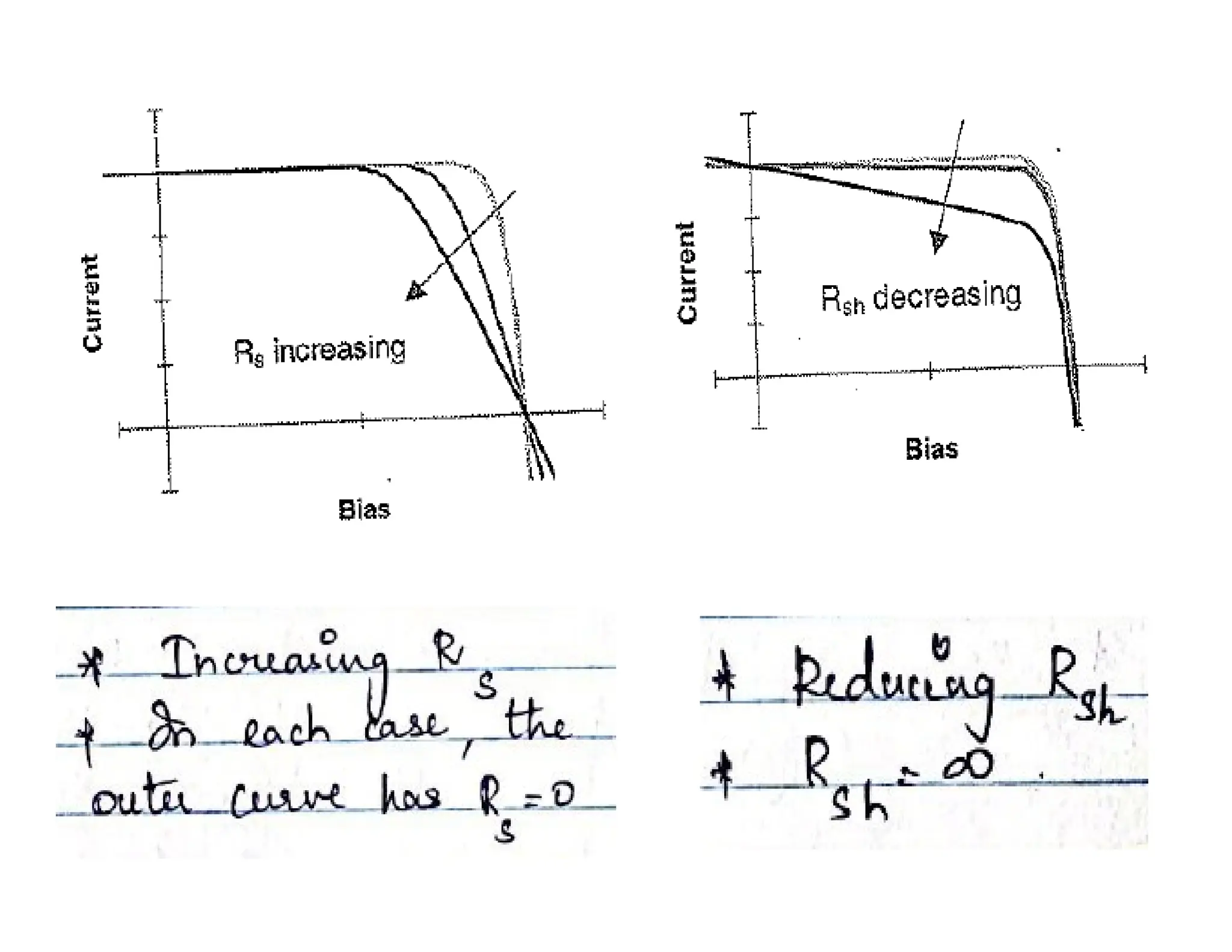
FUNDAMENTAL OF SOLAR CELLS
S.Gomathy
Assistant Professor(SrG)
Department of EEE
Average Solar Insolation
.... energizing Ohio for the 21st Century
Average Solar Radiation
Average daily solar radiation at a location in a given month: this data may be presented either as
measured on the horizontal or measured with the measuring surface perpendicular to the solar
radiation (corresponding to a PV system which tracks the sun). The angular dependence to account for
the tilt of the module must also be incorporated.
Peak Sun Hours
The average daily solar insolation in units of kWh/m2 per day is sometimes referred to as "peak sun
hours". The term "peak sun hours" refers to the solar insolation which a particular location would
receive if the sun were shining at its maximum value for a certain number of hours. Since the peak solar
radiation is 1 kW/m2, the number of peak sun hours is numerically identical to the average daily solar
insolation. For example, a location that receives 8 kWh/m2 per day can be said to have received 8 hours
of sun per day at 1 kW/m2. Being able to calculate the peak sun hours is useful because PV modules are
often rated at an input rating of 1kW/m2.
Simple solar cell structure
usable photo-
voltage (qV)
n-type
p-type
1 e--h+ pair/photon
hν
Conventional p-n junction
photovoltaic cell
Hot charge carriers
e-
electron loses
energy to
phonons
e-
hole loses
h+ energy to
phonons
Photovoltaic effect
The photovoltaic effect is the creation of a voltage (or a corresponding
electric current) in a material upon exposure to light.
Electric current flow
Conventional Electric Current
Although it is electrons which are the mobile charge carriers which are
responsible for electric current in conductors such as wires, it has long
been the convention to take the direction of electric current as if it
were the positive charges which are moving.
-
-
-
-
-
-
-
-
I
Insulators, semiconductors, and
conductors
The Fermi level is the energy, also called the chemical
potential (μ) that appears in the electrons' Fermi-Dirac
distribution function. A state at the Fermi level has a 50%
chance of being occupied by an electron.
The Diode Equation
Ideal Diodes
The diode equation gives an expression for the current through a diode as a function of
voltage. The
Ideal Diode Law:
where:
I = the net current flowing through the diode;
I0 = "dark saturation current", the diode leakage current density in the absence of
light;
V = applied voltage across the terminals of the diode;
q = absolute value of electron charge;
k = Boltzmann's constant; and
T = absolute temperature (K).
The "dark saturation current" (I0) is an extremely important parameter which
differentiates one diode from another. I0 is a measure of the recombination in a
device. A diode with a larger recombination will have a larger I0.
Note that:
I0 increases as T increases; and
I0 decreases as material quality increases.
At 300K, kT/q = 25.85 mV, the "thermal voltage".
Short circuit photocurrent
The short-circuit current (ISC) is the current through the solar cell when
the voltage across the solar cell is zero (i.e., when the solar cell is short
circuited). Usually written as ISC, the short-circuit current is shown on
the IV curve below.
ISC is due to the generation and collection of light-generated carriers. For an
ideal PV cell with moderate resistive loss, ISC and the light-generated
current are identical (ISC is the largest current which may be drawn from
the solar cell).
Open circuit photovoltage (VOC)
The open-circuit voltage, Voc, is the maximum voltage available
from a solar cell, and this occurs at zero current. The open-
circuit voltage corresponds to the amount of forward bias on
the solar cell due to the bias of the solar cell junction with the
light- generated current. The open-circuit voltage is shown on
the IV curve below.
Solar cell fill factor (FF)
Graph of cell output current (red line) and power (blue line) as function of voltage. Also
shown are the cell short-circuit current (Isc) and open-circuit voltage (Voc) points, as well as
the maximum power point (Vmp, Imp). Click on the graph to see how the curve changes for a
cell with low FF.
At both of the operating points corresponding to ISC and VOC, the power from the solar cell is
zero. The "fill factor“ (FF) is the parameter which, in conjunction with Voc and Isc, determines the
maximum power from a solar cell. The FF is defined as the ratio of the maximum power from
the solar cell to the product of Voc and Isc. Graphically, the FF is a measure of the "squareness" of
the solar cell and is also the area of the largest rectangle which will fit in the IV curve. The FF is
illustrated below:
Battery
• Emf-due to permanent
electrochemical potential
difference between 2 phase
in cell
• Power-constant
• Reaches the end of its life
• Voltage generator
Solar cell
• Emf-temporary charge in
electrochemical potential
caused by light
• Power-depends on light
intensity
• Never exhausted
• Current generator
Relationship between QE and Jsc
JSC  q bs E QEE dE
where bs(E) is the incident spectral photon flux density, i.e. the
number of photons in the energy range E to E + dE which are
incident on unit area in unit time, and q is the electronic charge.
QE depends upon the absorption coefficient of the solar cell
materials, the efficiency of charge separation, and the efficiency of
charge collection in the device; but it does not depend on the
incident spectrum.
Energy of a photon:
Bypass diodes & blocking diodes-To avoid losses
Bypass diodes - A diode, called bypass diode, is connected in
parallel with solar cells with opposite polarity to that of a solar cell.
• Blocking diodes are added in PV system to
avoid reverse flow of current into the PV
modules
Dark current
• When load is present, a potential difference develops
between the terminals of the cell.
• This potential difference generates a current which acts in
the opposite direction to the photocurrent
• This reverse current is called dark current
• I dark-flows across the device under an applied dark
voltage
• Solar cells behave like a diode in the dark(larger current
under forward bias v>0 than reverse bias v<0)
• For ideal diode, the dark current density Jdark
varies like
• Overall current voltage response of the cell=Short
circuit photocurrent+ Dark current
• This is known as “Superposition approximation”
• The net current density in the cell is
• Voltage between 0 & Voc – Cell generates
power
• V<0 – Photodetector – consuming power – to
generate a photocurrent – light dependent but
bias independent
• At V>Voc – Consumes power
Equivalent circuit of ideal solar cell
•When illuminated , the ideal cell produces a photocurrent
proportional to the light intensity
•Photocurrent divided between – Variable resistance of diode;
load
•For higher resistance- more photocurrent flows through the
diode – resulting in higher potential difference between the
cell terminals – smaller current through load
• Diode provides photovoltage
• Without diode, nothing to drive the photocurrent
through the load
Efficiency:
• Operating area of solar cell – from 0 to Voc, in
which the cell delivers power
• Cell power density P=JV
Fill Factor:
• The efficiency of the cell is the power density
delivered at operating point as fraction of the
incident light power density Ps
• These are the key performance characteristics
of a solar cell
• Standard Test Condition (STC):
– Air mass:1.5 spectrum
– Incident power density = 1000w/m2
– Temperature – 25degreeC
Parasitic resistance
• Real cell power is dissipated through the resistance
of the contacts and through leakage currents around
the sides of the device.
Series Resistance(Rs):
• Resistance of the cell material to current flow
particularly through the front surface to
contacts & from resistive contacts
• Problem: Rs – at high current densities
Shunt resistance(Rsh):
• Arise from leakage of current through the
cell, around the edges of the device and
between contacts of different polarity
• Problem: Rs – poorly rectifying devices
Non ideal diode behavior:
Non-ideal equation is given by
m=ideality factor
m – lies between 1 & 2

1.Introduction-Solar cell basics and working

  • 1.
    FUNDAMENTAL OF SOLARCELLS S.Gomathy Assistant Professor(SrG) Department of EEE
  • 2.
    Average Solar Insolation ....energizing Ohio for the 21st Century Average Solar Radiation Average daily solar radiation at a location in a given month: this data may be presented either as measured on the horizontal or measured with the measuring surface perpendicular to the solar radiation (corresponding to a PV system which tracks the sun). The angular dependence to account for the tilt of the module must also be incorporated. Peak Sun Hours The average daily solar insolation in units of kWh/m2 per day is sometimes referred to as "peak sun hours". The term "peak sun hours" refers to the solar insolation which a particular location would receive if the sun were shining at its maximum value for a certain number of hours. Since the peak solar radiation is 1 kW/m2, the number of peak sun hours is numerically identical to the average daily solar insolation. For example, a location that receives 8 kWh/m2 per day can be said to have received 8 hours of sun per day at 1 kW/m2. Being able to calculate the peak sun hours is useful because PV modules are often rated at an input rating of 1kW/m2.
  • 3.
  • 4.
    usable photo- voltage (qV) n-type p-type 1e--h+ pair/photon hν Conventional p-n junction photovoltaic cell Hot charge carriers e- electron loses energy to phonons e- hole loses h+ energy to phonons
  • 5.
    Photovoltaic effect The photovoltaiceffect is the creation of a voltage (or a corresponding electric current) in a material upon exposure to light.
  • 6.
    Electric current flow ConventionalElectric Current Although it is electrons which are the mobile charge carriers which are responsible for electric current in conductors such as wires, it has long been the convention to take the direction of electric current as if it were the positive charges which are moving. - - - - - - - - I
  • 7.
    Insulators, semiconductors, and conductors TheFermi level is the energy, also called the chemical potential (μ) that appears in the electrons' Fermi-Dirac distribution function. A state at the Fermi level has a 50% chance of being occupied by an electron.
  • 8.
    The Diode Equation IdealDiodes The diode equation gives an expression for the current through a diode as a function of voltage. The Ideal Diode Law: where: I = the net current flowing through the diode; I0 = "dark saturation current", the diode leakage current density in the absence of light; V = applied voltage across the terminals of the diode; q = absolute value of electron charge; k = Boltzmann's constant; and T = absolute temperature (K). The "dark saturation current" (I0) is an extremely important parameter which differentiates one diode from another. I0 is a measure of the recombination in a device. A diode with a larger recombination will have a larger I0. Note that: I0 increases as T increases; and I0 decreases as material quality increases. At 300K, kT/q = 25.85 mV, the "thermal voltage".
  • 9.
    Short circuit photocurrent Theshort-circuit current (ISC) is the current through the solar cell when the voltage across the solar cell is zero (i.e., when the solar cell is short circuited). Usually written as ISC, the short-circuit current is shown on the IV curve below. ISC is due to the generation and collection of light-generated carriers. For an ideal PV cell with moderate resistive loss, ISC and the light-generated current are identical (ISC is the largest current which may be drawn from the solar cell).
  • 10.
    Open circuit photovoltage(VOC) The open-circuit voltage, Voc, is the maximum voltage available from a solar cell, and this occurs at zero current. The open- circuit voltage corresponds to the amount of forward bias on the solar cell due to the bias of the solar cell junction with the light- generated current. The open-circuit voltage is shown on the IV curve below.
  • 11.
    Solar cell fillfactor (FF) Graph of cell output current (red line) and power (blue line) as function of voltage. Also shown are the cell short-circuit current (Isc) and open-circuit voltage (Voc) points, as well as the maximum power point (Vmp, Imp). Click on the graph to see how the curve changes for a cell with low FF. At both of the operating points corresponding to ISC and VOC, the power from the solar cell is zero. The "fill factor“ (FF) is the parameter which, in conjunction with Voc and Isc, determines the maximum power from a solar cell. The FF is defined as the ratio of the maximum power from the solar cell to the product of Voc and Isc. Graphically, the FF is a measure of the "squareness" of the solar cell and is also the area of the largest rectangle which will fit in the IV curve. The FF is illustrated below:
  • 12.
    Battery • Emf-due topermanent electrochemical potential difference between 2 phase in cell • Power-constant • Reaches the end of its life • Voltage generator Solar cell • Emf-temporary charge in electrochemical potential caused by light • Power-depends on light intensity • Never exhausted • Current generator
  • 13.
    Relationship between QEand Jsc JSC  q bs E QEE dE where bs(E) is the incident spectral photon flux density, i.e. the number of photons in the energy range E to E + dE which are incident on unit area in unit time, and q is the electronic charge. QE depends upon the absorption coefficient of the solar cell materials, the efficiency of charge separation, and the efficiency of charge collection in the device; but it does not depend on the incident spectrum. Energy of a photon:
  • 14.
    Bypass diodes &blocking diodes-To avoid losses Bypass diodes - A diode, called bypass diode, is connected in parallel with solar cells with opposite polarity to that of a solar cell.
  • 15.
    • Blocking diodesare added in PV system to avoid reverse flow of current into the PV modules
  • 16.
    Dark current • Whenload is present, a potential difference develops between the terminals of the cell. • This potential difference generates a current which acts in the opposite direction to the photocurrent • This reverse current is called dark current • I dark-flows across the device under an applied dark voltage • Solar cells behave like a diode in the dark(larger current under forward bias v>0 than reverse bias v<0)
  • 17.
    • For idealdiode, the dark current density Jdark varies like • Overall current voltage response of the cell=Short circuit photocurrent+ Dark current • This is known as “Superposition approximation”
  • 18.
    • The netcurrent density in the cell is
  • 19.
    • Voltage between0 & Voc – Cell generates power • V<0 – Photodetector – consuming power – to generate a photocurrent – light dependent but bias independent • At V>Voc – Consumes power
  • 20.
    Equivalent circuit ofideal solar cell •When illuminated , the ideal cell produces a photocurrent proportional to the light intensity •Photocurrent divided between – Variable resistance of diode; load •For higher resistance- more photocurrent flows through the diode – resulting in higher potential difference between the cell terminals – smaller current through load
  • 21.
    • Diode providesphotovoltage • Without diode, nothing to drive the photocurrent through the load Efficiency: • Operating area of solar cell – from 0 to Voc, in which the cell delivers power • Cell power density P=JV Fill Factor:
  • 22.
    • The efficiencyof the cell is the power density delivered at operating point as fraction of the incident light power density Ps • These are the key performance characteristics of a solar cell
  • 23.
    • Standard TestCondition (STC): – Air mass:1.5 spectrum – Incident power density = 1000w/m2 – Temperature – 25degreeC
  • 25.
    Parasitic resistance • Realcell power is dissipated through the resistance of the contacts and through leakage currents around the sides of the device.
  • 26.
    Series Resistance(Rs): • Resistanceof the cell material to current flow particularly through the front surface to contacts & from resistive contacts • Problem: Rs – at high current densities Shunt resistance(Rsh): • Arise from leakage of current through the cell, around the edges of the device and between contacts of different polarity • Problem: Rs – poorly rectifying devices
  • 30.
    Non ideal diodebehavior: Non-ideal equation is given by m=ideality factor m – lies between 1 & 2