Download as PPSX, PPTX

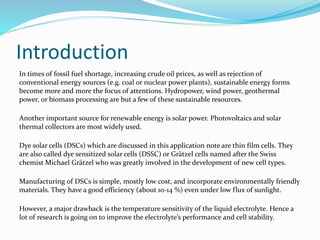

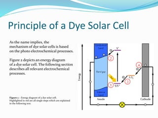


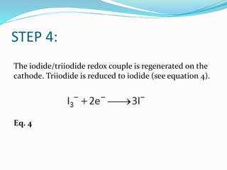


This document discusses the basic principles and measurements of dye solar cells. It begins by introducing dye solar cells and their advantages over other solar cell technologies. It then provides a simplified diagram of a dye solar cell's setup and components. The remainder of the document thoroughly explains the electrochemical processes and energy transfers that occur in a dye solar cell when exposed to light, including excitation of dye molecules, electron injection and transport, redox reactions, and regeneration of the electrolyte. It also defines and discusses important parameters that can be measured from dye solar cell I-V curves, such as short circuit current, open circuit potential, fill factor, series and shunt resistances, maximum power, and efficiency.


![Solar_Cells_and_the_Photovoltaic_Effect[1].pdf](https://cdn.slidesharecdn.com/ss_thumbnails/solarcellsandthephotovoltaiceffect1-250426224359-81b30574-thumbnail.jpg?width=640&height=640&fit=bounds)


![Human Reproduction [ Reproductive System ] Notes @irfanullah_mehar Irfanullah...](https://cdn.slidesharecdn.com/ss_thumbnails/humanreproductionreproductivesystemnotesirfanullahmeharirfanullahmeharjanantantra-260111172350-56e85778-thumbnail.jpg?width=640&height=640&fit=bounds)


