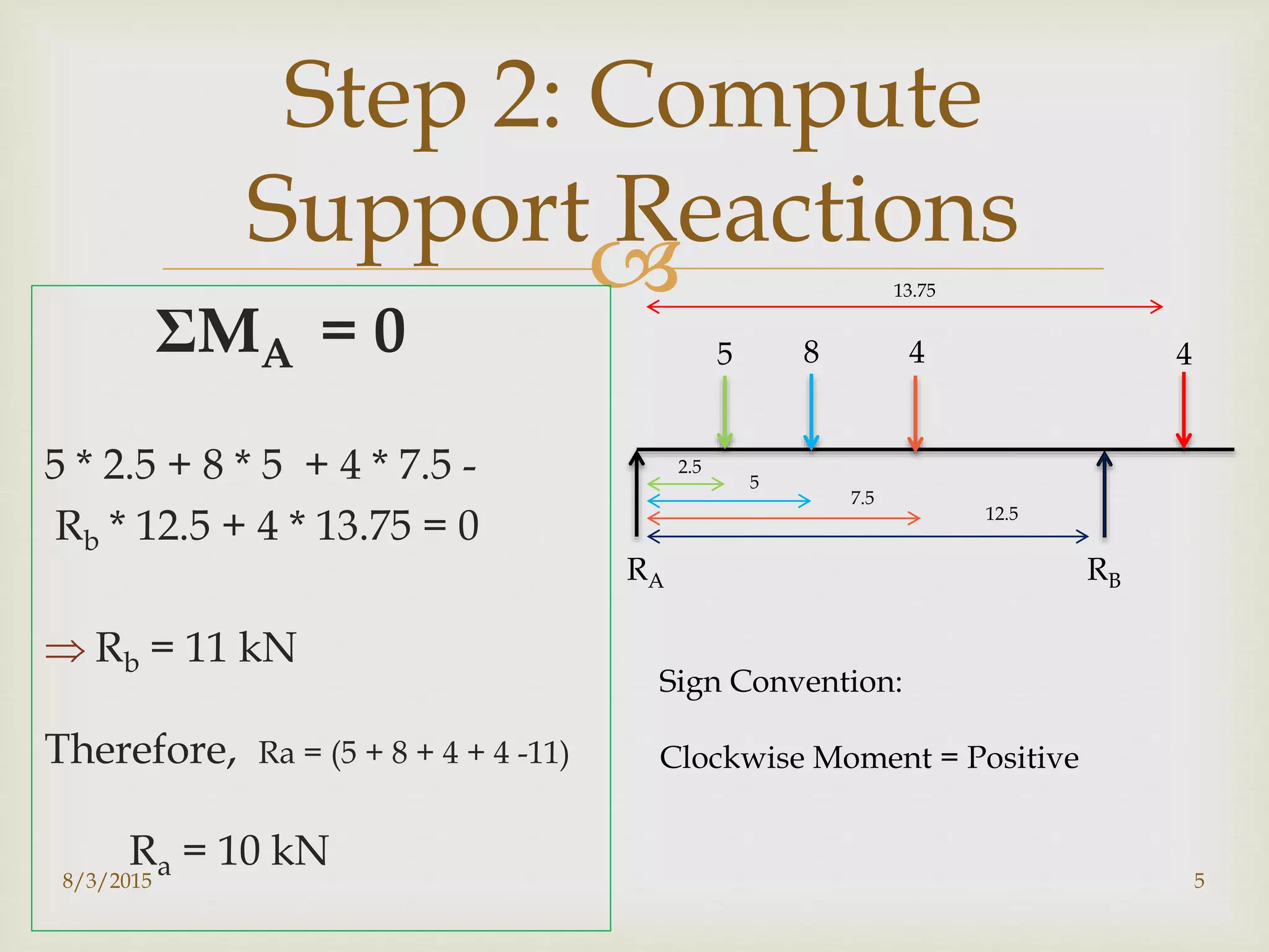
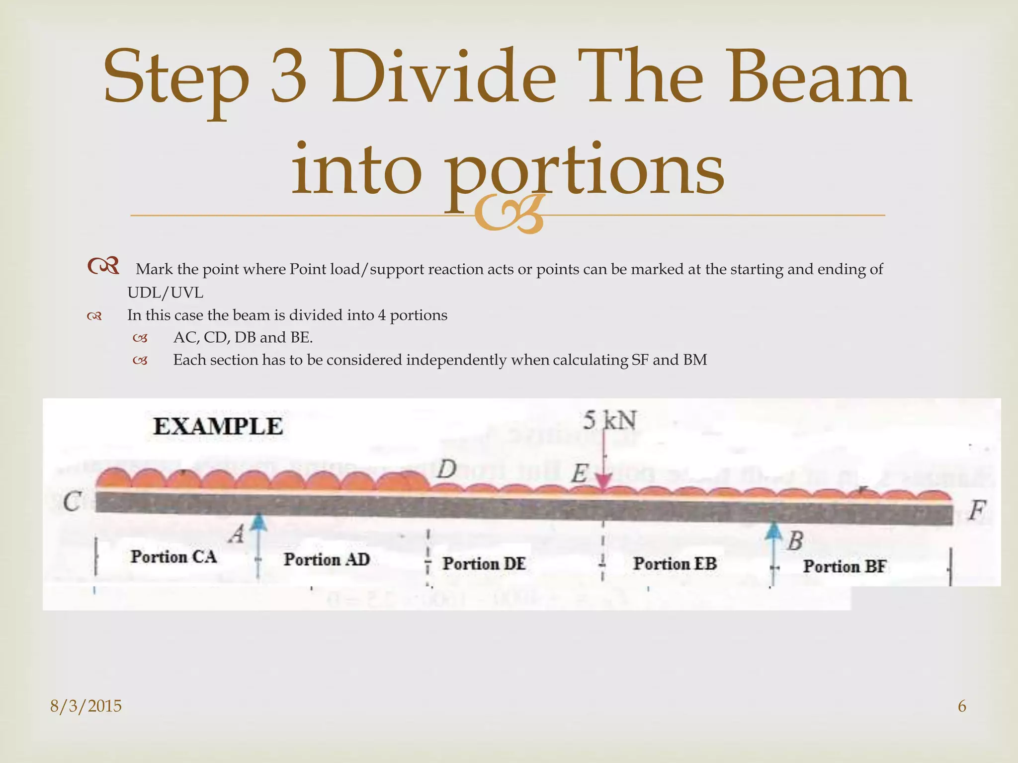
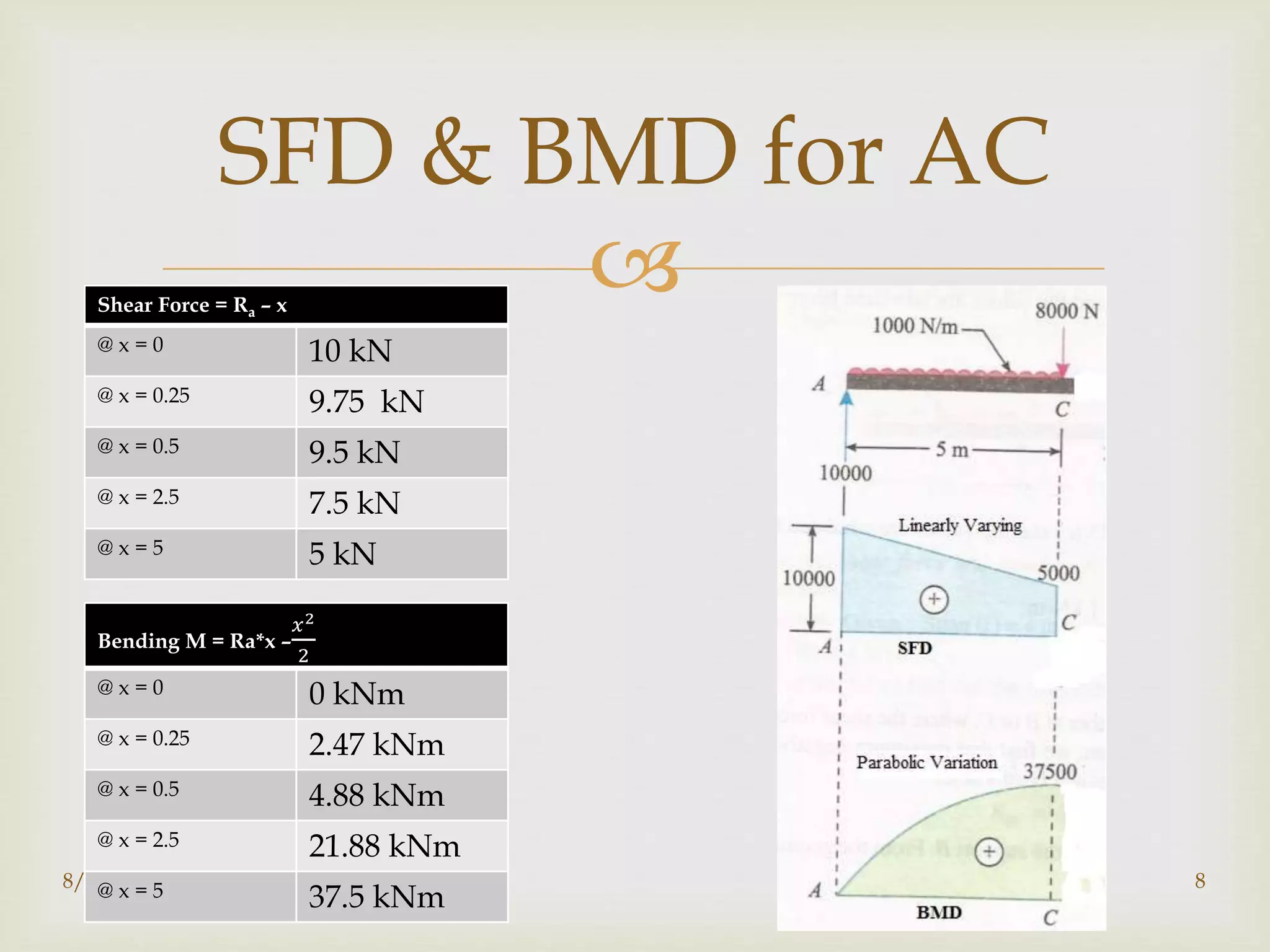
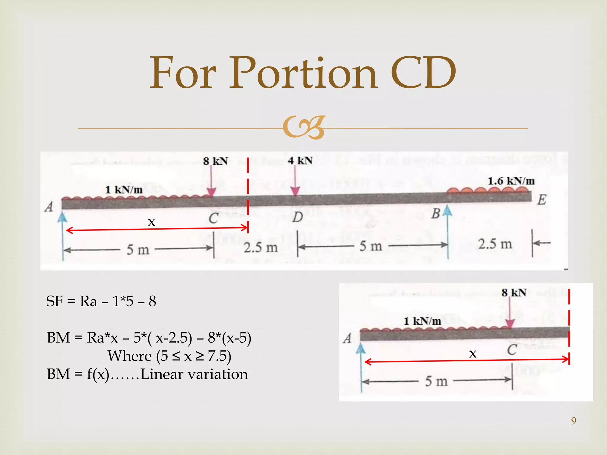
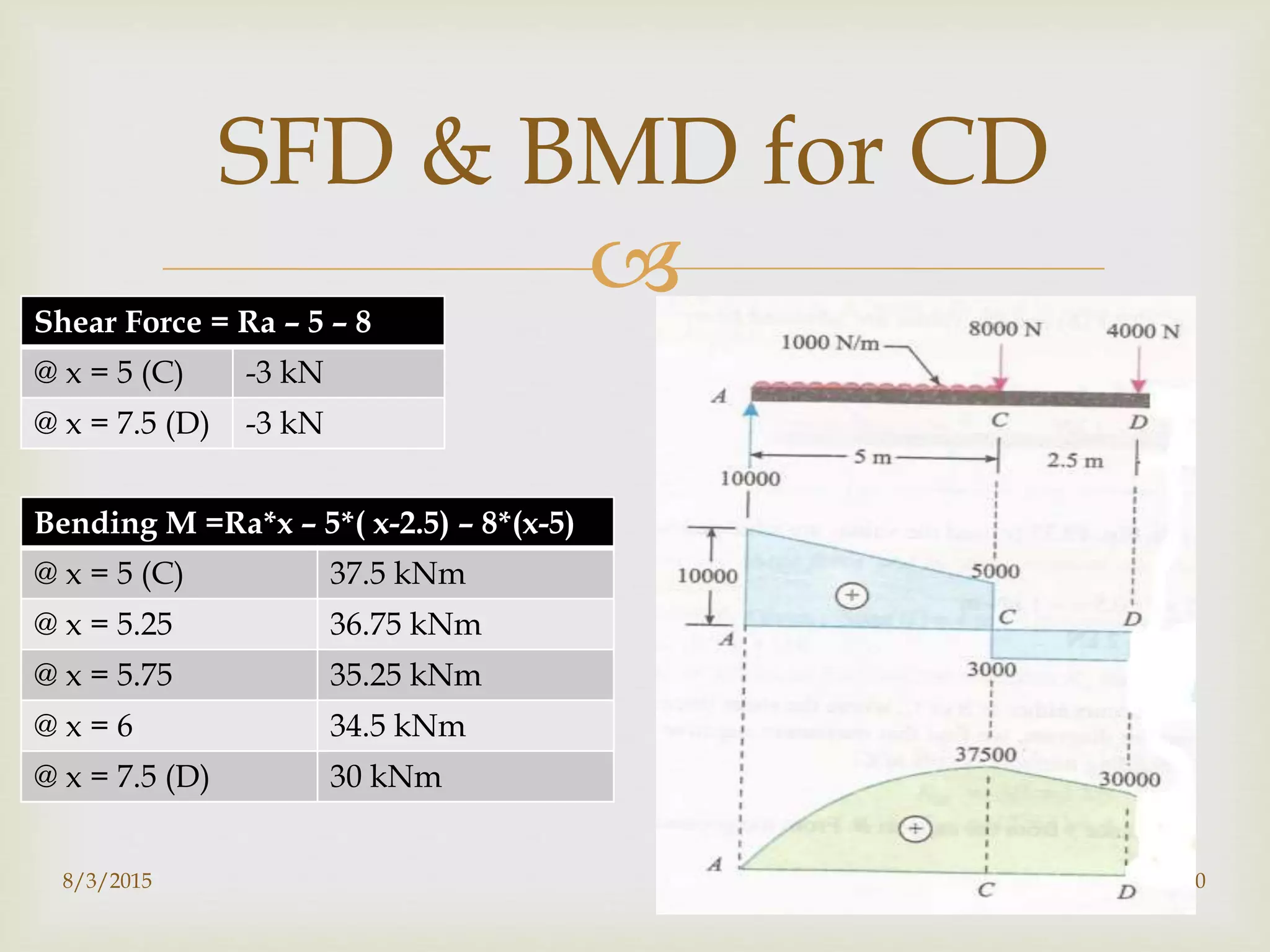
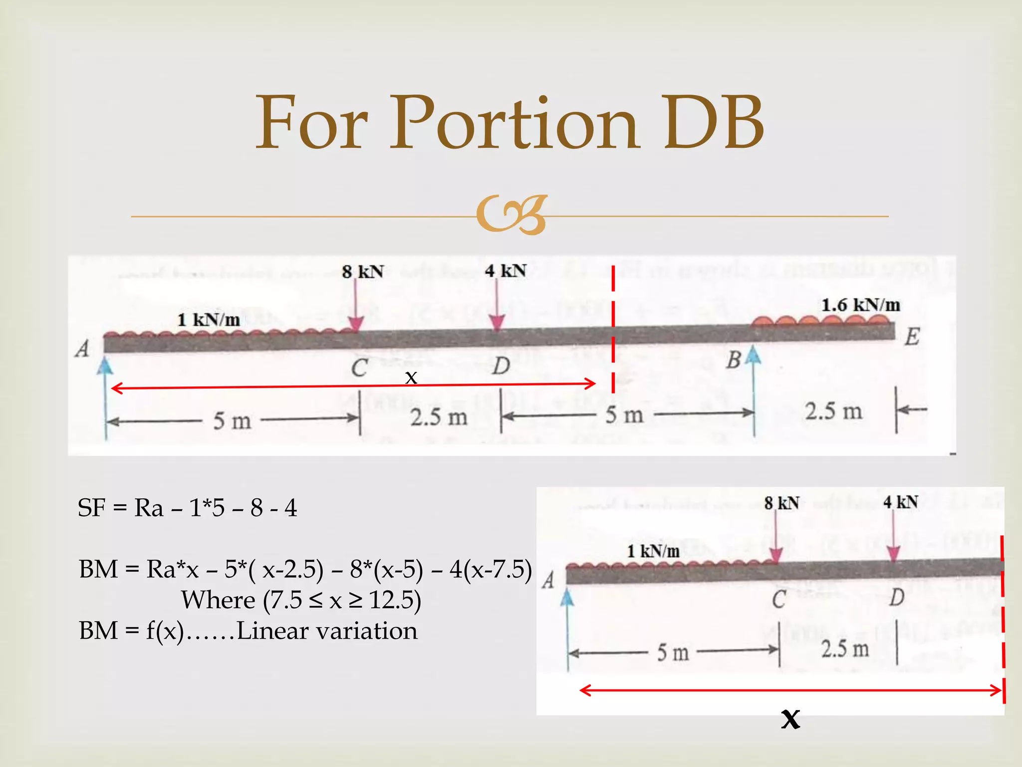
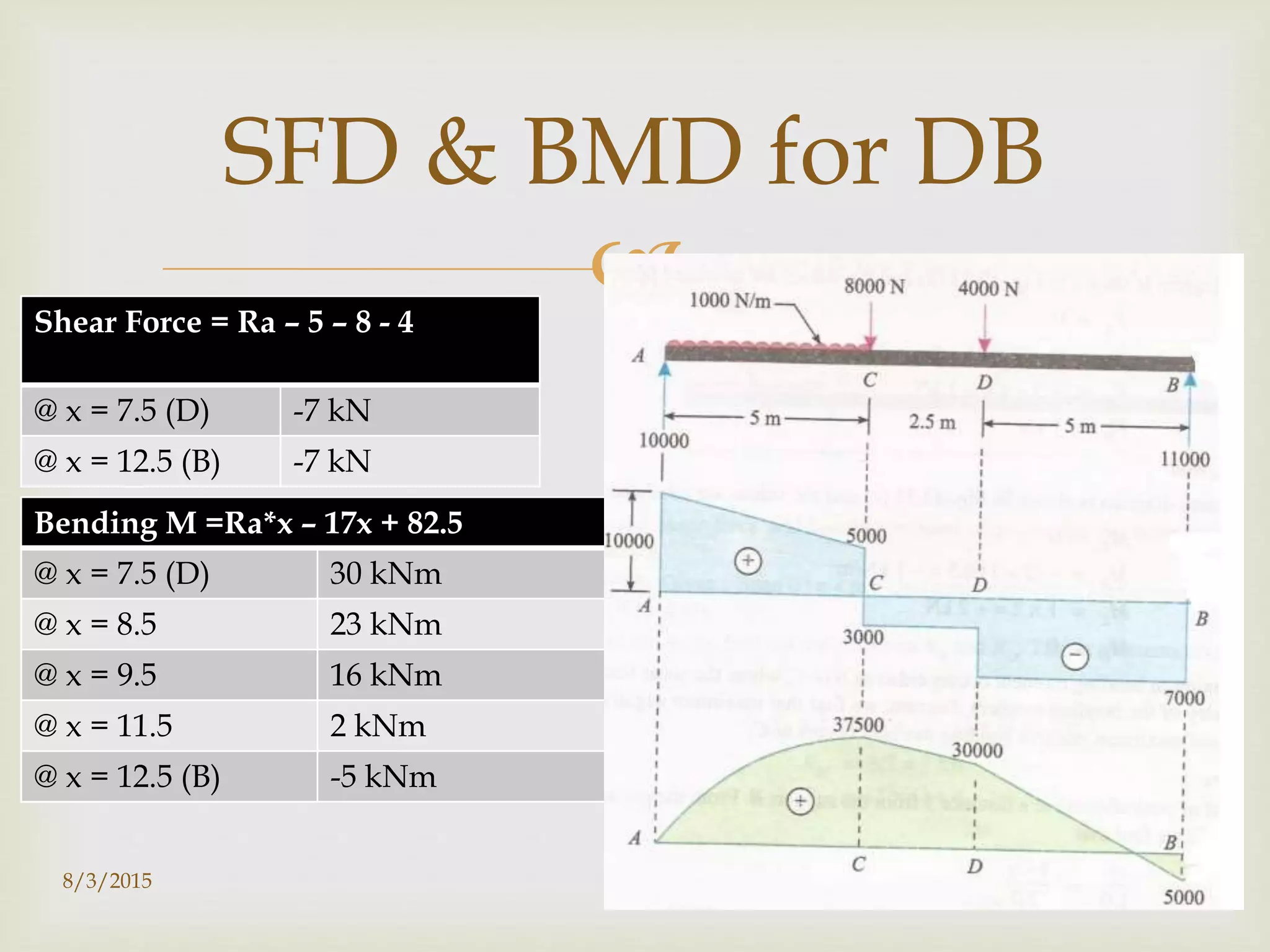
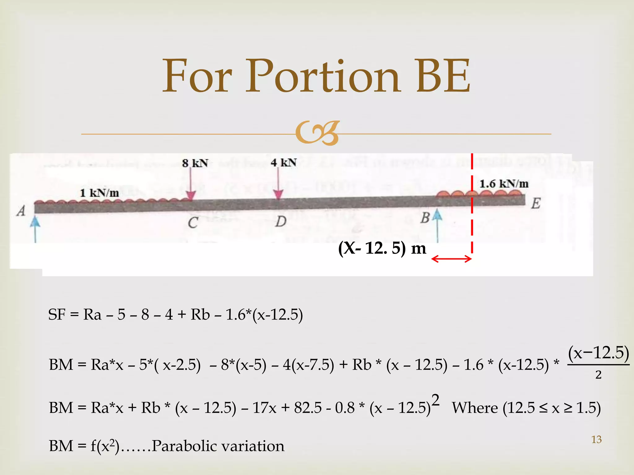
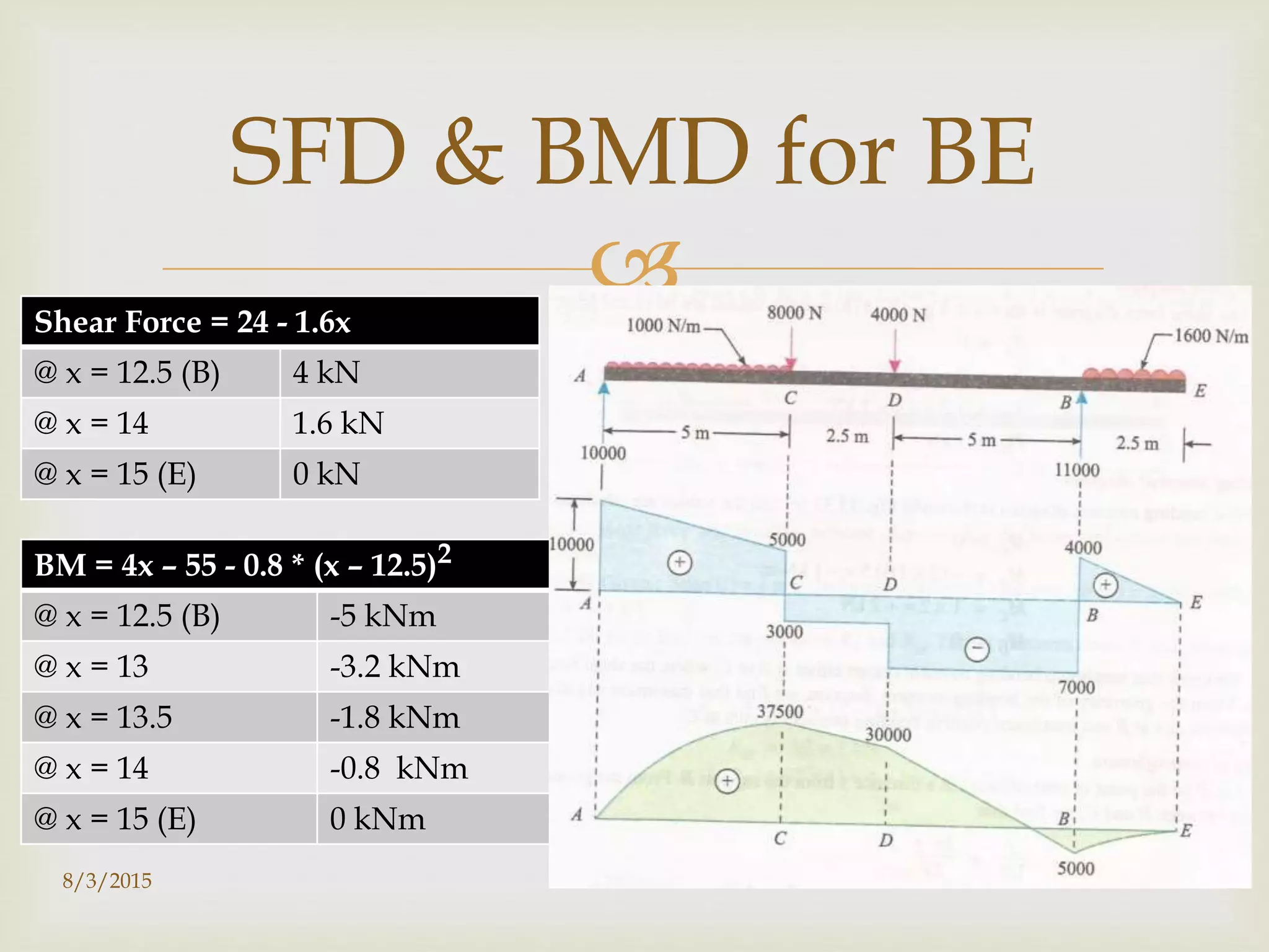
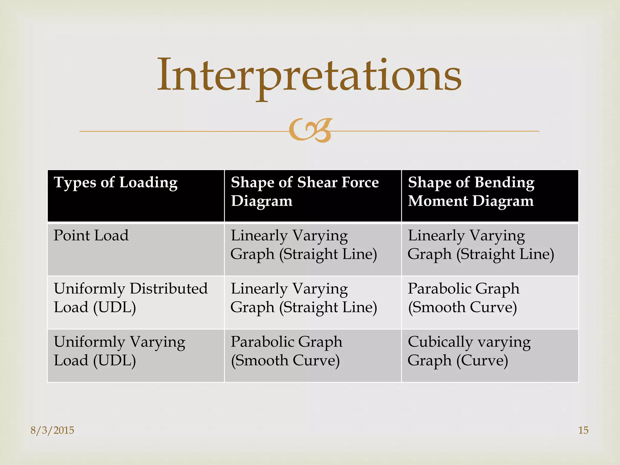

Shear Force and Bending Moment
(Solved Numerical)
Kirtan Adhikari
Assistant Lecturer
College of Science and Technology
Royal University of Bhutan
adhikari.cst@rub.edu.bt
COLLEGE OF SCIENCE AND TECHNOLOGY
ROYAL UNIVERSITY OF BHUTAN
RINCHENDING
BHUTAN
18/3/2015

 To understand the fundamental concept on Bending
Moment and Shear Force please read through text
books (References).
 This ppt contains step wise procedure to draw SFD
and BMD
8/3/2015 2
Important Note

Draw SFD and BMD of the beam shown below. Indicate the
numerical values at all important point
8/3/2015 3
Question 1

a) For any type of questions start by computing support reactions.
b) Draw Free Body Diagram of the beam
c) Convert UDL, UVL to point load to compute support reaction. (only to compute
support reaction)
8/3/2015 4
Step 1
RA RB
8 4
2.5 2.52.5 1.25 1.255
5 4

8/3/2015 5
Step 2: Compute
Support Reactions
ΣMA = 0
5 * 2.5 + 8 * 5 + 4 * 7.5 -
Rb * 12.5 + 4 * 13.75 = 0
 Rb = 11 kN
Therefore, Ra = (5 + 8 + 4 + 4 -11)
Ra = 10 kN
RA RB
8 45 4
Sign Convention:
Clockwise Moment = Positive
2.5
5
7.5
12.5
13.75

 Mark the point where Point load/support reaction acts or points can be marked at the starting and ending of
UDL/UVL
 In this case the beam is divided into 4 portions
 AC, CD, DB and BE.
 Each section has to be considered independently when calculating SF and BM
8/3/2015 6
Step 3 Divide The Beam
into portions

7
Step 5 Draw a sectional line anywhere in
portion AC
x
Shear force at a sectional point (at a distance x from A)
F = Ra – 1*x Where (0 ≤ x ≥ 5)
F = f(x)……….. This function produces straight line graph (Linear Variation)
Bending Moment at a sectional point (at a distance x from A)
BM = Ra*x – 1*x *
𝑥
2
Where (0 ≤ x ≥ 5)
BM = f(x2)…………….This function Produces a Parabolic curve
x

8/3/2015 8
SFD & BMD for AC
Shear Force = Ra – x
@ x = 0 10 kN
@ x = 0.25 9.75 kN
@ x = 0.5 9.5 kN
@ x = 2.5 7.5 kN
@ x = 5 5 kN
Bending M = Ra*x –
𝑥2
2
@ x = 0 0 kNm
@ x = 0.25 2.47 kNm
@ x = 0.5 4.88 kNm
@ x = 2.5 21.88 kNm
@ x = 5 37.5 kNm

9
For Portion CD
x
x
SF = Ra – 1*5 – 8
BM = Ra*x – 5*( x-2.5) – 8*(x-5)
Where (5 ≤ x ≥ 7.5)
BM = f(x)……Linear variation

8/3/2015 10
SFD & BMD for CD
Shear Force = Ra – 5 – 8
@ x = 5 (C) -3 kN
@ x = 7.5 (D) -3 kN
Bending M =Ra*x – 5*( x-2.5) – 8*(x-5)
@ x = 5 (C) 37.5 kNm
@ x = 5.25 36.75 kNm
@ x = 5.75 35.25 kNm
@ x = 6 34.5 kNm
@ x = 7.5 (D) 30 kNm

11
For Portion DB
x
SF = Ra – 1*5 – 8 - 4
BM = Ra*x – 5*( x-2.5) – 8*(x-5) – 4(x-7.5)
Where (7.5 ≤ x ≥ 12.5)
BM = f(x)……Linear variation
x

8/3/2015 12
SFD & BMD for DB
Shear Force = Ra – 5 – 8 - 4
@ x = 7.5 (D) -7 kN
@ x = 12.5 (B) -7 kN
Bending M =Ra*x – 17x + 82.5
@ x = 7.5 (D) 30 kNm
@ x = 8.5 23 kNm
@ x = 9.5 16 kNm
@ x = 11.5 2 kNm
@ x = 12.5 (B) -5 kNm

13
For Portion BE
SF = Ra – 5 – 8 – 4 + Rb – 1.6*(x-12.5)
BM = Ra*x – 5*( x-2.5) – 8*(x-5) – 4(x-7.5) + Rb * (x – 12.5) – 1.6 * (x-12.5) *
(x−12.5)
2
BM = Ra*x + Rb * (x – 12.5) – 17x + 82.5 - 0.8 * (x – 12.5)2 Where (12.5 ≤ x ≥ 1.5)
BM = f(x2)……Parabolic variation
x(X- 5) m(X- 7. 5) m(X- 12. 5) m

8/3/2015 14
SFD & BMD for BE
Shear Force = 24 - 1.6x
@ x = 12.5 (B) 4 kN
@ x = 14 1.6 kN
@ x = 15 (E) 0 kN
BM = 4x – 55 - 0.8 * (x – 12.5)2
@ x = 12.5 (B) -5 kNm
@ x = 13 -3.2 kNm
@ x = 13.5 -1.8 kNm
@ x = 14 -0.8 kNm
@ x = 15 (E) 0 kNm

Types of Loading Shape of Shear Force
Diagram
Shape of Bending
Moment Diagram
Point Load Linearly Varying
Graph (Straight Line)
Linearly Varying
Graph (Straight Line)
Uniformly Distributed
Load (UDL)
Linearly Varying
Graph (Straight Line)
Parabolic Graph
(Smooth Curve)
Uniformly Varying
Load (UDL)
Parabolic Graph
(Smooth Curve)
Cubically varying
Graph (Curve)
8/3/2015 15
Interpretations
1. R.S.Khurmi. Strength of Materials. New Delhi: S.Chand & Company Ltd.
2. Timoshenko, S.P., and D.H. Young (1993). Elements of Strength of Materials.(5th
Ed.).East West Press.
3. Bhavikari, S. S., 2008. Strength of Materials. 3rd ed. Delhi: Vikas Publishing House
Pvt Ltd.
4. Ramamrutham, S. & Narayan, R., 2009. Setrength of Materials. Noida: Dhanpat Rai
Publishing Company (P) Ltd
5. A.R.Jain and B.K.Jain (1987). Theory and Analysis of Structures, Vol. Roorkee:
Nemchand and Bros.
6. B.C.Punmia (1994). Strength of Materials and Theory of Structures, Vol. 1. New Delhi:
Laxmi publications.
7. M. M. Ratwani & V.N.Vazirani (2008). Analysis of Structure, Vol.1. New Delhi:
Khanna Publishers.
8. R.K. Bansal (1994). A Text Book on Strength of Materials. New Delhi: Laxmi
Publications.
9. R.K. Rajput.(2007). Strength of Materials. New Delhi: S.Chand & Company Ltd
8/3/2015 16
References
17
Thank You
8/3/2015

Shear force and bending moment Solved Numerical

  • 1.
     Shear Force andBending Moment (Solved Numerical) Kirtan Adhikari Assistant Lecturer College of Science and Technology Royal University of Bhutan adhikari.cst@rub.edu.bt COLLEGE OF SCIENCE AND TECHNOLOGY ROYAL UNIVERSITY OF BHUTAN RINCHENDING BHUTAN 18/3/2015
  • 2.
      To understandthe fundamental concept on Bending Moment and Shear Force please read through text books (References).  This ppt contains step wise procedure to draw SFD and BMD 8/3/2015 2 Important Note
  • 3.
     Draw SFD andBMD of the beam shown below. Indicate the numerical values at all important point 8/3/2015 3 Question 1
  • 4.
     a) For anytype of questions start by computing support reactions. b) Draw Free Body Diagram of the beam c) Convert UDL, UVL to point load to compute support reaction. (only to compute support reaction) 8/3/2015 4 Step 1 RA RB 8 4 2.5 2.52.5 1.25 1.255 5 4
  • 5.
     8/3/2015 5 Step 2:Compute Support Reactions ΣMA = 0 5 * 2.5 + 8 * 5 + 4 * 7.5 - Rb * 12.5 + 4 * 13.75 = 0  Rb = 11 kN Therefore, Ra = (5 + 8 + 4 + 4 -11) Ra = 10 kN RA RB 8 45 4 Sign Convention: Clockwise Moment = Positive 2.5 5 7.5 12.5 13.75
  • 6.
      Mark thepoint where Point load/support reaction acts or points can be marked at the starting and ending of UDL/UVL  In this case the beam is divided into 4 portions  AC, CD, DB and BE.  Each section has to be considered independently when calculating SF and BM 8/3/2015 6 Step 3 Divide The Beam into portions
  • 7.
     7 Step 5 Drawa sectional line anywhere in portion AC x Shear force at a sectional point (at a distance x from A) F = Ra – 1*x Where (0 ≤ x ≥ 5) F = f(x)……….. This function produces straight line graph (Linear Variation) Bending Moment at a sectional point (at a distance x from A) BM = Ra*x – 1*x * 𝑥 2 Where (0 ≤ x ≥ 5) BM = f(x2)…………….This function Produces a Parabolic curve x
  • 8.
     8/3/2015 8 SFD &BMD for AC Shear Force = Ra – x @ x = 0 10 kN @ x = 0.25 9.75 kN @ x = 0.5 9.5 kN @ x = 2.5 7.5 kN @ x = 5 5 kN Bending M = Ra*x – 𝑥2 2 @ x = 0 0 kNm @ x = 0.25 2.47 kNm @ x = 0.5 4.88 kNm @ x = 2.5 21.88 kNm @ x = 5 37.5 kNm
  • 9.
     9 For Portion CD x x SF= Ra – 1*5 – 8 BM = Ra*x – 5*( x-2.5) – 8*(x-5) Where (5 ≤ x ≥ 7.5) BM = f(x)……Linear variation
  • 10.
     8/3/2015 10 SFD &BMD for CD Shear Force = Ra – 5 – 8 @ x = 5 (C) -3 kN @ x = 7.5 (D) -3 kN Bending M =Ra*x – 5*( x-2.5) – 8*(x-5) @ x = 5 (C) 37.5 kNm @ x = 5.25 36.75 kNm @ x = 5.75 35.25 kNm @ x = 6 34.5 kNm @ x = 7.5 (D) 30 kNm
  • 11.
     11 For Portion DB x SF= Ra – 1*5 – 8 - 4 BM = Ra*x – 5*( x-2.5) – 8*(x-5) – 4(x-7.5) Where (7.5 ≤ x ≥ 12.5) BM = f(x)……Linear variation x
  • 12.
     8/3/2015 12 SFD &BMD for DB Shear Force = Ra – 5 – 8 - 4 @ x = 7.5 (D) -7 kN @ x = 12.5 (B) -7 kN Bending M =Ra*x – 17x + 82.5 @ x = 7.5 (D) 30 kNm @ x = 8.5 23 kNm @ x = 9.5 16 kNm @ x = 11.5 2 kNm @ x = 12.5 (B) -5 kNm
  • 13.
     13 For Portion BE SF= Ra – 5 – 8 – 4 + Rb – 1.6*(x-12.5) BM = Ra*x – 5*( x-2.5) – 8*(x-5) – 4(x-7.5) + Rb * (x – 12.5) – 1.6 * (x-12.5) * (x−12.5) 2 BM = Ra*x + Rb * (x – 12.5) – 17x + 82.5 - 0.8 * (x – 12.5)2 Where (12.5 ≤ x ≥ 1.5) BM = f(x2)……Parabolic variation x(X- 5) m(X- 7. 5) m(X- 12. 5) m
  • 14.
     8/3/2015 14 SFD &BMD for BE Shear Force = 24 - 1.6x @ x = 12.5 (B) 4 kN @ x = 14 1.6 kN @ x = 15 (E) 0 kN BM = 4x – 55 - 0.8 * (x – 12.5)2 @ x = 12.5 (B) -5 kNm @ x = 13 -3.2 kNm @ x = 13.5 -1.8 kNm @ x = 14 -0.8 kNm @ x = 15 (E) 0 kNm
  • 15.
     Types of LoadingShape of Shear Force Diagram Shape of Bending Moment Diagram Point Load Linearly Varying Graph (Straight Line) Linearly Varying Graph (Straight Line) Uniformly Distributed Load (UDL) Linearly Varying Graph (Straight Line) Parabolic Graph (Smooth Curve) Uniformly Varying Load (UDL) Parabolic Graph (Smooth Curve) Cubically varying Graph (Curve) 8/3/2015 15 Interpretations
  • 16.
    1. R.S.Khurmi. Strengthof Materials. New Delhi: S.Chand & Company Ltd. 2. Timoshenko, S.P., and D.H. Young (1993). Elements of Strength of Materials.(5th Ed.).East West Press. 3. Bhavikari, S. S., 2008. Strength of Materials. 3rd ed. Delhi: Vikas Publishing House Pvt Ltd. 4. Ramamrutham, S. & Narayan, R., 2009. Setrength of Materials. Noida: Dhanpat Rai Publishing Company (P) Ltd 5. A.R.Jain and B.K.Jain (1987). Theory and Analysis of Structures, Vol. Roorkee: Nemchand and Bros. 6. B.C.Punmia (1994). Strength of Materials and Theory of Structures, Vol. 1. New Delhi: Laxmi publications. 7. M. M. Ratwani & V.N.Vazirani (2008). Analysis of Structure, Vol.1. New Delhi: Khanna Publishers. 8. R.K. Bansal (1994). A Text Book on Strength of Materials. New Delhi: Laxmi Publications. 9. R.K. Rajput.(2007). Strength of Materials. New Delhi: S.Chand & Company Ltd 8/3/2015 16 References
  • 17.