
Downloaded 62 times
![International Journal of Technical Research and Applications e-ISSN: 2320-8163,
www.ijtra.com Volume 2, Issue 1 (Jan-Feb 2014), PP. 33-35
33 | P a g e
STUDY THE WORKING STRESS
METHOD AND LIMIT STATE METHOD
AND IN RCC CHIMNEY DESIGN
RajaVarma
Department Of Civil Engineering
Saroj Institute of Technology & Management
Abstract – Every industry focus to build and improve the
chimney to create the eco-friend organization as well as to
satisfy the strict environmental board.
IS: 4998 criteria for design of reinforced concrete chimneys
is using working stress method for chimney designing.
There are some limitations of working stress method. Also
the designing is difficult involving lengthy, cumbersome
and iterative computational effort.
So we should recognize this problem and we should use
some time saving techniques like interaction envelopes to
optimize the structural design.
Chimneys with various heights from 65m to 280m are
analyzed and designed by working stress method and limit
state method for collapse and comparison of results are
discussed in this paper. Generation of interaction curves for
hollow circular section is also discussed in this paper.
Key words: Reinforced Concrete Chimneys; Limit State
Method; Working Stress Method; Pu-Mu Interaction curves
I. INTRODUCTION
Chimneys, as we all know today, are hollow, tall and
slender vertical structures that carry smoke or steam
away from a fire or engine at a high enough elevation so
that after dilution due to atmospheric turbulence, their
concentration and that of their entrained solid
particulates is within acceptable limits on reaching the
ground.
IS: 4998 (Part I) CRITERIA FOR DESIGN OF
REINFORCED CONCRETE CHIMNEYS [1][2]
is using
working stress method for chimney designing.
The working stress method, though ensures satisfactory
performance at the working loads, is unrealistic and
irrational at ultimate load and it does not guarantee the
satisfactory performance of the structure at service loads.
The working stress method is logically not applicable to
concrete structures because this method assumes that the
materials of which the structure is made up, namely
concrete and steel, both obey Hook’s law. The
applicability of the Hook’s law is rather limited in
respect of concrete structures.
Among the advantages claimed for the limit state
approach are that the degree of safety of the various parts
of a structure is more uniform and also that a
probabilistic approach to safety is possible. To ensure
satisfactory performance of a structure serviceability
check like check for deflection and cracking is also
needed which are considered in limit state method.
II. ANALYSIS OF CHIMNEY
The chimney shall be divided in to ten or more sections
along its height and the load at any section shall be
calculated by suitable averaging the loads above it. The
moments are calculated from the sectional forces treating
the chimney as cantilever structure.
Analysis consist of calculation of factored dead load
(W) which includes Shell weight, Brick lining weight
and wind load according to IS: 4998 (Part I)[1] [2]
, then
factored moment (M) because of this wind load is
calculated at section.
III. DESIGNING
A. Working Stress Method
Chimney is designed according to IS: 4998 (Part I) [1] [2]
and following steps are followed:
1. Determine eccentricity (e) = M/W
2. Determine (eccentricity/radius) at section
3. Assume the p (percentage of steel at section) at
the section under consideration
4. Select the value of m (modular ratio)for concrete
grade to be used
5. Determine α (position of neutral axis)
6. Determine compressive stresses for different
values of α and β (β = constant depends on
openings in chimneys) in concrete and steel
7. Calculate temperature stresses in steel and
concrete
8. Calculate stresses in steel and concrete due to
wind induced moment. And check combined
stresses
B. Limit State Method for Collapse
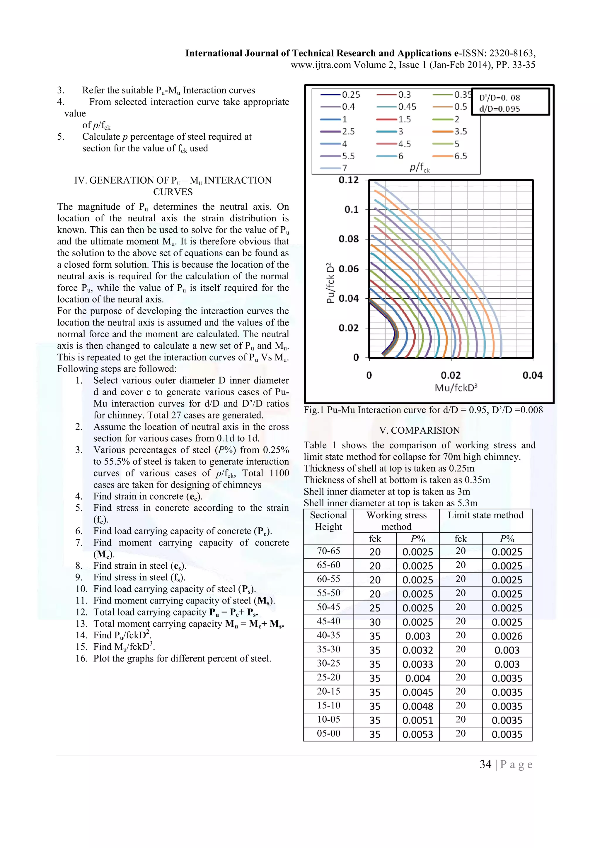
1. Calculate the W/fck D2
and M / fck D3
.
2. Calculate ratio d/D and D’/D
Where, d=inner diameter of concrete shell
D=outer diameter of concrete shell
D’=D - concrete cover](https://image.slidesharecdn.com/ijtra131204-151002141004-lva1-app6892/75/STUDY-THE-WORKING-STRESS-METHOD-AND-LIMIT-STATE-METHOD-AND-IN-RCC-CHIMNEY-DESIGN-1-2048.jpg)
![International Journal of Technical Research and Applications e-ISSN: 2320-8163,
www.ijtra.com Volume 2, Issue 1 (Jan-Feb 2014), PP. 33-35
35 | P a g e
Table 1 comparison of working stress method and limit
state method limit of collapse for chimney of height
70m.
Result shows that Limit State method is much more
economical than working stress method.
VI. FUTURE SCOPE
Earthquake forces consideration is beyond the scope,
also chimneys with openings and chimneys without
lining are beyond the scope.
Limit State of serviceability is beyond the scope.
REFERENCES
[1] IS: 4998 (Part I) – 1975
Criteria for design of reinforce concrete chimney.
[2] IS: 4998 (Part I) – 1992 (Revised edition)
Criteria for design of reinforced concrete
chimneys
[3] CICIND (Part A: The shell) – 2001 (Revised
edition)
Model code for concrete chimneys
[4] IS: 875 (Part 3: wind loads) – 1987
Code of practice for design loads (other than
earthquake) for buildings and structure
[5] IS: 456 - 2000
Plain and reinforced concrete code of practice
[6] SP: 16
Design aids for reinforced concrete to is: 456 –
1978
[7] Limit State Theory and Design of Reinforced
Concrete
By Dr. V. L. Shah and Late Dr. S. R. Karve
[8] Design of Tall Chimneys
By Mr. S. N. Manohar
[9] Load –moment interaction envelopes for design of
tall stacks –
A limit state approach by K. S. Babu Narayan and
Subhash C. Yaragal](https://image.slidesharecdn.com/ijtra131204-151002141004-lva1-app6892/75/STUDY-THE-WORKING-STRESS-METHOD-AND-LIMIT-STATE-METHOD-AND-IN-RCC-CHIMNEY-DESIGN-3-2048.jpg)
The document discusses the design methodologies for reinforced concrete chimneys, specifically comparing the Working Stress Method and Limit State Method. It highlights the limitations of the Working Stress Method and advocates for the more efficient Limit State Method, which provides uniform safety and includes serviceability checks. The paper analyzes chimneys of various heights and presents interaction curves for structural optimization, concluding that the Limit State Method is more economical.


