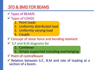
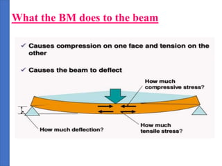
STRENGTH OF MATERIALS
SFD AND BMD
key points
SFD & BMD FOR BEAMS
 Types of BEAMS
 Types of LOADS
1. Point loads
2. Uniformly distributed load
3. Uniformly varying load
4. Couple
 Concept of shear force and bending moment
 S.F and B.M diagrams for
1. Cantilever
2. Simply supported including overhanging
 Point of contraflexure
 Relation between S.F., B.M and rate of loading at a
section of a beam.
Beam - Definition
Beam
 is the horizontal member of a structure
 carrying transverse loads
 transfer all the loads including its self-weight to the
columns or walls.
Transverse Load
 perpendicular to longitudinal axis of beam
https://www.youtube.com/watch?v=5K27dJqGpf8
Moment and Bending moment
Moment:
 It is the product of force and perpendicular
distance between line of action of the force and
the point about which moment is required to be
calculated.
Bending Moment (BM):
 The moment which causes the bending effect
on the beam is called Bending Moment. It is
generally denoted by ‘M’ or ‘BM’.
Shear Force and Bending Moment
Shear force at a section:
 The algebraic sum of the vertical forces acting
on the beam either to the left or right of the
section.
Bending moment (BM) at section:
 The algebraic sum of the moments of all
forces acting on the beam either to the left or
right of the section
What the BM does to the beam
Shear Force and Bending Moment Diagrams
SFD:
The diagram which shows the variation of shear
force along the length of the beam is called Shear
Force Diagram (SFD).
BMD:
The diagram which along the length shows the
variation of bending moment of the beam is called
Bending Moment Diagram (BMD).
Sign Conversion for S.F
F
F
F
F
+ ve shear
force
- ve shear force
Sign Convension for B.M
Sagging B.M
 The bending moment that tends to bend the beam to
a curvature having convexity at the bottom
 Sagging Bending Moment is considered as positive
bending moment.
Convexity
Sign Conversion for B.M Cont…
Hogging B.M
 Bending moment that tends to bend the beam to a
curvature having convexity at the top.
 Hogging Bending Moment is considered as Negative
Bending Moment
Convexity
Application of SFD & BMD
 To know the exact placement of
reinforcement in the structure to counteracts
the force and moment.
 for shear - stirrups are used in lateral direction
 For bending - bars are used in longitudinal
direction
Point of Contra flexure :
 It is the point on the bending moment
diagram where B.M changes the sign from
+ve to –ve or vice versa.
Important points for drawing SFD and BMD
1. Length of S.F.D and B.M.D must be equal to the
span of the beam.
2. S.F.D is drawn below the loaded beam and B.M.D
is drawn below S.F.D
3. For Simply supported beam B.M is zero at the
supports.
4. For cantilever beam B.M will be zero at free end.
5. Calculate S.F and B.M at all critical points
6. If no load is present between two points, then S.F
will be constant.
7. Consider the left or right side portion of the section
Important points for drawing SFD and BMD
Cont…
8. Add the forces (including reaction) normal to the
beam on one of the portion. (By considering sign
conversion)
9. The positive values of S.F and B.M are plotted
above the base line and Negative values below the
base line
10. The S.F.D will increase or degrease suddenly i.e.
by a vertical straight line at a section where there is
a vertical point load.
11. The S.F between any two vertical loads will be
constant and hence the S.F.D between two vertical
loads will be horizontal.
Relationship Between w, F, and M
 Rate of change of shear force is equal to rate of
loading
dF/dx = w
 Rate of change of bending moment is equal to
shear force
dM/dx = F

SFD BMD

  • 1.
    STRENGTH OF MATERIALS SFDAND BMD key points
  • 2.
    SFD & BMDFOR BEAMS  Types of BEAMS  Types of LOADS 1. Point loads 2. Uniformly distributed load 3. Uniformly varying load 4. Couple  Concept of shear force and bending moment  S.F and B.M diagrams for 1. Cantilever 2. Simply supported including overhanging  Point of contraflexure  Relation between S.F., B.M and rate of loading at a section of a beam.
  • 3.
    Beam - Definition Beam is the horizontal member of a structure  carrying transverse loads  transfer all the loads including its self-weight to the columns or walls. Transverse Load  perpendicular to longitudinal axis of beam
  • 4.
  • 5.
    Moment and Bendingmoment Moment:  It is the product of force and perpendicular distance between line of action of the force and the point about which moment is required to be calculated. Bending Moment (BM):  The moment which causes the bending effect on the beam is called Bending Moment. It is generally denoted by ‘M’ or ‘BM’.
  • 6.
    Shear Force andBending Moment Shear force at a section:  The algebraic sum of the vertical forces acting on the beam either to the left or right of the section. Bending moment (BM) at section:  The algebraic sum of the moments of all forces acting on the beam either to the left or right of the section
  • 7.
    What the BMdoes to the beam
  • 8.
    Shear Force andBending Moment Diagrams SFD: The diagram which shows the variation of shear force along the length of the beam is called Shear Force Diagram (SFD). BMD: The diagram which along the length shows the variation of bending moment of the beam is called Bending Moment Diagram (BMD).
  • 9.
    Sign Conversion forS.F F F F F + ve shear force - ve shear force
  • 10.
    Sign Convension forB.M Sagging B.M  The bending moment that tends to bend the beam to a curvature having convexity at the bottom  Sagging Bending Moment is considered as positive bending moment. Convexity
  • 11.
    Sign Conversion forB.M Cont… Hogging B.M  Bending moment that tends to bend the beam to a curvature having convexity at the top.  Hogging Bending Moment is considered as Negative Bending Moment Convexity
  • 12.
    Application of SFD& BMD  To know the exact placement of reinforcement in the structure to counteracts the force and moment.  for shear - stirrups are used in lateral direction  For bending - bars are used in longitudinal direction
  • 13.
    Point of Contraflexure :  It is the point on the bending moment diagram where B.M changes the sign from +ve to –ve or vice versa.
  • 14.
    Important points fordrawing SFD and BMD 1. Length of S.F.D and B.M.D must be equal to the span of the beam. 2. S.F.D is drawn below the loaded beam and B.M.D is drawn below S.F.D 3. For Simply supported beam B.M is zero at the supports. 4. For cantilever beam B.M will be zero at free end. 5. Calculate S.F and B.M at all critical points 6. If no load is present between two points, then S.F will be constant. 7. Consider the left or right side portion of the section
  • 15.
    Important points fordrawing SFD and BMD Cont… 8. Add the forces (including reaction) normal to the beam on one of the portion. (By considering sign conversion) 9. The positive values of S.F and B.M are plotted above the base line and Negative values below the base line 10. The S.F.D will increase or degrease suddenly i.e. by a vertical straight line at a section where there is a vertical point load. 11. The S.F between any two vertical loads will be constant and hence the S.F.D between two vertical loads will be horizontal.
  • 16.
    Relationship Between w,F, and M  Rate of change of shear force is equal to rate of loading dF/dx = w  Rate of change of bending moment is equal to shear force dM/dx = F