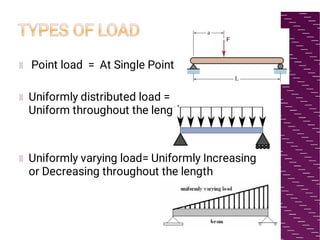
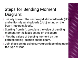
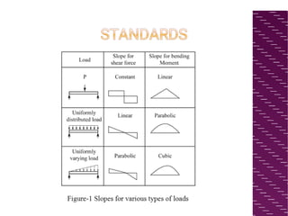
SFD & BMD
PART- I
By- Deepshikha Jain
STRENGTH OF
MATERIALS
WHAT IS SHEAR FORCE
AND BENDING MOMENT?
Shear Force-
It is defined as the algebraically of all forces at
either left side or right side of the beam.
Bending Moment-
It is defined as the algebraically sum of all
moments at either left side or right side of the
beam.
TYPES OF LOAD
 Point load  = At Single Point
Uniformly distributed load =
Uniform throughout the length
Uniformly varying load= Uniformly Increasing
or Decreasing throughout the length
SIGNIFICANCE
Shear force diagram and bending moment
diagrams are illustrations to describe the
alterations in shear force and bending
moments over the length of the beam.
These diagrams can be utilized to analyze the
failure of the structure with the given inputs
like loads, structure material, and shape.
Hence, SFD and BMD reduce the probability
of the structure's failure..
Steps for Shear Force Diagram:
Determine the internal forces (reactions) at the
supports and use sign conventions. Take the
upward force as positive and downward force as
negative.
Starting from left, plot the shear force values with
respect to the point of action on the beam.
The curvature for joining these points depends
upon the type of load.
The Shear Force Diagram should start and end at
x-axis (SF equals to zero) at the ends. Maximum
bending moment exists at the location where the
SFD crosses the axis.
Steps for Bending Moment
Diagram:
Initially convert the uniformly distributed loads (UDL)
and uniformly varying loads (UVL) acting on the
beam into point loads.
Starting from left, calculate the value of bending
moment for the loads acting on the beam.
Plot the values of bending moment on the
corresponding location on the beam.
Join these points using curvatures depending upon
the type of load.
STANDARDS
THANK YOU

Introduction And Concepts: SFD & BMD

  • 1.
    SFD & BMD PART-I By- Deepshikha Jain STRENGTH OF MATERIALS
  • 2.
    WHAT IS SHEARFORCE AND BENDING MOMENT? Shear Force- It is defined as the algebraically of all forces at either left side or right side of the beam. Bending Moment- It is defined as the algebraically sum of all moments at either left side or right side of the beam.
  • 3.
    TYPES OF LOAD  Pointload  = At Single Point Uniformly distributed load = Uniform throughout the length Uniformly varying load= Uniformly Increasing or Decreasing throughout the length
  • 4.
    SIGNIFICANCE Shear force diagramand bending moment diagrams are illustrations to describe the alterations in shear force and bending moments over the length of the beam. These diagrams can be utilized to analyze the failure of the structure with the given inputs like loads, structure material, and shape. Hence, SFD and BMD reduce the probability of the structure's failure..
  • 5.
    Steps for ShearForce Diagram: Determine the internal forces (reactions) at the supports and use sign conventions. Take the upward force as positive and downward force as negative. Starting from left, plot the shear force values with respect to the point of action on the beam. The curvature for joining these points depends upon the type of load. The Shear Force Diagram should start and end at x-axis (SF equals to zero) at the ends. Maximum bending moment exists at the location where the SFD crosses the axis.
  • 6.
    Steps for BendingMoment Diagram: Initially convert the uniformly distributed loads (UDL) and uniformly varying loads (UVL) acting on the beam into point loads. Starting from left, calculate the value of bending moment for the loads acting on the beam. Plot the values of bending moment on the corresponding location on the beam. Join these points using curvatures depending upon the type of load.
  • 7.
  • 8.