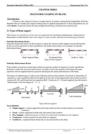
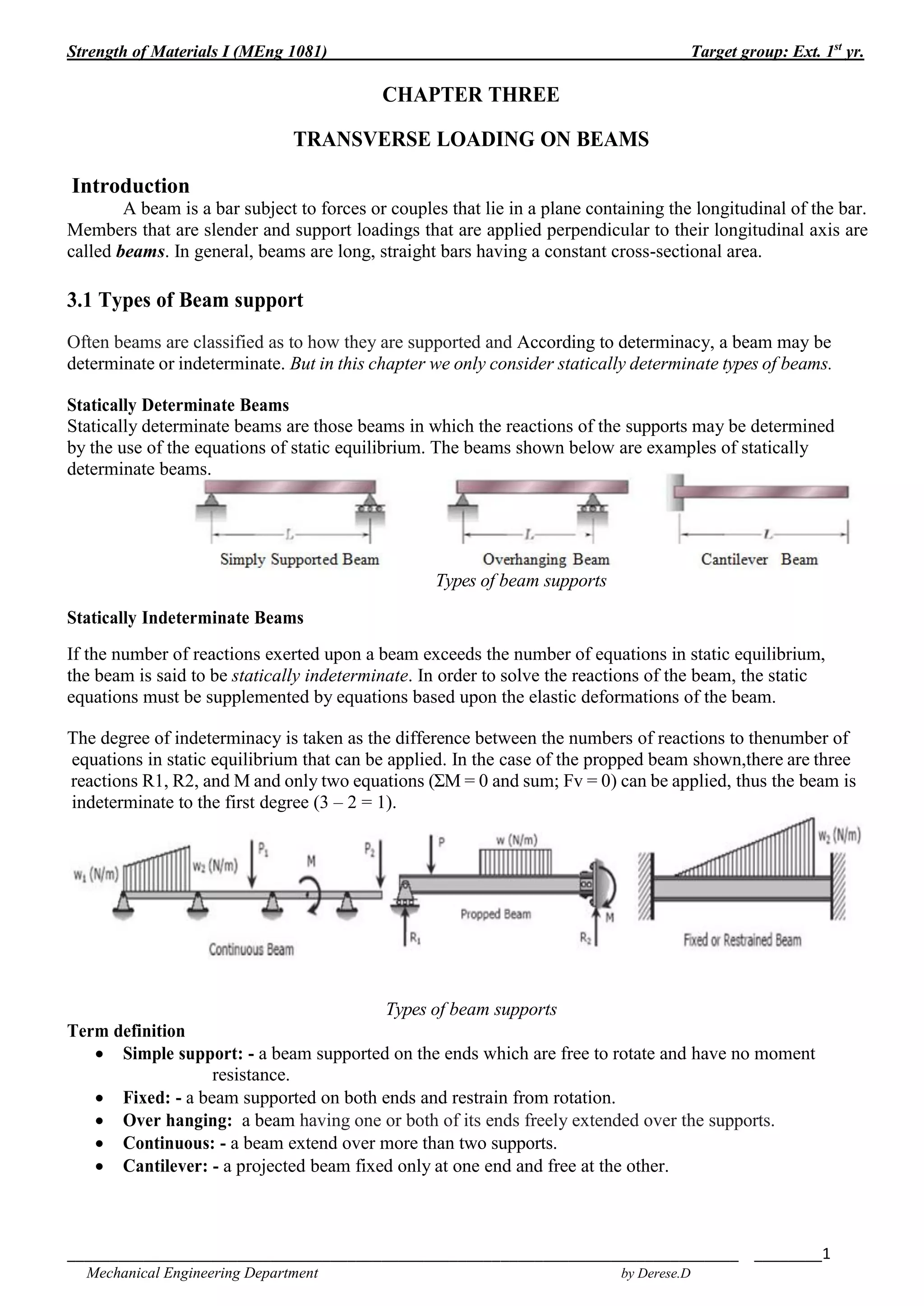
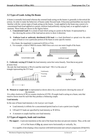
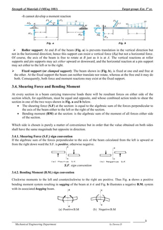
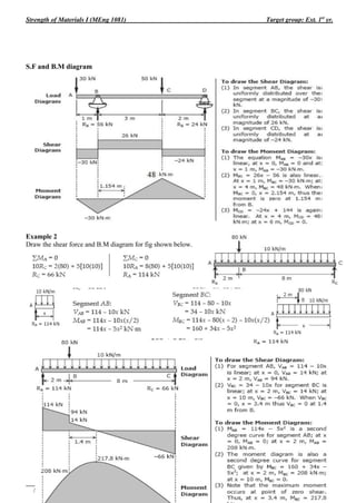
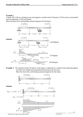
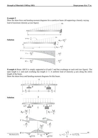
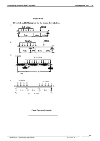
This document discusses transverse loading on beams. It defines different types of beam supports including simple, fixed, overhanging, continuous, and cantilever. It also describes different types of loads acting on beams such as concentrated, uniform, uniformly varying, and moment loads. It provides conventions for determining the sign of shear forces and bending moments on beams. Examples are given to demonstrate calculating shear forces and bending moments at different points on beams subjected to various load configurations.
This document discusses bending moments and shear forces in beams. It defines different types of beams such as simply supported beams, cantilever beams, and beams with overhangs. It also defines types of loads like concentrated loads, distributed loads, and couples. It explains how to calculate the shear force and bending moment at any cross-section of a beam and discusses relationships between loads, shear forces and bending moments. It provides examples of drawing shear force and bending moment diagrams. Finally, it discusses bending stresses in beams and bending of beams made of two materials.
B Ending Moments And Shearing Forces In Beams2Amr Hamed
This document discusses bending moments and shear forces in beams. It defines different types of beams such as simply supported beams, cantilever beams, and beams with overhangs. It also defines types of loads like concentrated loads, distributed loads, and couples. It explains how to calculate the shear force and bending moment at any cross-section of a beam and discusses relationships between loads, shear forces and bending moments. It provides examples of drawing shear force and bending moment diagrams. Finally, it discusses bending stresses in beams and bending of beams made of two materials.
The document provides information about mechanics of solids-I, including:
1) It describes different types of supports like simple supports, roller supports, pin-joint supports, and fixed supports. It also describes different types of loads like concentrated loads, uniformly distributed loads, and uniformly varying loads.
2) It discusses shear force as the unbalanced vertical force on one side of a beam section, and bending moment as the sum of moments about a section.
3) It explains the relationship between loading (w), shear force (F), and bending moment (M) for an element of a beam. The rate of change of shear force is equal to the loading intensity, and the rate of change of bending
This document provides information about bending moment in a presentation on pre-stress concrete design. It defines bending moment as a measure of bending forces acting on a beam, measured in terms of force and distance. Shear and moment diagrams can show the bending moment and shear force functions along a beam. Bending moment at a section is the sum of moments of all forces on one side and is represented in a bending moment diagram. Positive bending moment results in tension on the bottom fibers while negative bending moment results in compression. Bending moment units are Newton-meters or foot-pounds. Assumptions of simple bending theory and the differences between shear force and bending moment are also outlined.
This document provides information about bending moment in a presentation on pre-stress concrete design. It defines bending moment as a measure of bending forces acting on a beam, measured in terms of force and distance. Shear and moment diagrams can show the bending moment and shear force functions along a beam. Bending moment at a section is the sum of moments of all forces on one side and can be represented in a bending moment diagram. Positive bending moment results in tension on the bottom fibers while negative bending moment results in compression. Bending moment is measured in units of Newton-meters or foot-pounds. Simple bending theory makes assumptions about beam properties and behavior.
This document discusses shear force and bending moment in beams. It defines different types of beams, loads, and supports. Equations for calculating shear force and bending moment are presented for various beam configurations under different loading conditions, including cantilever beams with point loads and uniform loads, and simply supported beams with point and uniform loads. Diagrams illustrating the variation of shear force and bending moment along beams are shown as examples.
This document discusses bending moments and shear forces in beams. It defines different types of beams such as simply supported beams, cantilever beams, and beams with overhangs. It also defines types of loads like concentrated loads, distributed loads, and couples. It explains how to calculate the shear force and bending moment at any cross-section of a beam and discusses relationships between loads, shear forces and bending moments. It provides examples of drawing shear force and bending moment diagrams. Finally, it discusses bending stresses in beams and bending of beams made of two materials.
B Ending Moments And Shearing Forces In Beams2Amr Hamed
This document discusses bending moments and shear forces in beams. It defines different types of beams such as simply supported beams, cantilever beams, and beams with overhangs. It also defines types of loads like concentrated loads, distributed loads, and couples. It explains how to calculate the shear force and bending moment at any cross-section of a beam and discusses relationships between loads, shear forces and bending moments. It provides examples of drawing shear force and bending moment diagrams. Finally, it discusses bending stresses in beams and bending of beams made of two materials.
The document provides information about mechanics of solids-I, including:
1) It describes different types of supports like simple supports, roller supports, pin-joint supports, and fixed supports. It also describes different types of loads like concentrated loads, uniformly distributed loads, and uniformly varying loads.
2) It discusses shear force as the unbalanced vertical force on one side of a beam section, and bending moment as the sum of moments about a section.
3) It explains the relationship between loading (w), shear force (F), and bending moment (M) for an element of a beam. The rate of change of shear force is equal to the loading intensity, and the rate of change of bending
This document provides information about bending moment in a presentation on pre-stress concrete design. It defines bending moment as a measure of bending forces acting on a beam, measured in terms of force and distance. Shear and moment diagrams can show the bending moment and shear force functions along a beam. Bending moment at a section is the sum of moments of all forces on one side and is represented in a bending moment diagram. Positive bending moment results in tension on the bottom fibers while negative bending moment results in compression. Bending moment units are Newton-meters or foot-pounds. Assumptions of simple bending theory and the differences between shear force and bending moment are also outlined.
This document provides information about bending moment in a presentation on pre-stress concrete design. It defines bending moment as a measure of bending forces acting on a beam, measured in terms of force and distance. Shear and moment diagrams can show the bending moment and shear force functions along a beam. Bending moment at a section is the sum of moments of all forces on one side and can be represented in a bending moment diagram. Positive bending moment results in tension on the bottom fibers while negative bending moment results in compression. Bending moment is measured in units of Newton-meters or foot-pounds. Simple bending theory makes assumptions about beam properties and behavior.
This document discusses shear force and bending moment in beams. It defines different types of beams, loads, and supports. Equations for calculating shear force and bending moment are presented for various beam configurations under different loading conditions, including cantilever beams with point loads and uniform loads, and simply supported beams with point and uniform loads. Diagrams illustrating the variation of shear force and bending moment along beams are shown as examples.
This document discusses various topics related to structural analysis and design including:
1. Structural mechanics enables determining forces on members based on loads on the whole structure. Stresses and deformations can then be obtained.
2. Structures can be categorized based on function, form, analysis perspective, and type of loads. Different types of loads include concentrated, distributed, uniform, and varying loads.
3. Key concepts in structural analysis are shear force, bending moment, and deflected shapes. Shear force and bending moment are calculated at cross sections and deflected shapes show beam deformation under loading.
The document discusses determining internal forces in structural members using statics. It provides objectives of showing how to use the method of sections to find internal loadings and formulate equations to describe shear and moment throughout a member. Key steps are outlined, including making a section cut, drawing a free body diagram, and applying equilibrium equations to solve for the normal force, shear force and bending moment. Sign conventions are also defined. Shear and moment diagrams are then explained as plots of these internal forces along the length of a beam, with examples provided to demonstrate the full procedure.
Forces acting on the beam with shear force & bending momentTaral Soliya
The document discusses different types of beams and how to analyze the shear forces and bending moments in beams. It defines beams as structural members subjected to lateral loads and describes various types of beams based on their support conditions, including simply supported beams, cantilever beams, and continuous beams. It also covers types of loads beams may experience, such as concentrated loads, distributed loads, and couples. The document then explains how to determine the shear forces and bending moments in beams by using cut sections and equilibrium equations. It provides examples of analyzing shear forces and bending moments in beams with different load conditions.
1. Shear force and bending moment diagrams are analytical tools used to determine the shear force and bending moment values at different points along a beam under loading. These diagrams help with structural design and analysis.
2. The document discusses different types of beams, loads, and support conditions. It provides examples of calculating and drawing shear force and bending moment diagrams for beams with various loading scenarios, including cantilever beams with point loads, simply supported beams with point loads, and overhanging beams with uniform loads.
3. Key steps in drawing the diagrams are outlined, such as using consistent scaling, labeling principal values, and showing sign conventions clearly. The variation in shear force and bending moment is also summarized for different load types
This document provides an introduction and overview of mechanics of materials. It defines key terms like stress, strain, normal stress, shear stress, factor of safety, and allowable stress. It also gives examples of calculating stresses in structural members subjected to various loads. The document is an introductory reading for a mechanics of materials course that will analyze the relationship between external forces and internal stresses and strains in structural elements.
This document provides an introduction to beams and beam mechanics. It discusses different types of beams and supports, how to calculate beam reactions and internal forces like shear force and bending moment, shear force and bending moment diagrams, theories of bending and deflection, and methods for analyzing statically determinate beams including the direct method, moment area method, and Macaulay's method. The key objectives are determining the internal forces in beams, establishing procedures to calculate shear force and bending moment, and analyzing beam deflection.
This document provides an overview of mechanics of solids unit 2, which covers stresses in beams, deflection of beams, and torsion. It discusses key topics like pure bending, normal and shear stresses in beams, composite beams, deflection equations, and combined bending and torsion. The main assumptions and theories of simple beam bending are explained, including the relationship between bending moment and stress, neutral axis, and modulus of rupture. Beams of uniform strength and variable width/depth beams are also covered.
This document provides an overview of mechanics of solids unit 2, which covers stresses in beams, deflection of beams, and torsion. It discusses key topics like pure bending, normal and shear stresses in beams, composite beams, deflection equations, and combined bending and torsion. The main assumptions and theories of simple bending are explained, including the relationship between bending moment and stress, neutral axis, and modulus of rupture. Beams of uniform strength and varying width/depth are also covered.
The document discusses bending stresses in beams. It begins by outlining simplifying assumptions made in deriving the flexure formula to relate bending stresses to bending moments. These assumptions include plane sections remaining plane and perpendicular to the deformed beam axis. The neutral axis is defined as the axis where longitudinal fibers experience no deformation.
The derivation of the flexure formula is shown. Flexural stresses are proportional to the distance from the neutral axis and bending moment. Procedures for determining stresses at given points, as well as maximum stresses, are provided. Sample problems demonstrate applying the flexure formula and finding maximum stresses for different beam cross sections.
Module 4 flexural stresses- theory of bendingAkash Bharti
This document provides an overview of flexural stresses and the theory of simple bending. It discusses key concepts such as:
- Assumptions in the derivation of the bending equation relating bending moment (M) to curvature (1/R) and stress (f)
- Determining the neutral axis where bending stress is zero
- Calculating bending stresses in beams undergoing simple bending and pure bending
- Deriving Bernoulli's bending equation relating stress (f) to distance from the neutral axis (y) and bending moment (M)
- Using the bending equation to locate the neutral axis and design beam cross-sections based on permissible stresses
Worked examples are provided to illustrate calculating load capacity based on beam geometry and material properties
This document defines beams and support reactions. It discusses statically determinate beams and explains that support reactions can be determined using equilibrium conditions alone for these beams. The document outlines different types of beam supports including simple, pinned, roller, and fixed supports. It also defines types of beams such as simply supported, cantilever, overhang, and continuous beams. Finally, it discusses determining support reactions for statically determinate beams using equilibrium conditions and introduces the concept of virtual work.
This chapter discusses beams and support reactions. It defines statically determinate beams and describes the following topics: types of beam supports including simple, pin/hinged, roller, and fixed supports; types of beams such as simply supported, cantilever, overhang, and continuous beams; types of loading including concentrated/point loads and distributed loads such as uniform, uniformly varying, and non-uniform loads; and the procedure to find support reactions of statically determinate beams using equilibrium conditions. It also discusses compound beams and the concept of virtual work.
This document discusses different types of beams and how to calculate support reactions for various beam configurations. It defines beams as structural members subjected to lateral loads perpendicular to the axis. The main types of beams covered are simply supported, cantilever, overhanging, continuous, and propped cantilever beams. It provides examples of calculating the support reactions of simply supported, cantilever, and continuous beams using free body diagrams and the equations of static equilibrium. The document emphasizes that finding support reactions is the first step in beam analysis and allows determining the internal shear forces and bending moments.
- The document discusses shear force and bending moment in beams subjected to different types of loads. It defines shear force and bending moment, and explains how to calculate and draw shear force and bending moment diagrams.
- Key points covered include the relationships between loading, shear force and bending moment. Formulas and examples are provided for calculating reactions, shear forces and bending moments in cantilever beams and simply supported beams loaded with point loads and uniform loads.
- The concept of point of contraflexure is introduced for overhanging beams, where the bending moment changes sign from negative to positive.
Mr. Akash provides a 3-page document summarizing bending moment and shear force diagrams for various beam types including cantilevers, simply supported beams, overhanging beams, and continuous beams. The document defines key terms like shear force, bending moment, point load, uniformly distributed load, and point of contraflexure. It then provides examples of calculating reactions, shear forces, and bending moments for each beam type under different loading conditions such as a point load, uniform load, or varying load. Diagrams are included to illustrate the variations in shear force and bending moment.
The document discusses calculating reactions to loads applied to beams. It begins by defining key terms like beams, loads, forces, and equilibrium. It explains that reactions must be calculated to balance applied loads and achieve static equilibrium. The document then provides examples of calculating reactions on simple beams using free body diagrams and the principles of moment and force equilibrium. Reactions are found by taking moments and forces around supports and setting equations equal to zero.
Young's modulus by single cantilever methodPraveen Vaidya
Young's modulus is a method to find the elasticity of a given solid material. The present article gives the explanation how to perform the experiment to determine the young's modulus by the use of material in the form of cantilever. The single cantilever method is used here.
The document discusses shear force and bending moment diagrams. It defines shear force and bending moment, explaining that shear force acts perpendicular to the beam's axis while bending moment acts to bend the beam. It outlines the procedure to determine shear force and bending moment diagrams: (1) calculate support reactions, (2) divide the beam into segments based on loading, (3) draw free body diagrams and calculate expressions for each segment. As an example, it analyzes a simply supported beam with two loads to derive the shear force and bending moment expressions and diagrams.
Embedded machine learning-based road conditions and driving behavior monitoringIJECEIAES
Car accident rates have increased in recent years, resulting in losses in human lives, properties, and other financial costs. An embedded machine learning-based system is developed to address this critical issue. The system can monitor road conditions, detect driving patterns, and identify aggressive driving behaviors. The system is based on neural networks trained on a comprehensive dataset of driving events, driving styles, and road conditions. The system effectively detects potential risks and helps mitigate the frequency and impact of accidents. The primary goal is to ensure the safety of drivers and vehicles. Collecting data involved gathering information on three key road events: normal street and normal drive, speed bumps, circular yellow speed bumps, and three aggressive driving actions: sudden start, sudden stop, and sudden entry. The gathered data is processed and analyzed using a machine learning system designed for limited power and memory devices. The developed system resulted in 91.9% accuracy, 93.6% precision, and 92% recall. The achieved inference time on an Arduino Nano 33 BLE Sense with a 32-bit CPU running at 64 MHz is 34 ms and requires 2.6 kB peak RAM and 139.9 kB program flash memory, making it suitable for resource-constrained embedded systems.
A review on techniques and modelling methodologies used for checking electrom...nooriasukmaningtyas
The proper function of the integrated circuit (IC) in an inhibiting electromagnetic environment has always been a serious concern throughout the decades of revolution in the world of electronics, from disjunct devices to today’s integrated circuit technology, where billions of transistors are combined on a single chip. The automotive industry and smart vehicles in particular, are confronting design issues such as being prone to electromagnetic interference (EMI). Electronic control devices calculate incorrect outputs because of EMI and sensors give misleading values which can prove fatal in case of automotives. In this paper, the authors have non exhaustively tried to review research work concerned with the investigation of EMI in ICs and prediction of this EMI using various modelling methodologies and measurement setups.
Using recycled concrete aggregates (RCA) for pavements is crucial to achieving sustainability. Implementing RCA for new pavement can minimize carbon footprint, conserve natural resources, reduce harmful emissions, and lower life cycle costs. Compared to natural aggregate (NA), RCA pavement has fewer comprehensive studies and sustainability assessments.
KuberTENes Birthday Bash Guadalajara - K8sGPT first impressionsVictor Morales
K8sGPT is a tool that analyzes and diagnoses Kubernetes clusters. This presentation was used to share the requirements and dependencies to deploy K8sGPT in a local environment.
DEEP LEARNING FOR SMART GRID INTRUSION DETECTION: A HYBRID CNN-LSTM-BASED MODELgerogepatton
As digital technology becomes more deeply embedded in power systems, protecting the communication
networks of Smart Grids (SG) has emerged as a critical concern. Distributed Network Protocol 3 (DNP3)
represents a multi-tiered application layer protocol extensively utilized in Supervisory Control and Data
Acquisition (SCADA)-based smart grids to facilitate real-time data gathering and control functionalities.
Robust Intrusion Detection Systems (IDS) are necessary for early threat detection and mitigation because
of the interconnection of these networks, which makes them vulnerable to a variety of cyberattacks. To
solve this issue, this paper develops a hybrid Deep Learning (DL) model specifically designed for intrusion
detection in smart grids. The proposed approach is a combination of the Convolutional Neural Network
(CNN) and the Long-Short-Term Memory algorithms (LSTM). We employed a recent intrusion detection
dataset (DNP3), which focuses on unauthorized commands and Denial of Service (DoS) cyberattacks, to
train and test our model. The results of our experiments show that our CNN-LSTM method is much better
at finding smart grid intrusions than other deep learning algorithms used for classification. In addition,
our proposed approach improves accuracy, precision, recall, and F1 score, achieving a high detection
accuracy rate of 99.50%.
Low power architecture of logic gates using adiabatic techniquesnooriasukmaningtyas
The growing significance of portable systems to limit power consumption in ultra-large-scale-integration chips of very high density, has recently led to rapid and inventive progresses in low-power design. The most effective technique is adiabatic logic circuit design in energy-efficient hardware. This paper presents two adiabatic approaches for the design of low power circuits, modified positive feedback adiabatic logic (modified PFAL) and the other is direct current diode based positive feedback adiabatic logic (DC-DB PFAL). Logic gates are the preliminary components in any digital circuit design. By improving the performance of basic gates, one can improvise the whole system performance. In this paper proposed circuit design of the low power architecture of OR/NOR, AND/NAND, and XOR/XNOR gates are presented using the said approaches and their results are analyzed for powerdissipation, delay, power-delay-product and rise time and compared with the other adiabatic techniques along with the conventional complementary metal oxide semiconductor (CMOS) designs reported in the literature. It has been found that the designs with DC-DB PFAL technique outperform with the percentage improvement of 65% for NOR gate and 7% for NAND gate and 34% for XNOR gate over the modified PFAL techniques at 10 MHz respectively.
ACEP Magazine edition 4th launched on 05.06.2024Rahul
This document provides information about the third edition of the magazine "Sthapatya" published by the Association of Civil Engineers (Practicing) Aurangabad. It includes messages from current and past presidents of ACEP, memories and photos from past ACEP events, information on life time achievement awards given by ACEP, and a technical article on concrete maintenance, repairs and strengthening. The document highlights activities of ACEP and provides a technical educational article for members.
1. Strength of Materials I (MEng 1081) Target group: Ext. 1st
yr.
_______________________________________________________________________________ ________1
Mechanical Engineering Department by Derese.D
CHAPTER THREE
TRANSVERSE LOADING ON BEAMS
Introduction
A beam is a bar subject to forces or couples that lie in a plane containing the longitudinal of the bar.
Members that are slender and support loadings that are applied perpendicular to their longitudinal axis are
called beams. In general, beams are long, straight bars having a constant cross-sectional area.
3.1 Types of Beam support
Often beams are classified as to how they are supported and According to determinacy, a beam may be
determinate or indeterminate. But in this chapter we only consider statically determinate types of beams.
Statically Determinate Beams
Statically determinate beams are those beams in which the reactions of the supports may be determined
by the use of the equations of static equilibrium. The beams shown below are examples of statically
determinate beams.
Types of beam supports
Statically Indeterminate Beams
If the number of reactions exerted upon a beam exceeds the number of equations in static equilibrium,
the beam is said to be statically indeterminate. In order to solve the reactions of the beam, the static
equations must be supplemented by equations based upon the elastic deformations of the beam.
The degree of indeterminacy is taken as the difference between the numbers of reactions to thenumber of
equations in static equilibrium that can be applied. In the case of the propped beam shown,there are three
reactions R1, R2, and M and only two equations (ΣM = 0 and sum; Fv = 0) can be applied, thus the beam is
indeterminate to the first degree (3 – 2 = 1).
Types of beam supports
Term definition
Simple support: - a beam supported on the ends which are free to rotate and have no moment
resistance.
Fixed: - a beam supported on both ends and restrain from rotation.
Over hanging: a beam having one or both of its ends freely extended over the supports.
Continuous: - a beam extend over more than two supports.
Cantilever: - a projected beam fixed only at one end and free at the other.
2. Strength of Materials I (MEng 1081) Target group: Ext. 1st
yr.
_______________________________________________________________________________ ________2
Mechanical Engineering Department by Derese.D
3.2 Types of Loads Acting On Beams
A beam is normally horizontal whereas the external loads acting on the beams is generally in thevertical dir
ections. In order to study the behaviors of beams under flexural loads. It becomes pertinentthat one must be
familiar with the various types of loads acting on the beams. Loads applied to the beam may consist of a
concentrated load (load applied at a point), uniform load,uniformly varying load, or an applied couple or
moment. These loads are shown in the figures below.
A. Concentrated Load: It is a kind of load which acting at a point on the beam. It represented by a
line showing the action of the load and an arrow to show it direction.
B. Uniform Load or uniformly distributed (UD) load: is a load distributed or spread over the entire
span of beam or over a particular portion of the beam in some specific manner.
A. For example, a load of 30KN/m means 30KN force acts over one meter length of the beam.
C. Uniformly varying (UV) load: the load intensity varies but varies linearly. Note that at any point
x meter from
the end, the load intensity is W(x/L) and the total load = WL/2 or the area of
triangle representing the UV load.
D. Moment or couple load: is represented as shown above by a curved arrow showing the sense of
the moment.
It is either clockwise (CW) or counter clockwise (CCW). If couple load is acting on a beam, note that
reactive forces must be such that they produce a balancing couple.
Load intensity
In the case of beam load intensity is the load per unit length.
Load intensity is infinite for a concentrated (point) load as it acts a point (zero length)
UD and UV loads are specified by load intensity as W KN/m.
A moment or couple load has zero load intensity.
3.3 Types of supports, loads and reactions
Pin support – it prevent translation at the end of the beam but does not prevent rotation. Thus, at the end
of A of the beam of (Fig. a), cannot move horizontally or vertically. So,
It is capable of developing a force reaction with both horizontal and vertical components (HA& RA)
3. Strength of Materials I (MEng 1081) Target group: Ext. 1st
yr.
_______________________________________________________________________________ ________3
Mechanical Engineering Department by Derese.D
-It cannot develop a moment reaction
Roller support: At end B of the beam (Fig. a) is prevents translation in the vertical direction but
not in the horizontal direction; hence this support can resist a vertical force (RB) but not a horizontal force.
Of course, the axis of the beam is free to rotate at B just as it is at A. The vertical reactions at roller
supports and pin supports may act either upward or downward, and the horizontal reaction at a pin support
may act either to the left or to the right.
Fixed support (or clamped support): The beam shown in (Fig. b), is fixed at one end and free at
the other. At the fixed support the beam can neither translate nor rotate, whereas at the free end it may do
both. Consequently, both force and moment reactions may exist at the fixed support.
3.4. Shearing Force and Bending Moment
At every section in a beam carrying transverse loads there will be resultant forces on either side of the
section which, for equilibrium, must be equal and opposite, and whose combined action tends to shear the
section in one of the two ways shown in Fig. a and b below.
The shearing force (S.F) at the section: is equal to the algebraic sum of the forces perpendicular to
the axis of the beam either to the left or the right of the section.
Bending moment (BM) at the section: is the algebraic sum of the moment of all forces either side
of the section.
Which side is chosen is purely a matter of convenience but in order that the value obtained on both sides
shall have the same magnitude but opposite in direction.
3.4.1. Shearing Force (S.F.) sign convention
If the algebraic sum of the forces perpendicular to the axis of the beam calculated from the left is upward or
from the right down ward the S.F. is positive, otherwise negative.
S.F. sign convention
3.4.2. Bending Moment (B.M.) sign convention
Clockwise moments to the left and counterclockwise to the right are positive. Thus Fig. a shows a positive
bending moment system resulting in sagging of the beam at x-x and Fig. b illustrates a negative B.M. system
with its associated hogging beam.
4. Strength of Materials I (MEng 1081) Target group: Ext. 1st
yr.
_______________________________________________________________________________ ________4
Mechanical Engineering Department by Derese.D
It should be noted that the above sign convention for S.F and B.M are somewhat arbitrary and could be
completely reversed.
Examples Calculating S.F and B.M in beams
In statically determinate beams subjected to loads, the reactive forces and moments at the support are
determined by using the three conditions of static equilibrium, ΣFV = 0, ΣFH = 0 and ΣM = 0.
1. A simple beam AB supports two loads, a force P and a couple M0, acting as shown in Fig. Find the
shear force V and bending moment M in the beam at cross sections located as follows: (a) a small
distance to the left of the midpoint of the beam, and (b) a small distance to the right of the midpoint
of the beam.
Solution
Reactions: The first step in the analysis of this beam is to find the reactions RA and RB at the supports.
Taking moments about ends B and A gives two equations of equilibrium, from which we find,
respectively,
(a) Shear force and bending moment to the left of the midpoint. We cut the beam at a cross section just to the
left of the midpoint and draw a free-body diagram of either half of the beam.
From which we get the shear force:
The shear force (at the selected location) is negative and acts in the opposite direction to the assumed
direction in FBD.
Taking moments about an axis through the cross section where the beam is cut (see Fig. b) gives,
=>
The couple M0 does not act on the free body because the beam is cut to the left of its point of application.
(b) Shear force and bending moment to the right of the midpoint. In this case we cut the beam at a cross
section just to the right of the midpoint and again draw a free-body diagram of the part of the beam to the
left of the cut section (Fig. c).
These results show that when the cut section is shifted from the left to the right of the couple M0, the shear
force does not change (because the vertical forces acting on the free body do not change) but the bending
moment increases algebraically by an amount equal to M0.
5. Strength of Materials I (MEng 1081) Target group: Ext. 1st
yr.
_______________________________________________________________________________ ________5
Mechanical Engineering Department by Derese.D
2. A cantilever beam that is free at end A and fixed at end B is subjected to a distributed load of
linearly varying intensity q (Fig. a). The maximum intensity of the load occurs at the fixed support
and is equal to q0. Find the shear force V and bending moment M at distance x from the free end of
the beam.
Solution
Shear force (S.F)
Free body diagram, assuming V and M are positive.
The intensity of the distributed load at distance x from the end is
Therefore, the total downward load on the free body, equal to the area of the triangular loading diagram
(Fig. b), is
From an equation of equilibrium in the vertical direction we find,
At the free end A (@ x = 0) the shear forces are zero and at the fixed end B (x= L) the shear force has its
maximum value:
Bending moment (B.M).
Recalling that the moment of a triangular load is equal to the area of the loading diagram times the distance
from its centroid to the axis of moments, we obtain the following equation of equilibrium
(counterclockwise moments are positive).
from which we get,
(a)
At the free end of the beam (x = 0), the bending moment is zero, and at the fixed end (x = L) the moment
has its numerically largest value:
(b)
The minus signs in Eqs. (a) And (b) show that the bending moments act in the opposite direction to that
shown in Fig. b.
3. Determine the shear force V and bending moment M at the midpoint C of the simple beam AB
shown in the figure.
Solution
Determine reaction forces, RA and RB from FBD.
6. Strength of Materials I (MEng 1081) Target group: Ext. 1st
yr.
_______________________________________________________________________________ ________6
Mechanical Engineering Department by Derese.D
ΣMA = 0, assume ccw positive.
- 6KNx1m – 2KN/m(2m)x3m + RBx4m = 0
RB = 4.5KN
ΣFV = 0: RA – 6k – 2KN/m (2m) + RB = 0
RA = 5.5KN
To find shear force and BM. Section at c
ΣFV = 0: RA – 6K – V = 0
V = 5.5 – 6 = - 0.5KN
ΣMC = M – RAx2m + 6kx1m = 0
M = 5 KN.m
Example 4 cantilever beam
3.5 Relationship between Load, Shear, and Moment
The vertical shear at C in the figure shown in section is taken as
If we differentiate M with respect to x:
Thus,
Thus, the rate of change of the bending moment with respect to x is equal to the shearing force, or the
slope of the moment diagram at the given point is the shear at that point.
Differentiate V with respect to x gives
7. Strength of Materials I (MEng 1081) Target group: Ext. 1st
yr.
_______________________________________________________________________________ ________7
Mechanical Engineering Department by Derese.D
Thus, the rate of change of the shearing force with respect to x is equal to the load or the slope of the shear
diagram at a given point equals the load at that point.
3.6 Shear and Moment Diagrams
Because of the applied loadings, beams develop an internal shear force and bending moment that, in
general, vary from point to point along the axis of the beam. In order to properly design a beam it therefore
becomes necessary to determine the maximum shear and moment in the beam. One way to do this is to
express V and M as functions of their arbitrary position x along the beam’s axis. These shear and moment
functions can then be plotted and represented by graphs called shear and moment diagrams. The
maximum values of V and M can then be obtained from these graphs.
Procedure for analysis for Analysis
The shear and moment diagrams for a beam can be constructed using the following procedure.
Support Reactions.
Determine all the reactive forces and couple moments acting on the beam, and resolve all the forces
into components acting perpendicular and parallel to the beam’s axis.
Shear and Moment Functions.
Specify separate coordinates x having an origin at the beam’s left end and extending to regions of
the beam between concentrated forces and/or couple moments, or where there is no discontinuity of
distributed loading.
Section the beam at each distance x, and draw the free-body diagram of one of the segments. Be
sure V and M are shown acting in their positive sense,
The shear is obtained by summing forces perpendicular to the beam’s axis.
To eliminate V, the moment is obtained directly by summing moments about the sectioned end of
the segment.
Shear and Moment Diagrams
Plot the shear diagram (V versus x) and the moment diagram (M versus x). If numerical values of
the functions describing V and M are positive, the values are plotted above the x axis, whereas
negative values are plotted below the axis.
Generally it is convenient to show the shear and moment diagrams below the free-body diagram of
the beam.
Example 1.
Draw the shear force (S.F) and bending moment (B.M) for the beam loaded as show
Solution
Reaction forces:
Shear force and bending moment between segments
8. Strength of Materials I (MEng 1081) Target group: Ext. 1st
yr.
_______________________________________________________________________________ ________8
Mechanical Engineering Department by Derese.D
S.F and B.M diagram
Example 2
Draw the shear force and B.M diagram for fig shown below.
9. Strength of Materials I (MEng 1081) Target group: Ext. 1st
yr.
_______________________________________________________________________________ ________9
Mechanical Engineering Department by Derese.D
Example 3
A beam ABC with an overhang at one end supports a uniform load of intensity 12 kN/m and a concentrated
load of magnitude 2.4 kN (see figure).
Draw the shear-force and bending-moment diagrams for this beam.
Solution
Example 4 The cantilever beam AB shown in the figure is subjected to a uniform load acting throughout
one-half of its length and concentrated load acting at the free end.
Draw the shear-force and bending-moment diagrams for this beam.
Solution
10. Strength of Materials I (MEng 1081) Target group: Ext. 1st
yr.
_______________________________________________________________________________ ________10
Mechanical Engineering Department by Derese.D
Example 5
Draw the shear-force and bending-moment diagrams for a cantilever beam AB supporting a linearly varying
load of maximum intensity q0 (see figure).
Solution
Example 6 Beam ABCD is simply supported at B and C and has overhangs at each end (see figure). The
span length is L and each overhang has length L/ 3. A uniform load of intensity q acts along the entire
length of the beam.
Draw the shear-force and bending-moment diagrams for this beam.
Solution
11. Strength of Materials I (MEng 1081) Target group: Ext. 1st
yr.
_______________________________________________________________________________ ________11
Mechanical Engineering Department by Derese.D
Work sheet
Draw S.F and B.M diagram for the beams shown below.
1.
2.
3.
4.
3 and 4 are assignments
_____________________________