BEAMS
BEAMS
Definition of aBeam
A beam is a bar subject to forces or couples that
lie in a plane containing the longitudinal section of
the bar. According to determinacy, a beam may be
determinate or indeterminate.
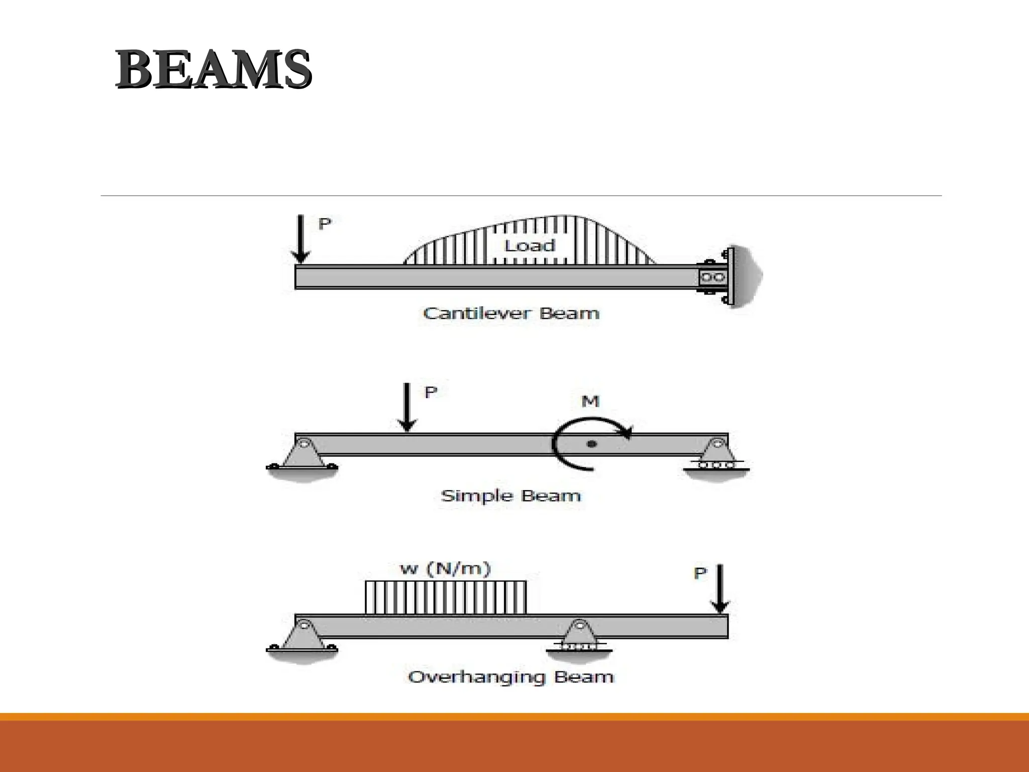
Statically Determinate Beams
Statically determinate beams are those beams in
which the reactions of the supports may be
determined by the use of the equations of static
equilibrium. The beams shown below are
examples of statically determinate beams.
BEAMS
BEAMS
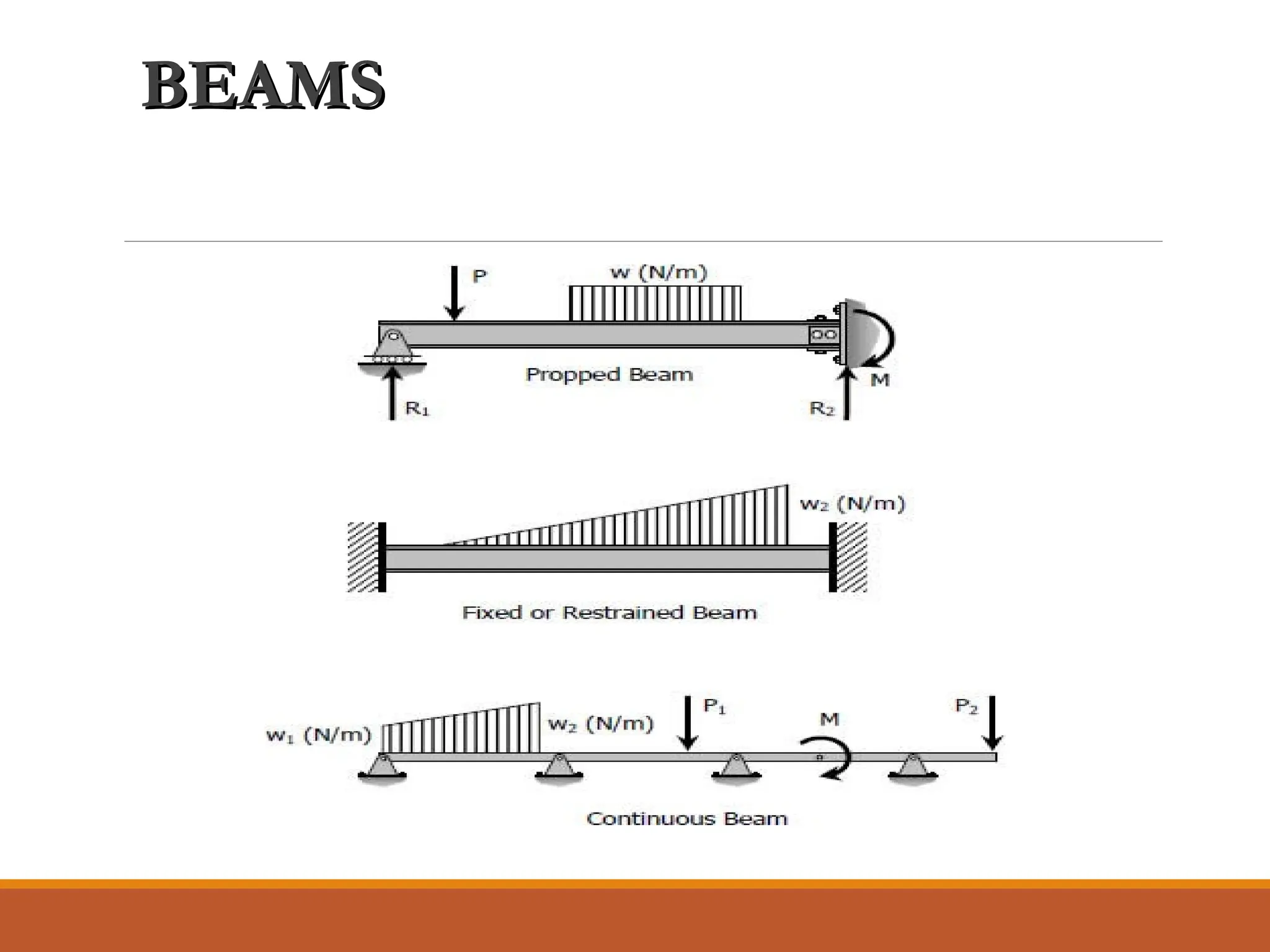
Statically Indeterminate Beams
Ifthe number of reactions exerted upon a beam exceeds
the number of equations in static equilibrium, the beam is
said to be statically indeterminate. In order to solve the
reactions of the beam, the static equations must be
supplemented by equations based upon the elastic
deformations of the beam.
The degree of indeterminacy is taken as the difference
between the number of reactions to the number of
equations in static equilibrium that can be applied. In the
case of the propped beam shown, there are three
reactions R1, R2, and M and only two equations (ΣM = 0
and ΣFv = 0) can be applied, thus the beam is
indeterminate to the first degree (3 - 2 = 1).
LOADINGS
LOADINGS
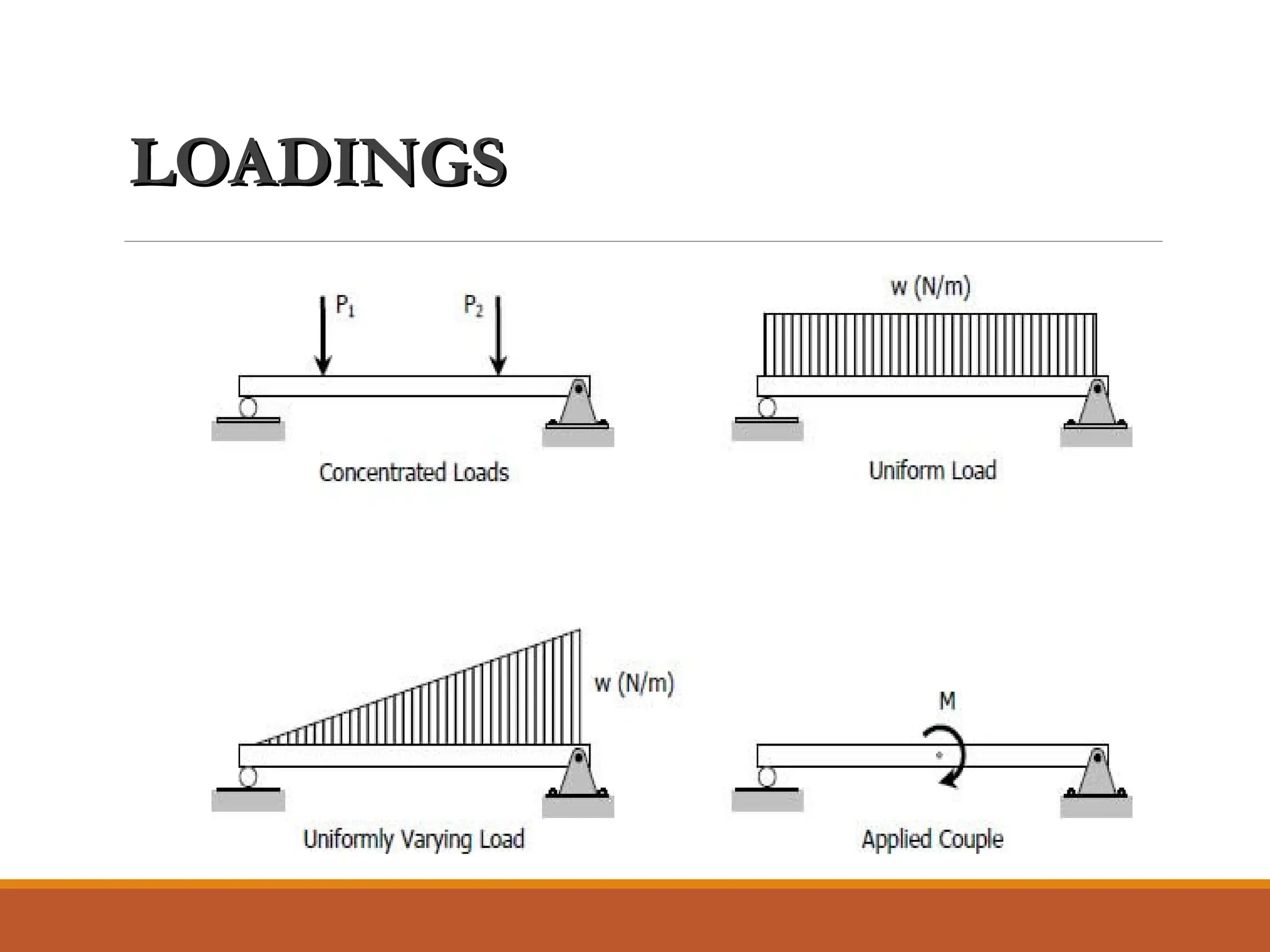
Types of Loading
•Concentrated Load – acts at a point on the beam
•Distributed Load – acts over a length of the beam
•Concentrated Moments - tends to bend and
rotate the beam
SHEAR AND MOMENTDIAGRAM
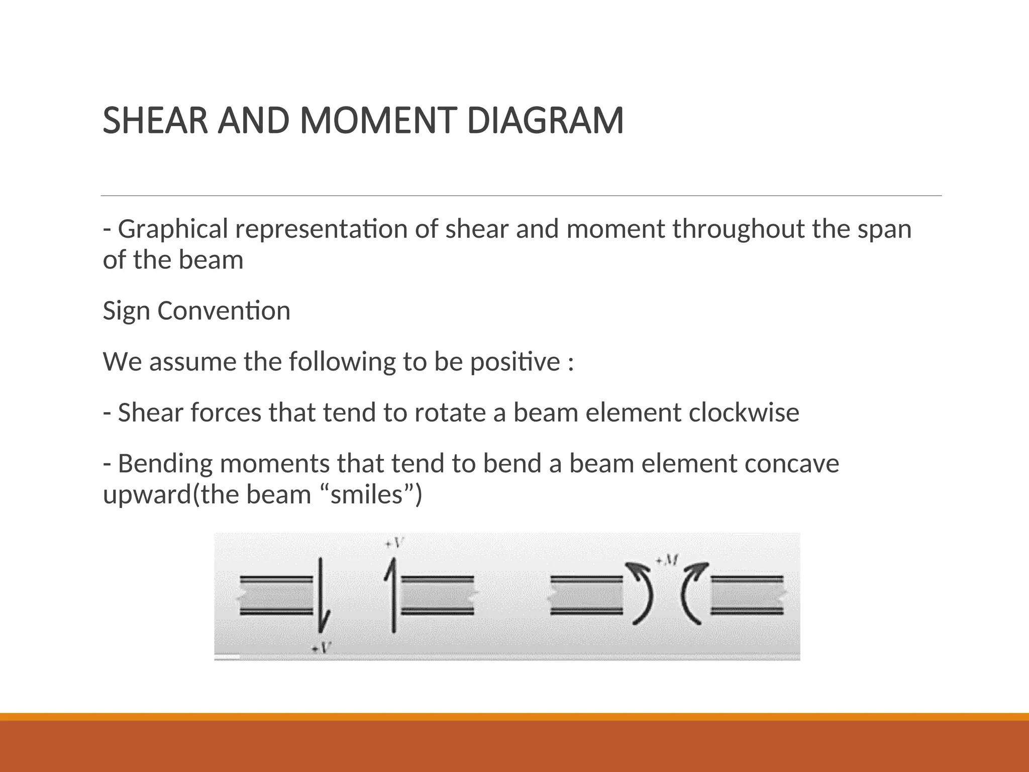
- Graphical representation of shear and moment throughout the span
of the beam
Sign Convention
We assume the following to be positive :
- Shear forces that tend to rotate a beam element clockwise
- Bending moments that tend to bend a beam element concave
upward(the beam “smiles”)
9.
SHEAR AND MOMENTDIAGRAM
Method of Section – V and M as functions of x for
each segment of the beam between a change in
loading point or discontinuity in loading.
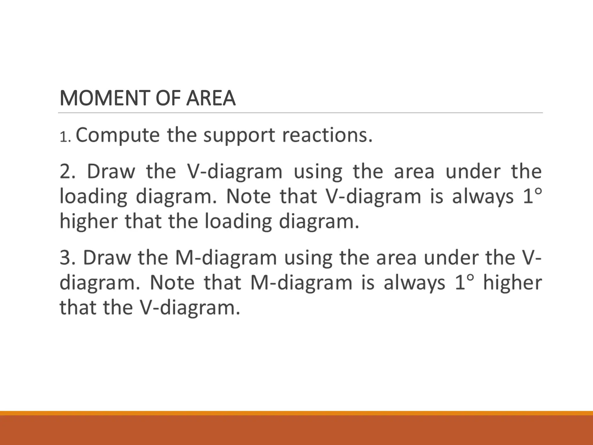
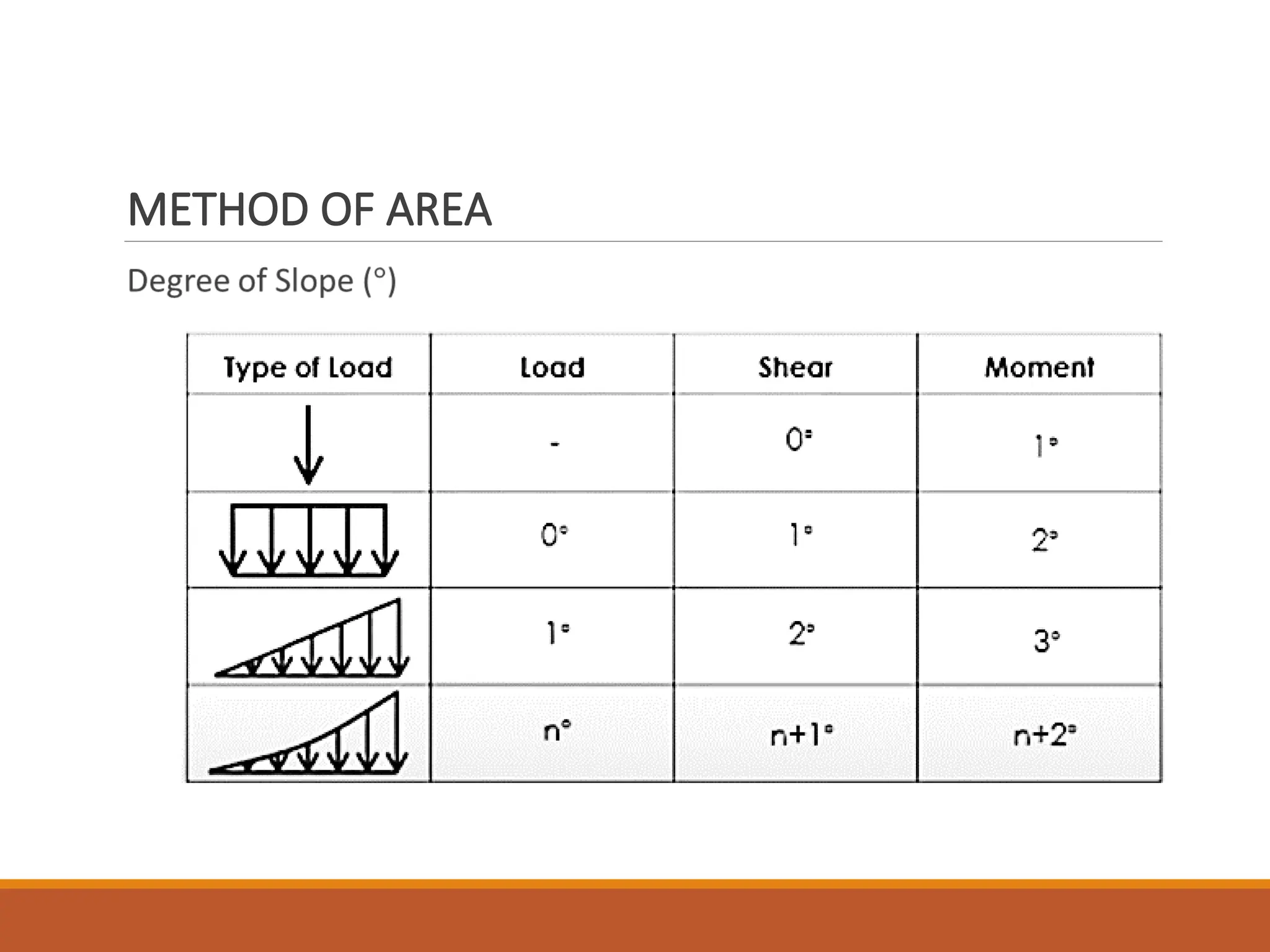
Method of Area – change in shear equals the area
under loading diagram and change in moment
equals the area under the shear diagram.
10.
METHOD OF SECTION
1.Compute the support reactions.
2. Divide the beam into segments so that loading in each segment is
continuous.
3. Introduce a cutting plane within the segment, located at x distance
from the left end of the beam, that cuts the beam into two parts.
4. Choose a section to consider, whichever is more convenient. At the
cut section, show V and M acting in their positive directions.
5. Determine the expressions for V and M as a function of x using
equations of equilibrium.
6. Plot the expressions for V and M for the segment. It is visually
desirable to draw the V-diagram below the FBD of the entire beam, an
then draw the M-diagram below the V-diagram.
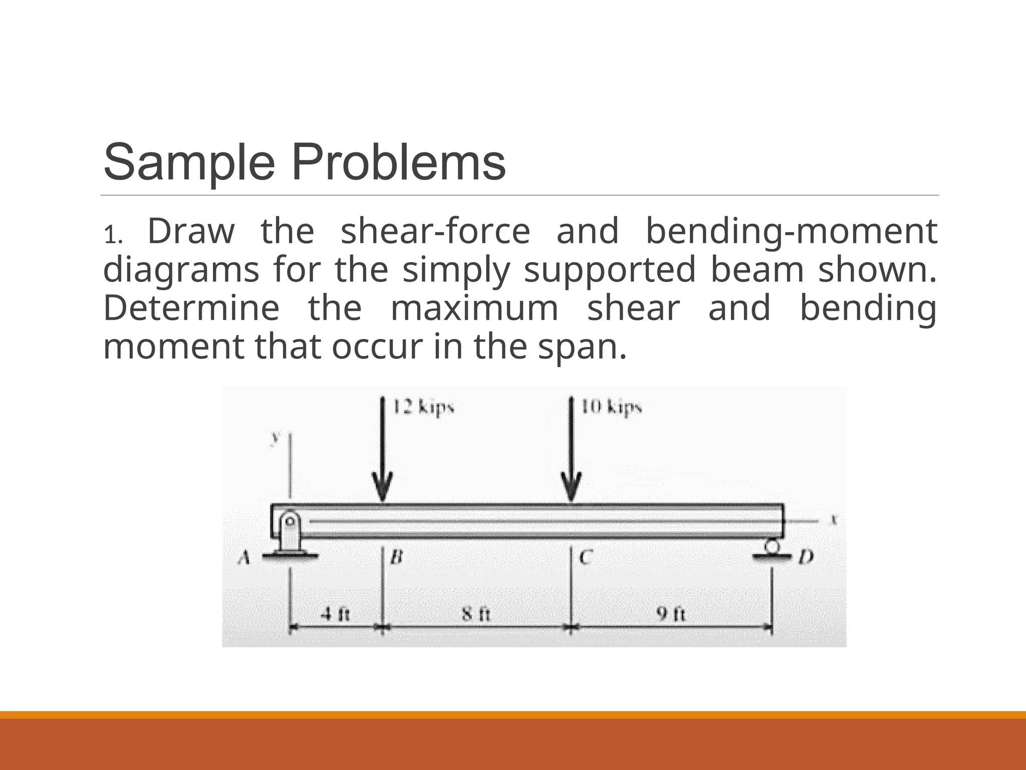
Sample Problems
1. Drawthe shear-force and bending-moment
diagrams for the simply supported beam shown.
Determine the maximum shear and bending
moment that occur in the span.
15.
Sample Problems
2. Drawthe shear-force and bending-moment
diagrams for the simply supported beam.
Determine the maximum shear and bending
moment that occur in the span.
16.
Sample Problems
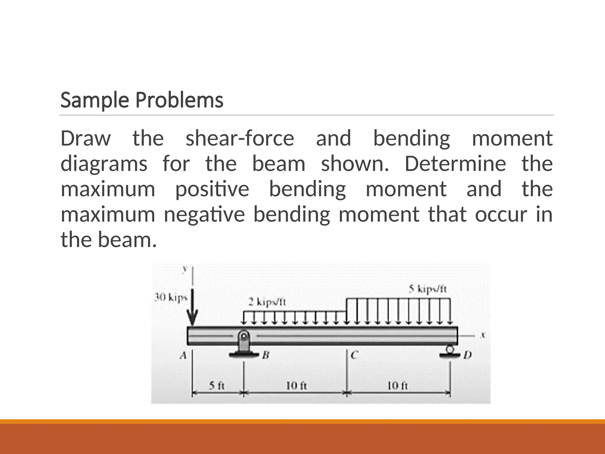
Draw theshear-force and bending moment
diagrams for the beam shown. Determine the
maximum positive bending moment and the
maximum negative bending moment that occur in
the beam.
17.
Sample Problems
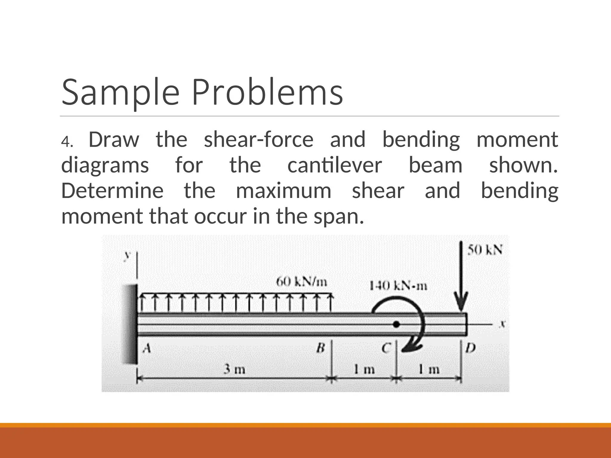
4. Drawthe shear-force and bending moment
diagrams for the cantilever beam shown.
Determine the maximum shear and bending
moment that occur in the span.
18.
Sample Problems
5. Drawthe shear-force and bending moment
diagrams for the overhanging beam shown.
Determine the (a) maximum shear, (b) maximum
positive and maximum negative bending moment
that occur in the beam.
19.
Sample Problems
6. Drawthe shear-force and bending –moment
diagrams for the simply supported beam shown.
Determine the maximum shear and bending
moment that occur in the span.