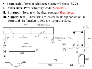
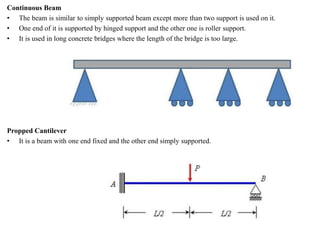
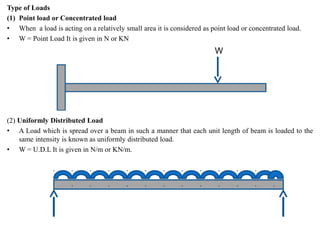
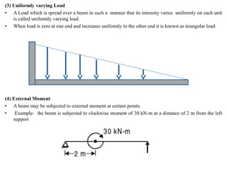
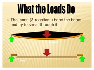
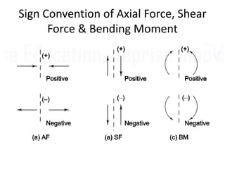
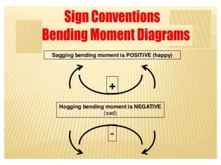
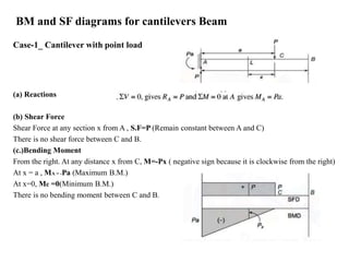
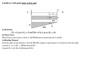
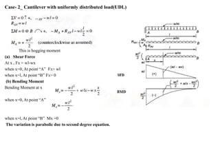
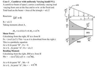
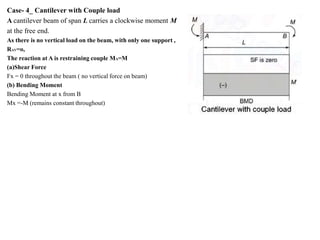
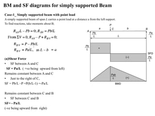
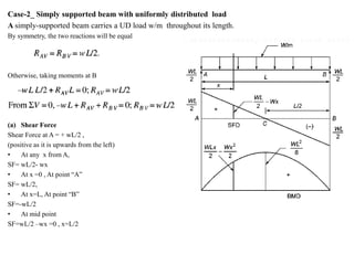
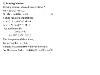
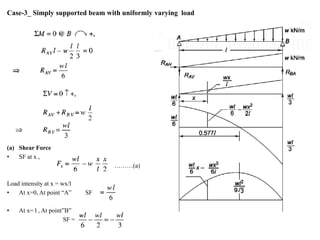
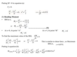
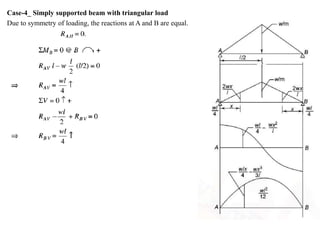
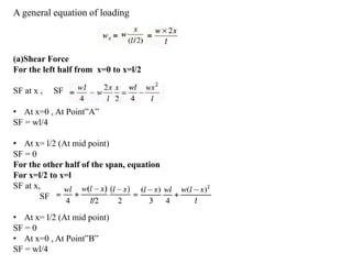
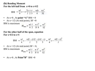
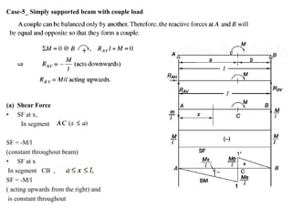
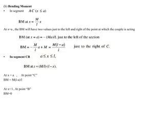
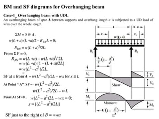
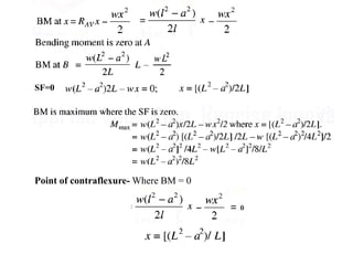
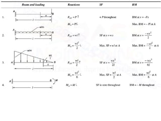
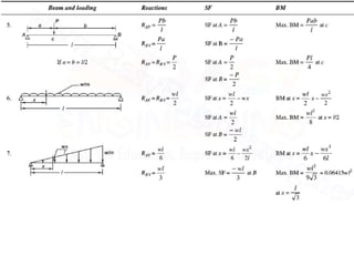
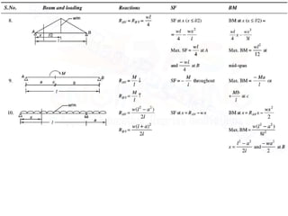
Mr. Akash provides a 3-page document summarizing bending moment and shear force diagrams for various beam types including cantilevers, simply supported beams, overhanging beams, and continuous beams. The document defines key terms like shear force, bending moment, point load, uniformly distributed load, and point of contraflexure. It then provides examples of calculating reactions, shear forces, and bending moments for each beam type under different loading conditions such as a point load, uniform load, or varying load. Diagrams are included to illustrate the variations in shear force and bending moment.
Mr. Akash
Assistant Professor
Departmentof Civil Engineering
DCE Darbhanga
Module- 3
Bending moment and
Shear Force Diagrams
Part-1
Introduction to
Solid Mechanics
Course Code- 101205
2.
Syllabus
Bending moment andShear Force Diagrams
• BM and SF diagrams for cantilevers, simply supported and fixed beams with or without
overhangs. Calculation of maximum BM and SF and the point of contra flexure under
concentrated loads, uniformly distributed loads over the whole span or part of span,
combination of concentrated loads (two or three) and uniformly distributed loads, uniformly
varying loads, application of moments.
3.
Beam
• A beamis a horizontal structural member in a building to resist
the lateral loads or resists the forces laterally or transversely
applied to the (beam) axis.
Slab |> Beam |> Column |> Foundation
4.
• A structuralelement which has one dimension considerably larger than the
other two dimensions, namely breadth and depth, and is supported at few points.
Purpose of Beam
I. Resist loads
II. Counter bending moment and shear forces.
III. Connect the structure together.
IV. Provide a uniform distribution of loads.
• The total effect of all the forces acting on the beam to produce shear forces and
bending moment within the beam, that in turn induce internal stresses, strains and
deflections of the beam.
5.
• Beam madeof steel or reinforced concrete Cement (RCC)
I. Main Bars– Provide to carry loads (Moments).
II. Stirrups – To counter the shear stresses (Shear force).
III. Support bars – These bars are located in the top portion of the
beam and just function to hold the stirrups in place.
B1
B2
T1
S1
6.
• The reactionsdepend upon the type of supports and type of loading
Support:
• A thing that bears the weight of something or keeps it upright.
• A beam has to be supported at different points by supports to
withstand loads transmitted to it.
• There are different kinds of supports used to support a beam.
1. Simple Support
2. Hinged/Pinned/Pivoted Support
3. Roller or Knife Edge Support
4. Fixed(Build-in) Support
7.
Simple Support
• WhenBeam placed on simple surface.
• There is connection between beam and support.
• Only vertical reaction will be produced.
• Simple supports are idealized by some to be frictionless surface
supports
8.
Hinged support
• Hingedsupport or pinned support can resist forces in any direction but it does not
resist moments.
• There will be two reaction at the support.
Roller Support
• Roller support can resist forces only in one direction irrespective of the loads
transmitted to the support.
• Nos. of reaction is one and the direction of the resisting force is always
perpendicular to the base of the support.
9.
Fixed support
• Abeam with firmly fixed end preventing any kind of movements
and rotation is considered as a fixed support.
• Fixed support resists movement of the beam in any direction and
also it prevents the rotation of the beam. Hence it can resist forces
in any direction and also it can resist moments (resists rotation).
10.
Types of Beam
Basedon equilibrium conditions:
• Statically determinate beam – Statically determinate structures
are structures that can be analyzed using statics equations only, (i.e.,
equilibrium in all directions).
• Statically indeterminate beam– Statically indeterminate
structures can't be analyzed using statics equations only; they require
other material properties, such as deformations, in order to analyze
them.
Based on the type of support:
• Simply supported beam
• Cantilever beam
• Overhanging beam
• Fixed beam
• Continuous beam
11.
Simply Supported Beam
•A simply supported beam is a type of beam that has pinned support at one end and roller support at the
other end.
• Depending on the load applied, it undergoes shearing and bending.
• It is the one of the simplest structural elements in existence.
Cantilever Beam
• Cantilever beams a structure member of which one end is fixed and other is free.
• This is one of the famous type of beam used in trusses, bridges etc.
12.
Overhanging Beam
• Theoverhanging beam is a combination of simply supported beam and a cantilever beam, so has
heritage properties of the cantilever and simply supported beam.
• One or both of end overhang of this beam.
• The beam is supported by roller support between two ends.
Fixed Beam
• The beam is fixed from both ends.
• It does not allow vertical movement.
• It is only under the shear no moment produces in these beams.
• It is used in trusses.
13.
Continuous Beam
• Thebeam is similar to simply supported beam except more than two support is used on it.
• One end of it is supported by hinged support and the other one is roller support.
• It is used in long concrete bridges where the length of the bridge is too large.
Propped Cantilever
• It is a beam with one end fixed and the other end simply supported.
14.
Type of Loads
(1)Point load or Concentrated load
• When a load is acting on a relatively small area it is considered as point load or concentrated load.
• W = Point Load It is given in N or KN
(2) Uniformly Distributed Load
• A Load which is spread over a beam in such a manner that each unit length of beam is loaded to the
same intensity is known as uniformly distributed load.
• W = U.D.L It is given in N/m or KN/m.
15.
(3) Uniformly varyingLoad
• A Load which is spread over a beam in such a manner that its intensity varies uniformly on each unit
is called uniformly varying load.
• When load is zero at one end and increases uniformly to the other end it is known as triangular load.
(4) External Moment
• A beam may be subjected to external moment at certain points.
• Example- the beam is subjected to clockwise moment of 30 kN-m at a distance of 2 m from the left
support
20.
Axial force thrust
•The axial force (AF) at any section of a beam is equal to the algebraic sum of the forces parallel to the
axis of the beam either to the left or the right of the section.
Shear force
• The shear force (SF) at any section of a beam is equal to the algebraic sum of the forces perpendicular
to the axis of the beam either to the left or the right of the section.
• Shear Forces occurs when two parallel forces act out of alignment with each other.
• For example, in a large boiler made from sections of sheet metal plate riveted together, there is an
equal and opposite force exerted on the rivets, owing to the expansion and contraction of the plates.
Bending moment
• The bending moment (BM) at any section of a beam is equal to the algebraic sum of the moments of
all the forces, either to the left or to the right of the section, about the section.
• At any point within a beam, the Bending Moment is the sum of each external force multiplied by the
distance that is perpendicular to the direction of the force.
• Bending Moments are rotational forces within the beam that cause bending.
BM and SFdiagrams for cantilevers Beam
Case-1_ Cantilever with point load
(a) Reactions
(b) Shear Force
Shear Force at any section x from A , S.F=P (Remain constant between A and C)
There is no shear force between C and B.
(c.)Bending Moment
From the right. At any distance x from C, M=-Px ( negative sign because it is clockwise from the right)
At x = a , MA = -Pa (Maximum B.M.)
At x=0, Mc =0(Minimum B.M.)
There is no bending moment between C and B.
24.
Cantilever with pointload at free end
A B
-
(a) Reactions
(b) Shear Force
Shear Force at any section x from A , S.F=P (Remain constant between A and B)
(c.)Bending Moment
From the right. At any distance x from B, M=-Px ( negative sign because it is clockwise from the right)
At point A (x=l ) MA = -Pl(Maximum B.M.)
At point B ( x=0), MB=0 (Minimum B.M.)
25.
Case- 2_ Cantileverwith uniformly distributed load(UDL)
This is hogging moment
(a) Shear Force
At x , Fx = wl-wx
when x=0, At point “A” FX= wl
when x=l, At point “B” FX= 0
(b) Bending Moment
Bending Moment at x
when x=0, At point “A”
when x=l, At point “B” Mx =0
The variation is parabolic due to second degree equation.
26.
Case-3 _ Cantileverwith uniformly Varying load(UVL)
A cantilever beam of span L carries a uniformly varying load
varying from zero at the free end to w/m at the fixed end.
Total load on the beam = Area of the triangle = wL/2
Reactions
RA= wL/2
Taking moments about A,
Shear Force
Calculating from the right, SF at x from B
Fx = (wx/L)x/2 ( This +ve as it is download from the right.)
This is a parabolic equation.
At x=0 At point “B” , Fx = 0
At x=L , At point “A”, Fx = wL/2
Bending Moment
Calculating from the right, BM at x from B
Mx =
At x=0 At point “B” , Mx = 0
At x=L , At point “A”, Mx = -
27.
Case- 4_ Cantileverwith Couple load
A cantilever beam of span L carries a clockwise moment M
at the free end.
As there is no vertical load on the beam, with only one support ,
RAV=o,
The reaction at A is restraining couple MA=M
(a)Shear Force
Fx = 0 throughout the beam ( no vertical force on beam)
(b) Bending Moment
Bending Moment at x from B
Mx =-M (remains constant throughout)
28.
BM and SFdiagrams for simply supported Beam
Case-1_ Simply supported beam with point load
A simply supported beam of span L carries a point load at a distance a from the left support.
To find reactions, take moments about B;
(a)Shear Force
• SF between A and C
SF = Pa/L ( +ve being upward from left)
Remains constant between A and C
• Just to the right of C,
SF = Pb/L –P =P(b/L-1) =-Pa/L
Remains constant between C and B
• SF between C and B
SF= - Pa/L
(-ve being upward from right)
29.
b) Bending Moment
•.
At x=0 , At point”A” M = 0
At x=a At point “C” M= Pab/L
• .
At x=a , At point”A” M = Pab/L ( This is equation of straight line)
At x=L At point “C” M= 0
30.
Case-2_ Simply supportedbeam with uniformly distributed load
A simply-supported beam carries a UD load w/m throughout its length.
By symmetry, the two reactions will be equal
Otherwise, taking moments at B
(a) Shear Force
Shear Force at A = + wL/2 ,
(positive as it is upwards from the left)
• At any x from A,
SF= wL/2- wx
• At x =0 , At point “A”
SF= wL/2,
• At x=L, At point “B”
SF=-wL/2
• At mid point
SF=wL/2 –wx =0 , x=L/2
31.
b) Bending Moment
Bendingmoment at any distance x from A
Mx = (wL/2) -wx(x/2)
Or, Mx = ……………….(1)
This is equation of parabola.
At x=0 , At point”A” M = 0
At x=L At point “B” M= 0
For maximum BM
This is equation of shear force,
By solving this , x = L/2.
It means Maximum BM will be at the centre.
So, Maximum BM =
32.
Case-3_ Simply supportedbeam with uniformly varying load
(a) Shear Force
• SF at x ,
………(a)
Load intensity at x = wx/l
• At x=0, At point “A” SF
• At x= l , At point”B”
SF =
33.
Putting SF =0in equation (a)
(b) Bending Moment
• BM at x,
…………………………(b)
• At x=0, At point “A” At x=l, At point “B”
To find the maximum value of the BM,
This is similar to shear force , so Maximum
BM at ,
Putting it equation (b)
34.
Case-4_ Simply supportedbeam with triangular load
Due to symmetry of loading, the reactions at A and B are equal.
35.
A general equationof loading
(a)Shear Force
For the left half from x=0 to x=l/2
SF at x , SF
• At x=0 , At Point”A”
SF = wl/4
• At x= l/2 (At mid point)
SF = 0
For the other half of the span, equation
For x=l/2 to x=l
SF at x,
SF
• At x= l/2 (At mid point)
SF = 0
• At x=0 , At Point”B”
SF = wl/4
36.
(b) Bending Moment
Forthe left half from x=0 to x=l/2
BM
• At x=0 , At point “A” BM = 0
• At x= l/2 (At mid point), SF =0
BM is maximum
For the other half of the span, equation
For x=l/2 to x=l
BM
• At x= l/2 (At mid point) SF = 0,
BM is maximum
• At x=0 , At Point”B” BM =0
37.
Case-5_ Simply supportedbeam with couple load
(a) Shear Force
• SF at x,
In segment
SF = -M/l
(constant throughout beam)
• SF at x
In segment CB ,
SF = -M/l
( acting upwards from the right) and
is constant throughout
38.
(b) Bending Moment
•In segment
At x=a , the BM will have two values just to the left and right of the point at which the couple is acting
• In segment CB
At x = a , At point “C”
BM = M(l-a)/l
At x= l , At point “B”
BM=0
39.
BM and SFdiagrams for Overhanging beam
Case-1_ Overhanging beam with UDL
An overhanging beam of span L between supports and overhang length a is subjected to a UD load of
w/m over the whole length.
At Point “ A” SF =
Point At SF=0 ,
Point of contraflexure
•In a beam that is flexing (or bending), the point where there is zero bending moment is called the point of
contraflexure.
• At that point, the direction of bending changes its sign from positive to negative or from negative to
positive. (It may also be thought of as a change from compression to tension or vice versa).