Downloaded 125 times


![10kN
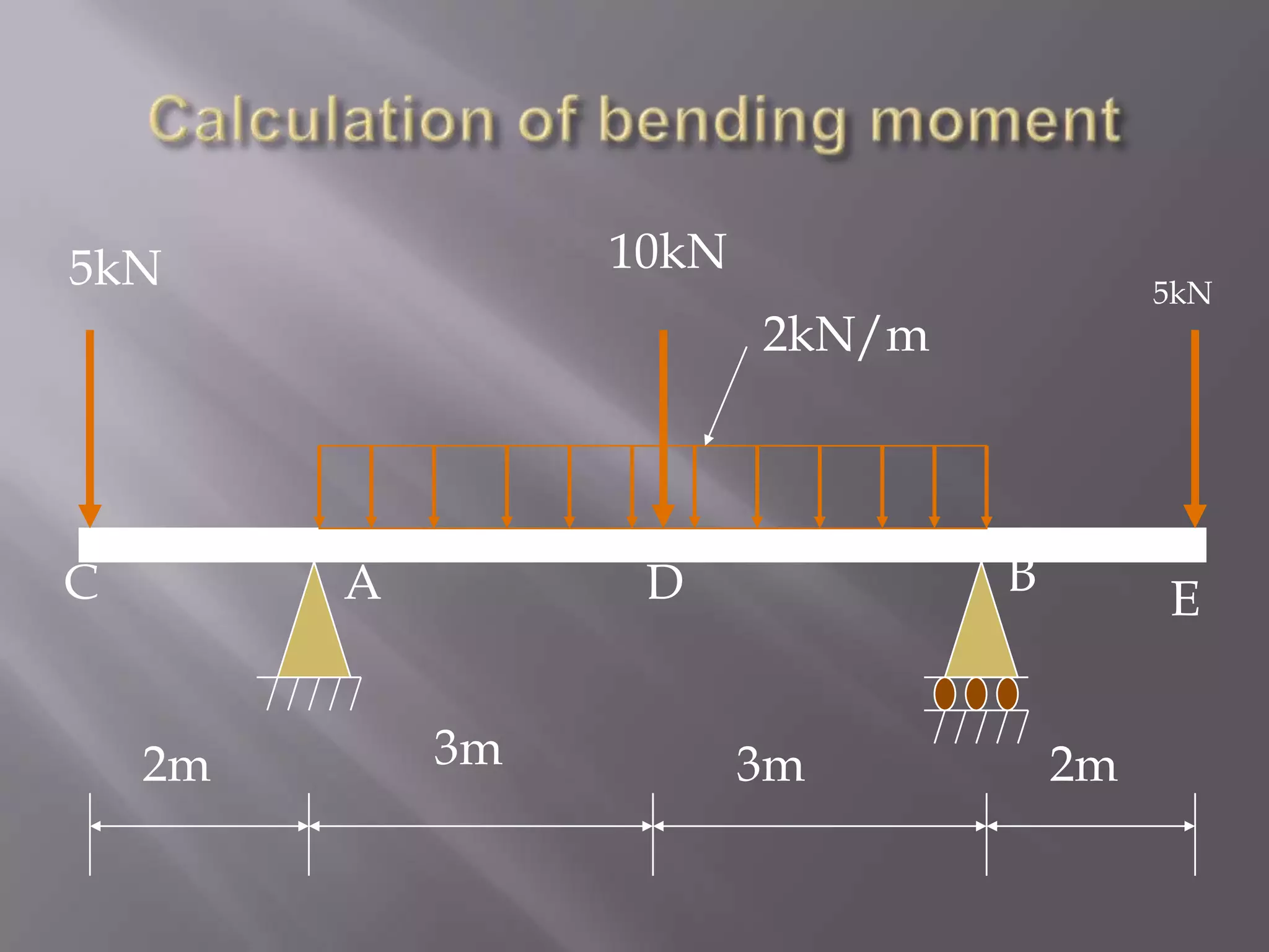
5kN
C
A
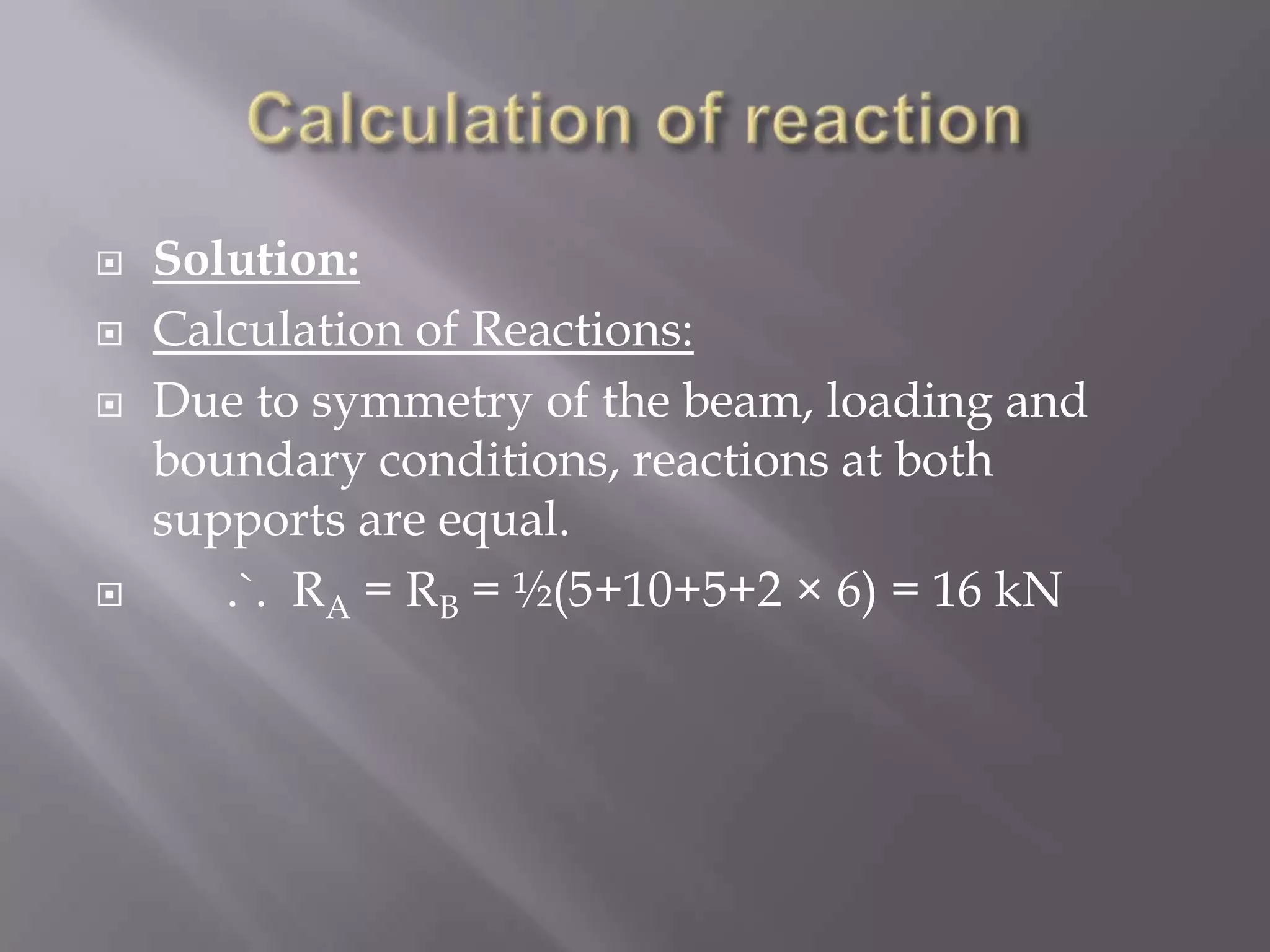
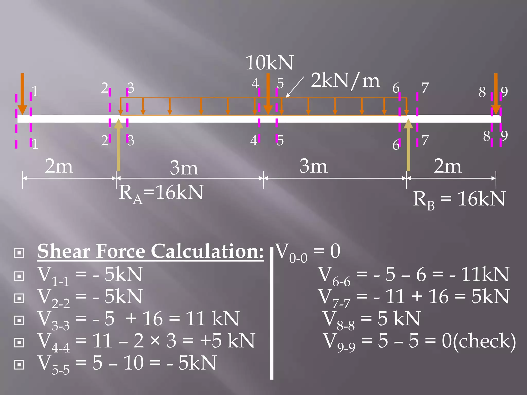
RA=16k
2kN/m
B
D
3m
2m
5kN
3m
E
2m
RB = 16kN
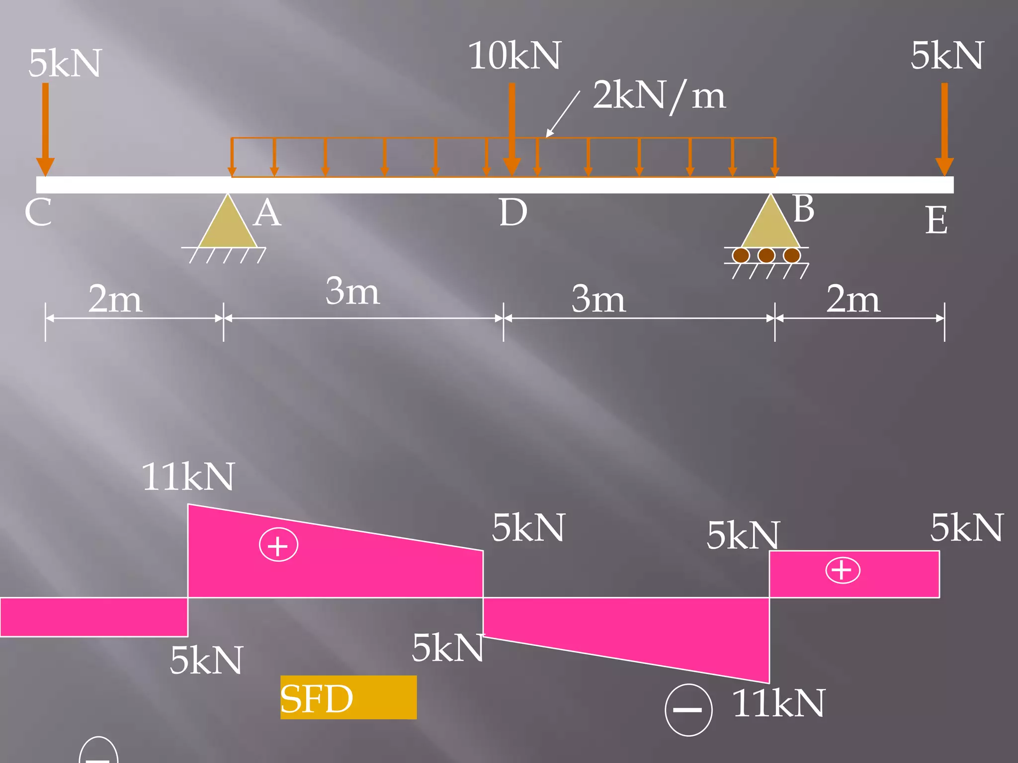
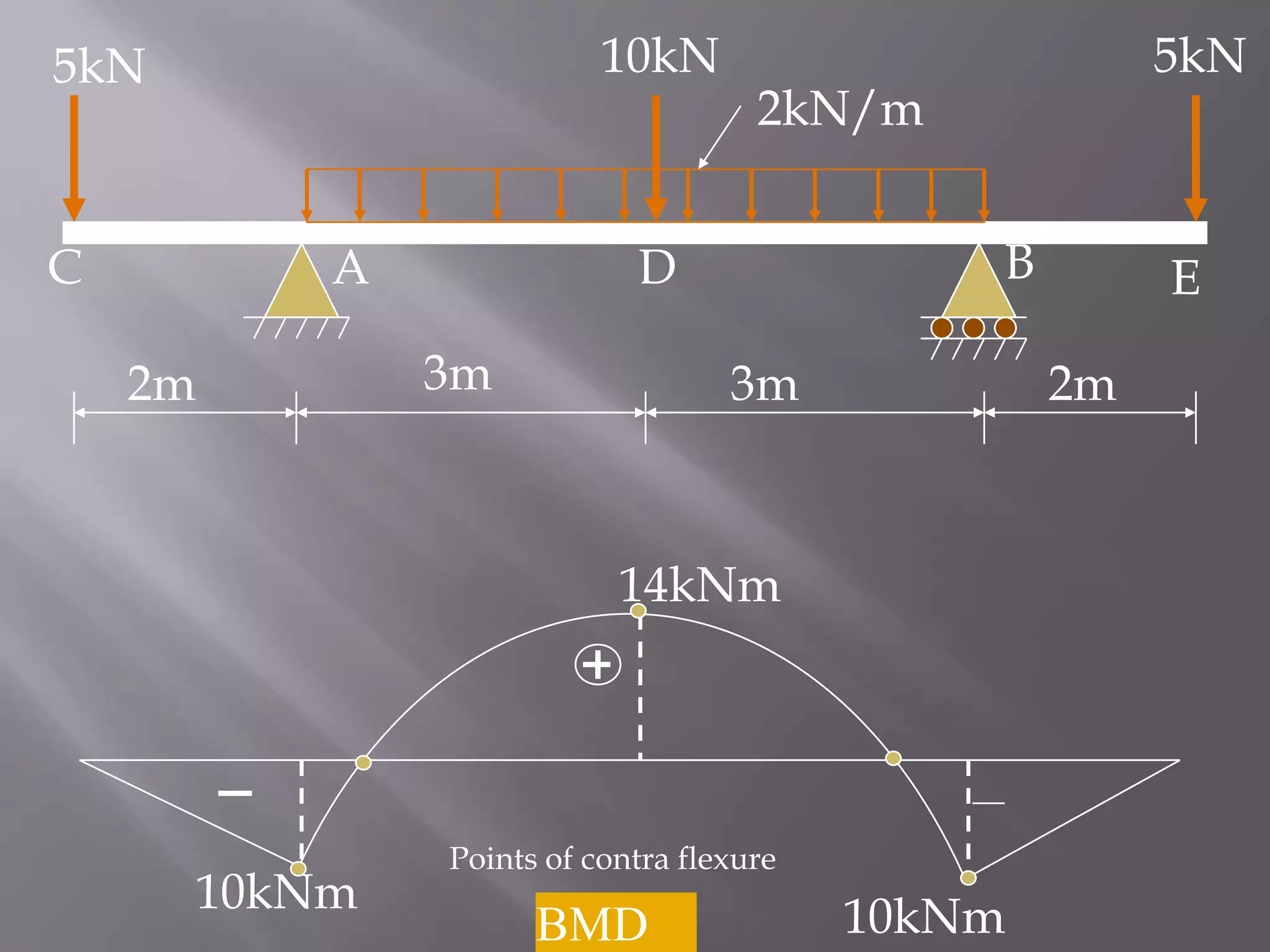
Bending Moment Calculation:
MC = ME = 0 [Because Bending moment at free end is
zero]
MA = MB = - 5 × 2 = - 10 kNm
MD = - 5 × 5 + 16 × 3 – 2 × 3 × 1.5 = +14 kNm](https://image.slidesharecdn.com/presentationonbendingmoment-131201113616-phpapp02/75/Presentation-on-bending-moment-16-2048.jpg)


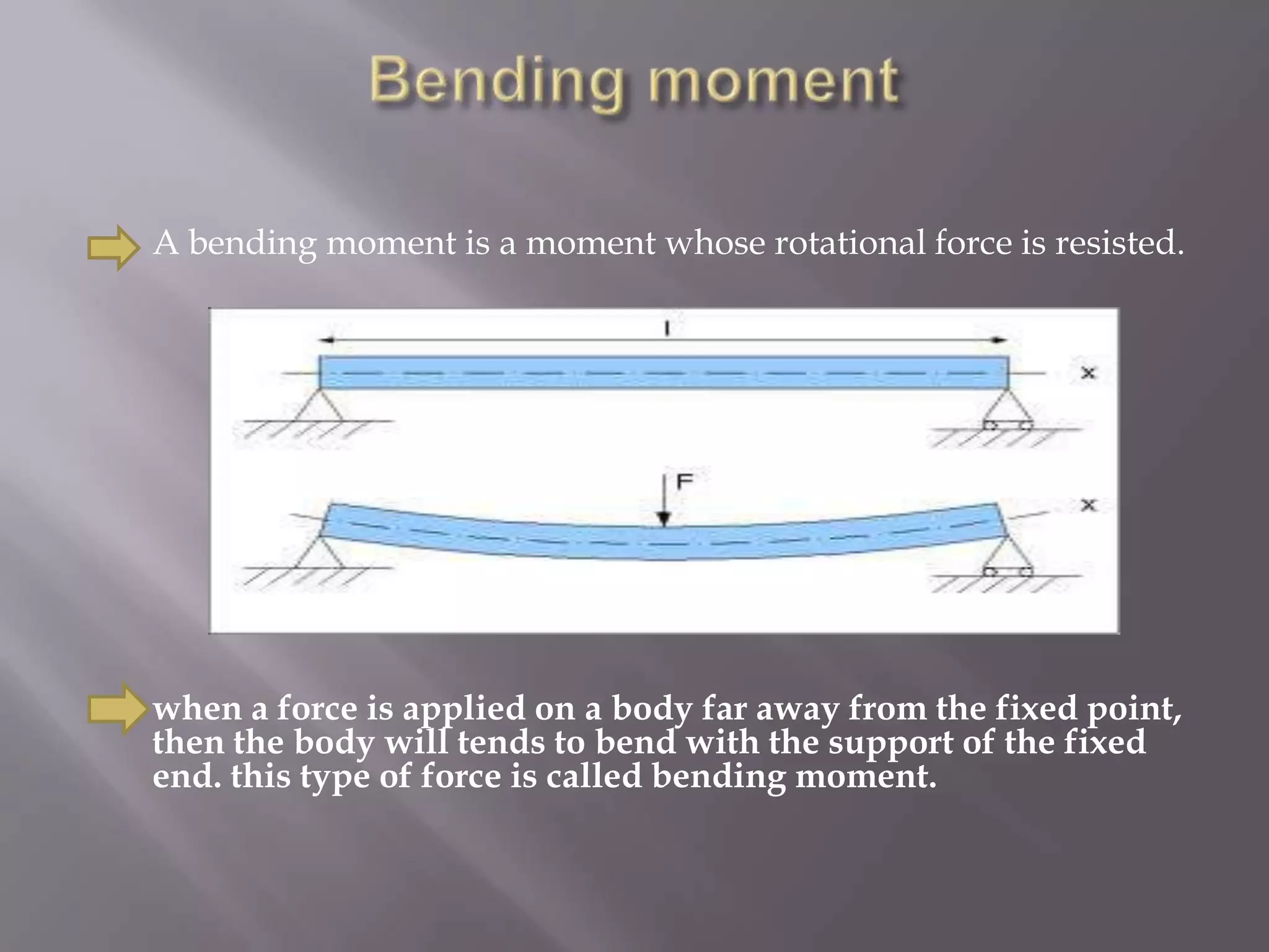
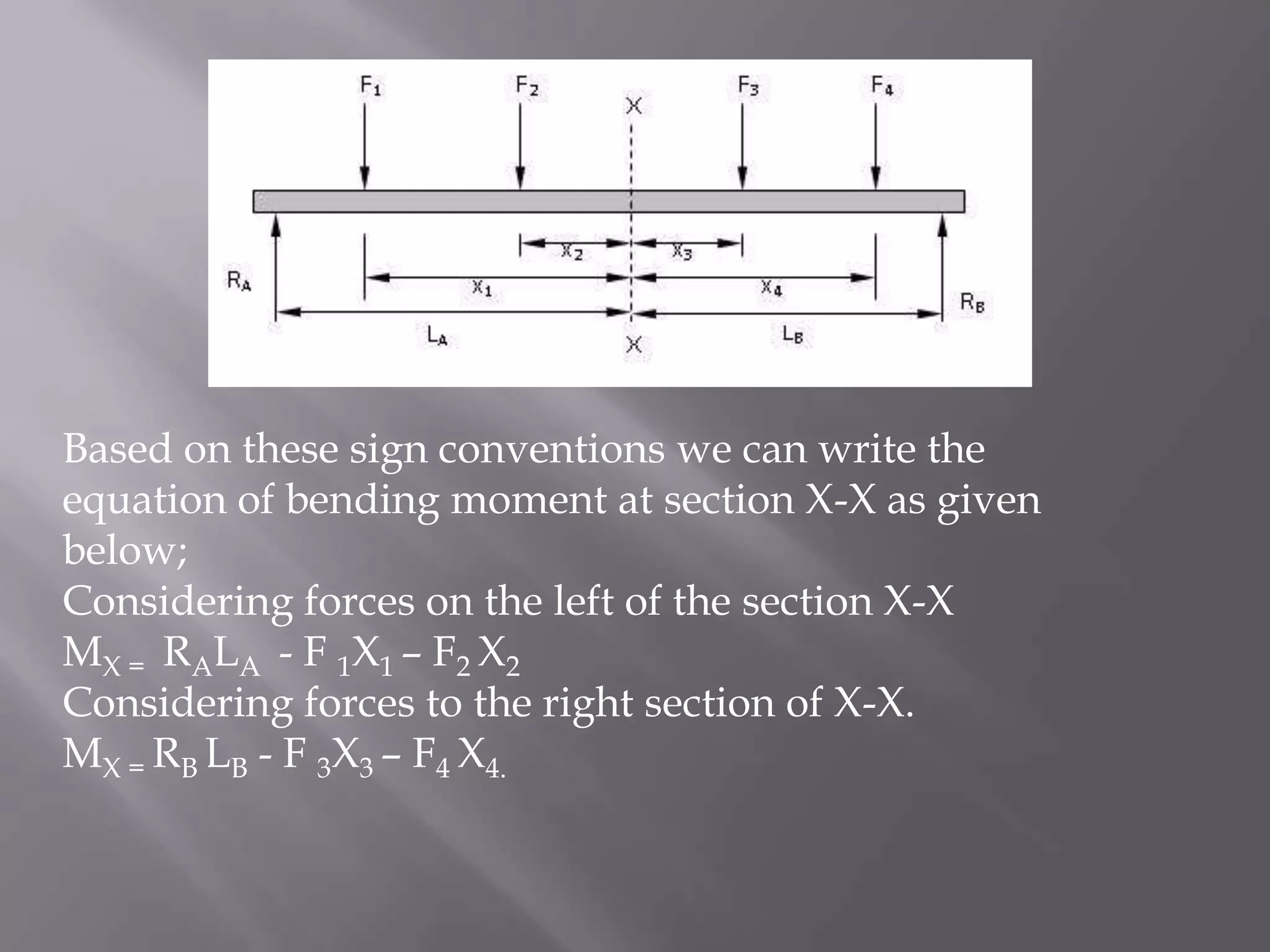
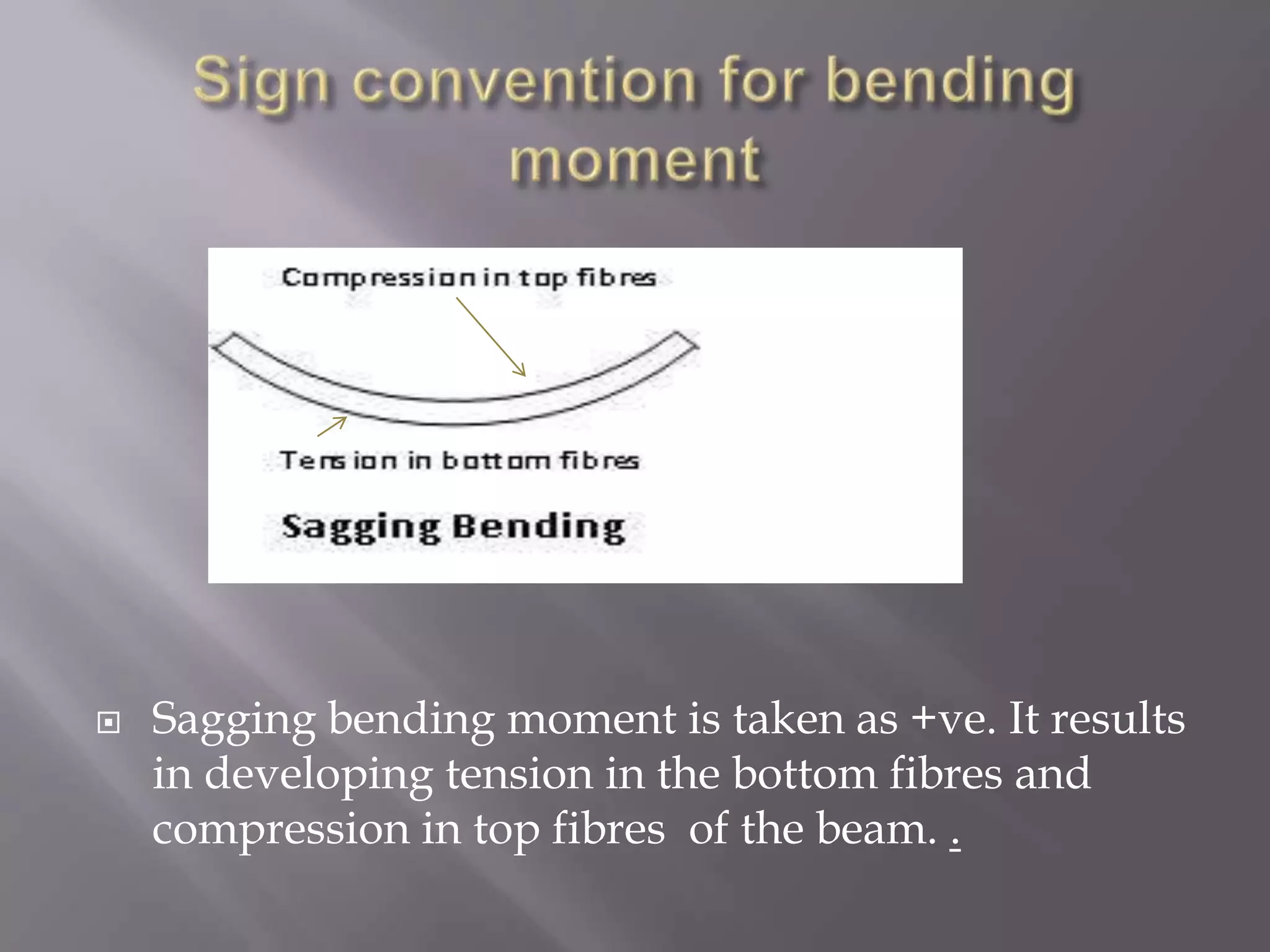
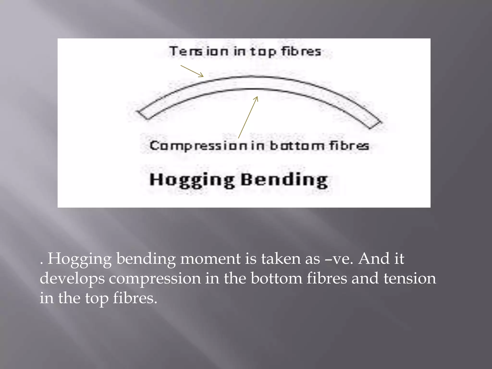
1) Bending moment is a measure of the bending effect on a beam due to applied forces and is measured in units of Newton-meters or foot-pounds force. 2) The bending moment equation is the algebraic sum of the moments about a section of the beam from all forces acting on one side. 3) Positive bending moments cause tension in the bottom fibers and compression in the top fibers (sagging) while negative moments cause the opposite (hogging).


![Vibe Coding vs. Spec-Driven Development [Free Meetup]](https://cdn.slidesharecdn.com/ss_thumbnails/vibecodingvsspecdrivendevelopment-251209105622-43f455e7-thumbnail.jpg?width=640&height=640&fit=bounds)
