Download as PPSX, PPTX
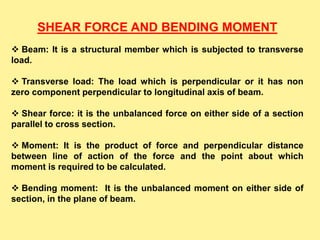
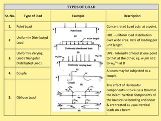
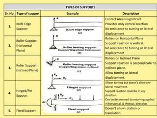
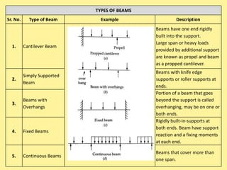
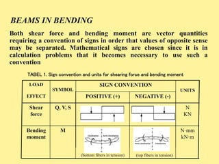
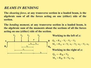
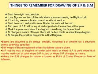
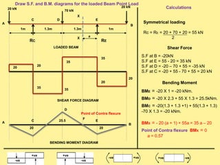

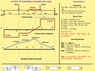
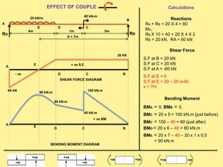
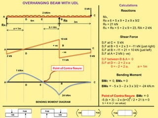
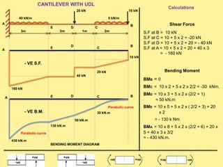
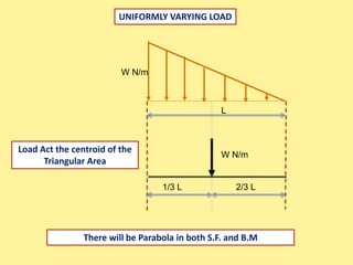

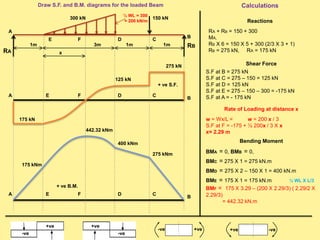
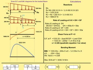
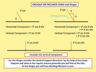
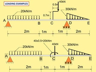


The document discusses shear force and bending moment in beams. It defines key terms like beam, transverse load, shear force, bending moment, and types of loads, supports and beams. It explains how to calculate and draw shear force and bending moment diagrams for different types of loads on beams including point loads, uniformly distributed loads, uniformly varying loads, and loads producing couples or overhangs. Sign conventions and the effect of reactions, loads and geometry on the shear force and bending moment diagrams are also covered.


