Downloaded 1,772 times

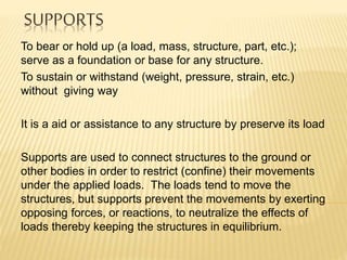
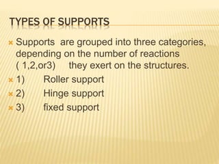
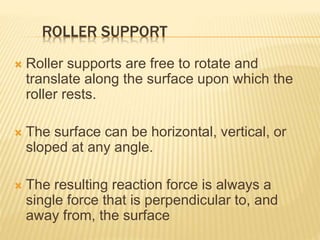

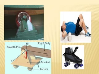
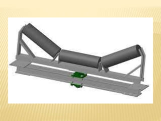


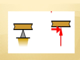
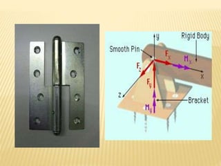
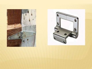
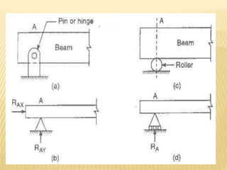


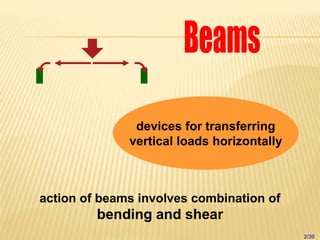

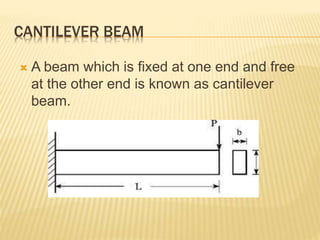

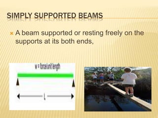

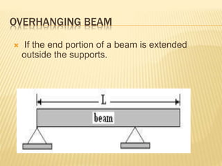


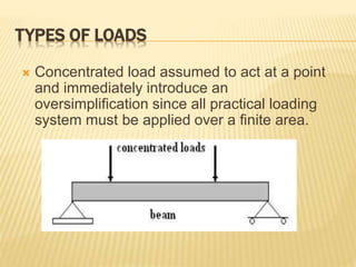

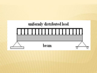
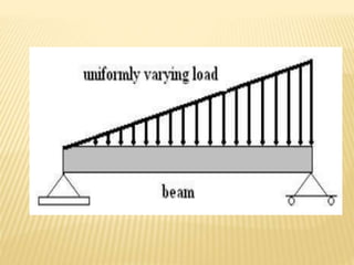
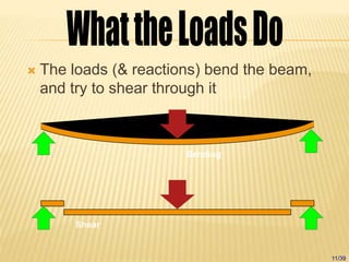


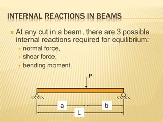
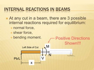


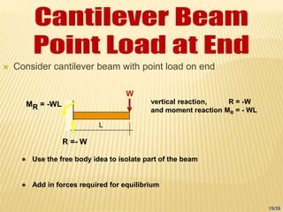

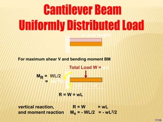


The document discusses beams, which are horizontal structural members that support applied loads. It defines applied and reactive forces, and describes different types of supports including roller, hinge, and fixed supports. It then defines and describes different types of beams, including cantilever, simply supported, overhanging, fixed, and continuous beams. It also discusses types of loads, including concentrated and distributed loads, and how beams experience both bending and shear forces from loads.