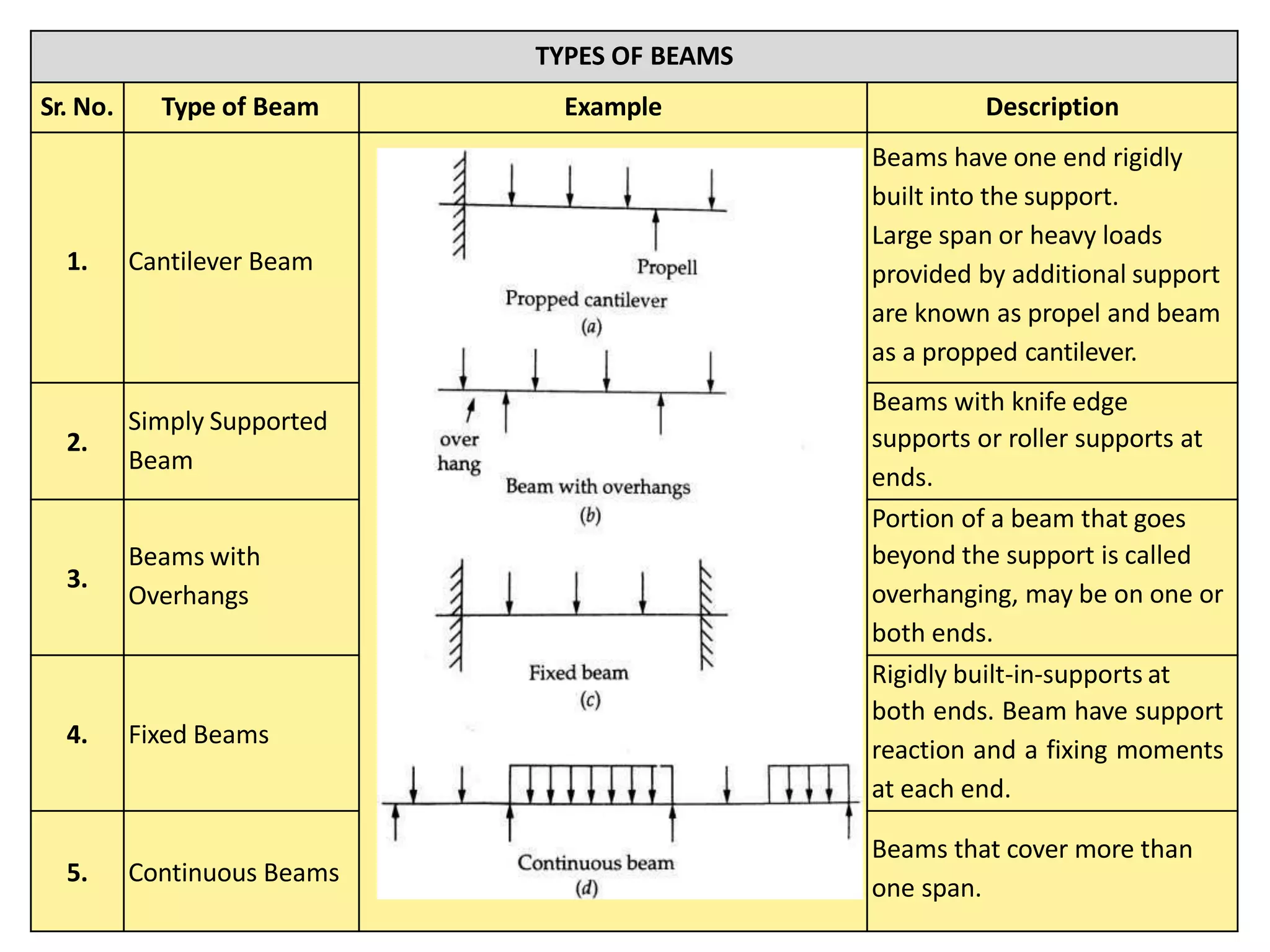
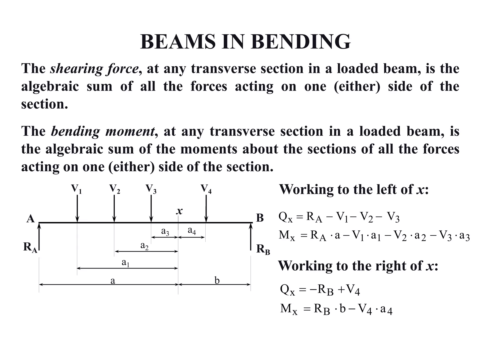
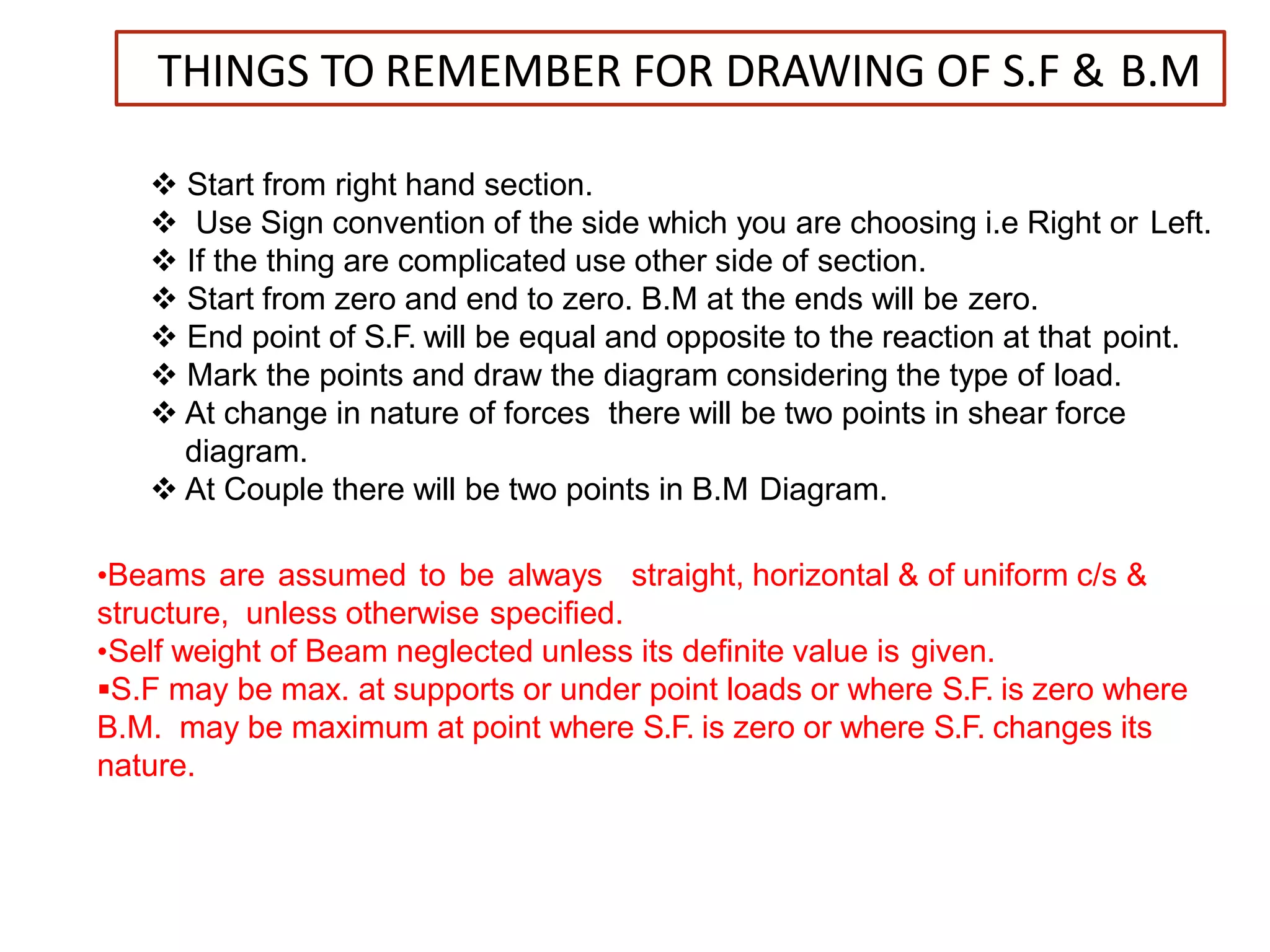
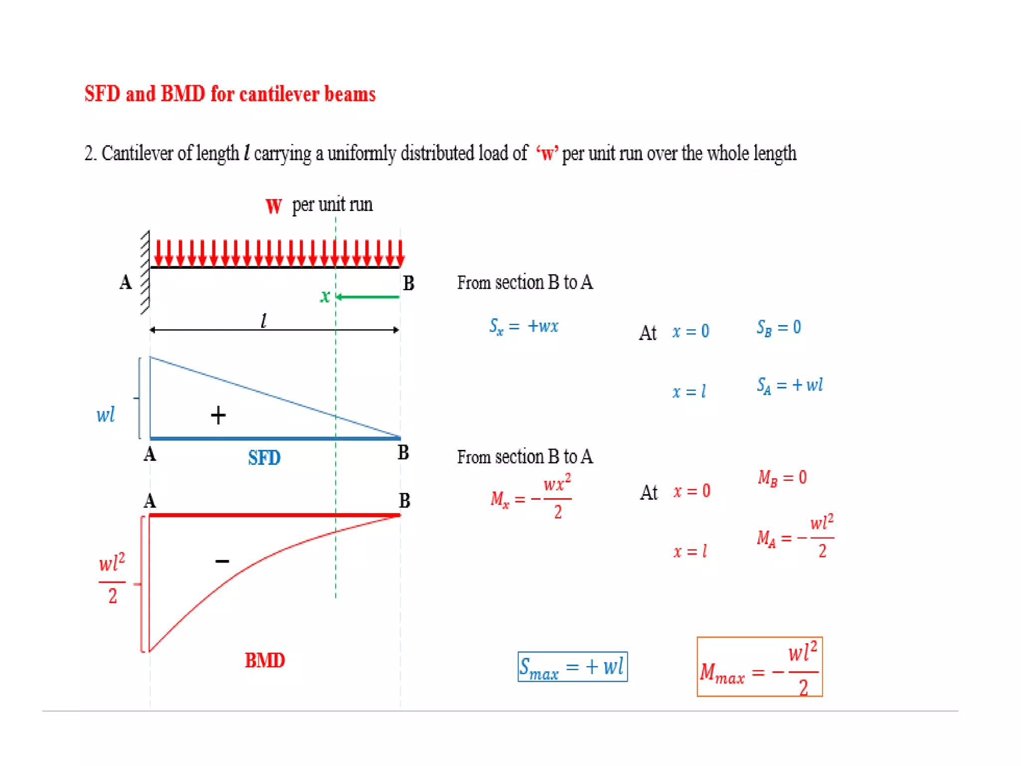
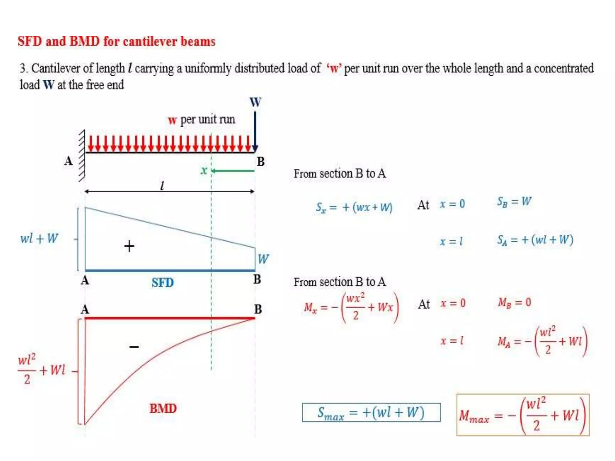
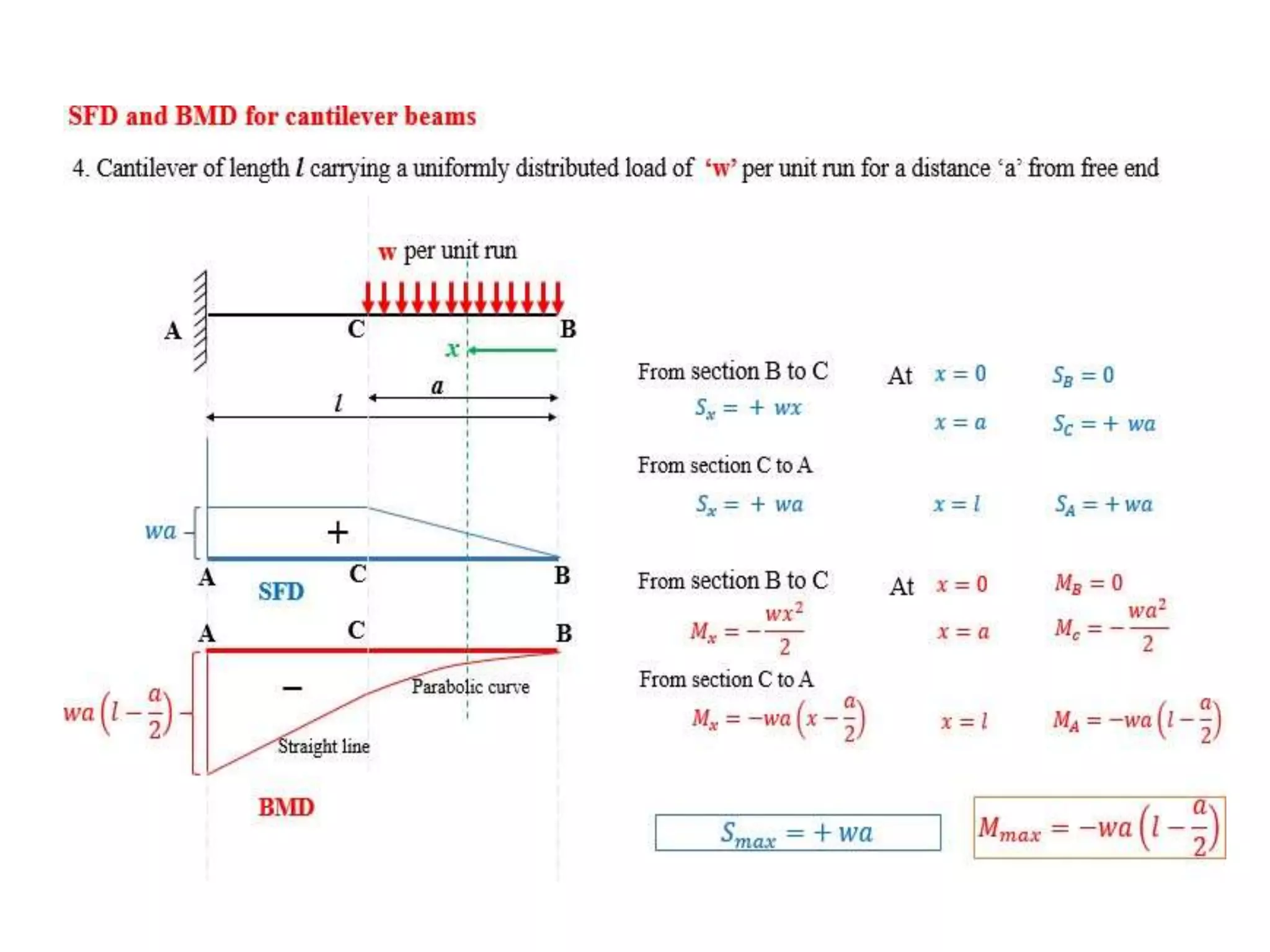
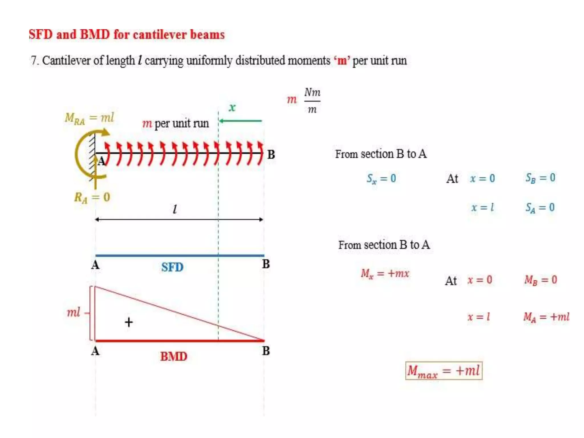
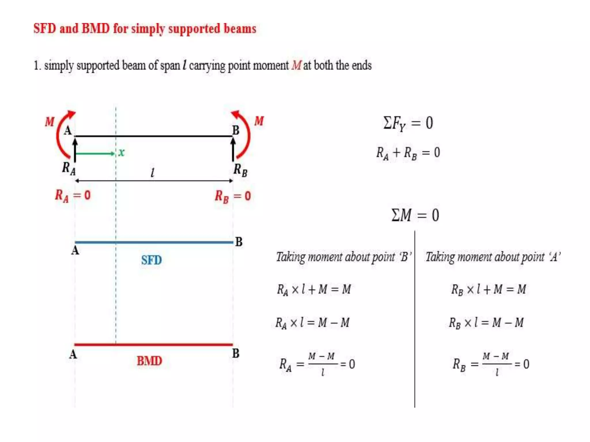
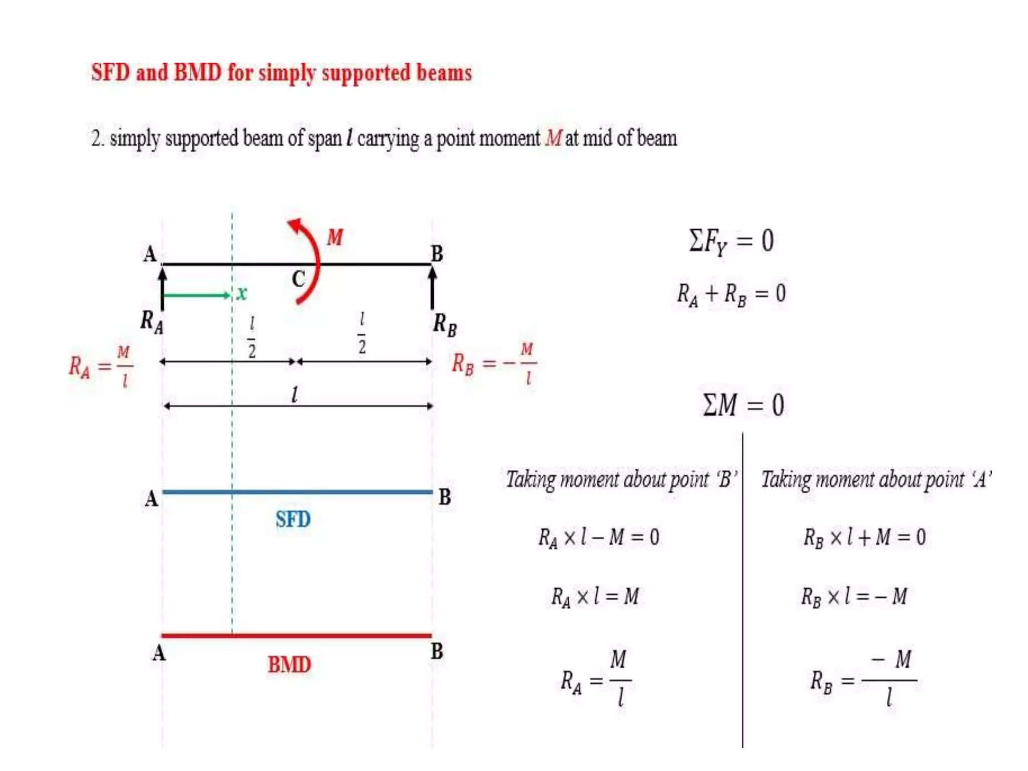
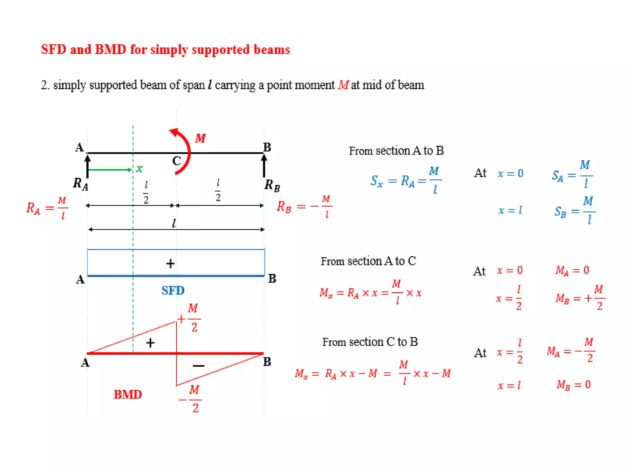
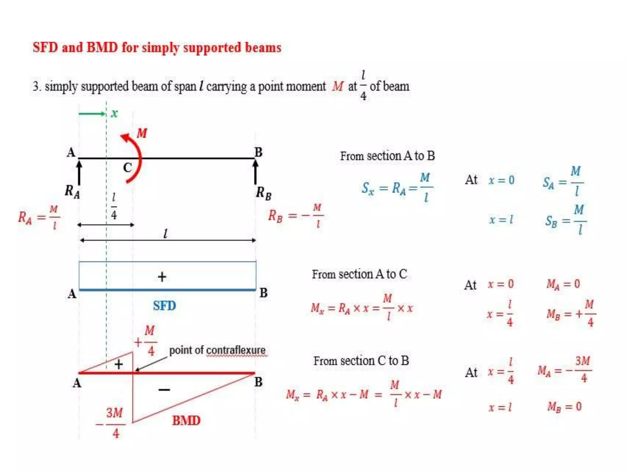
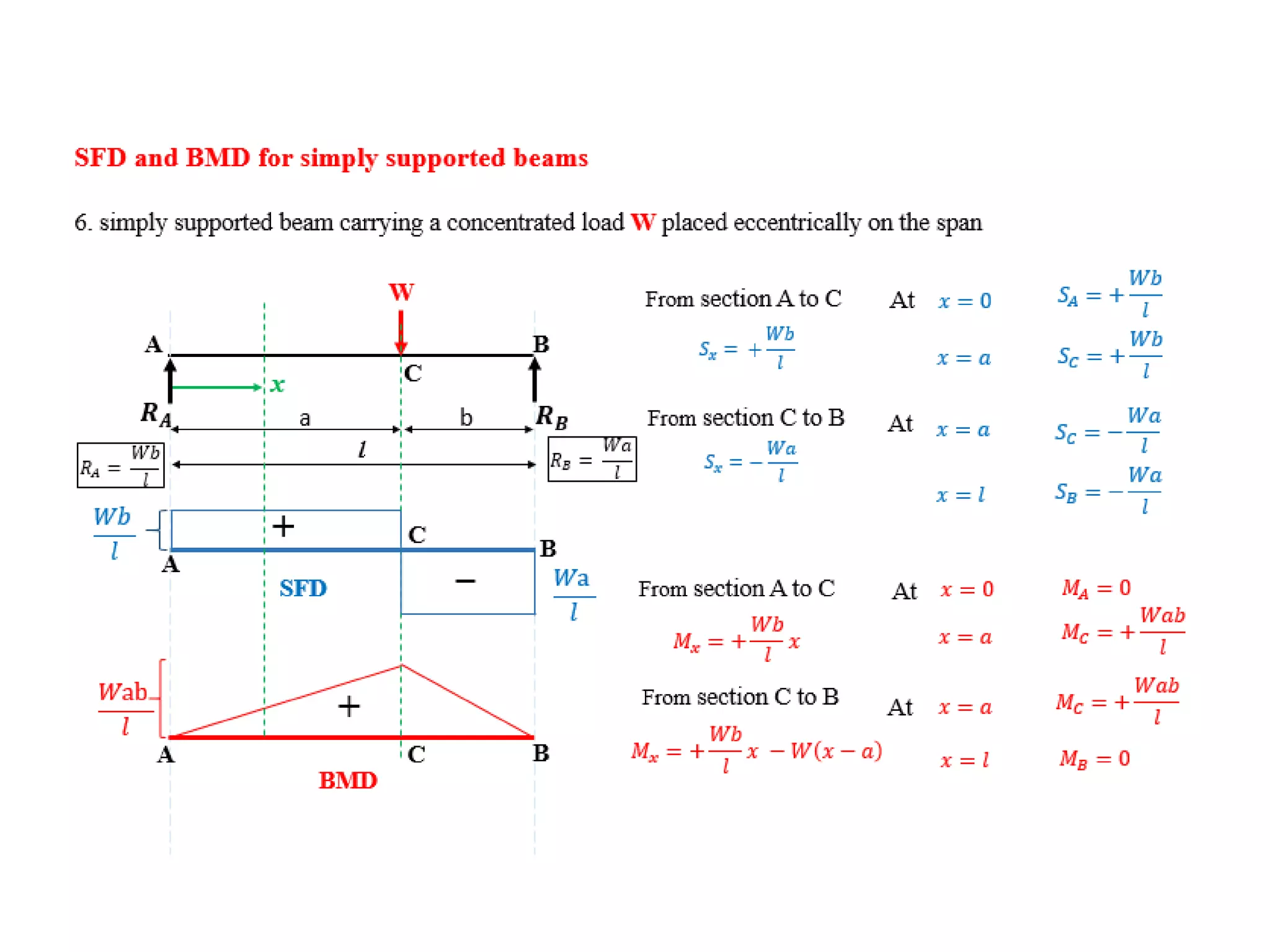
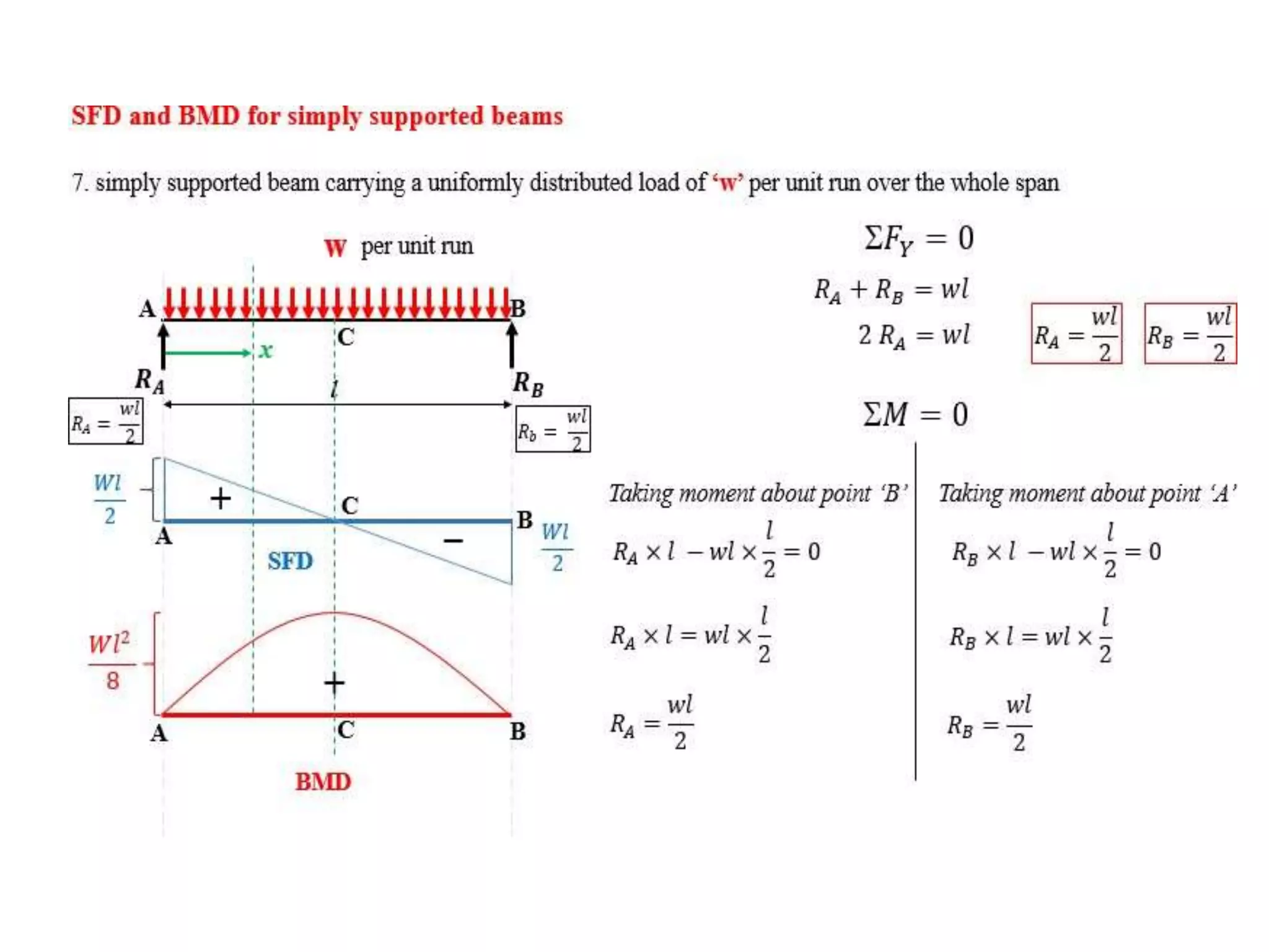
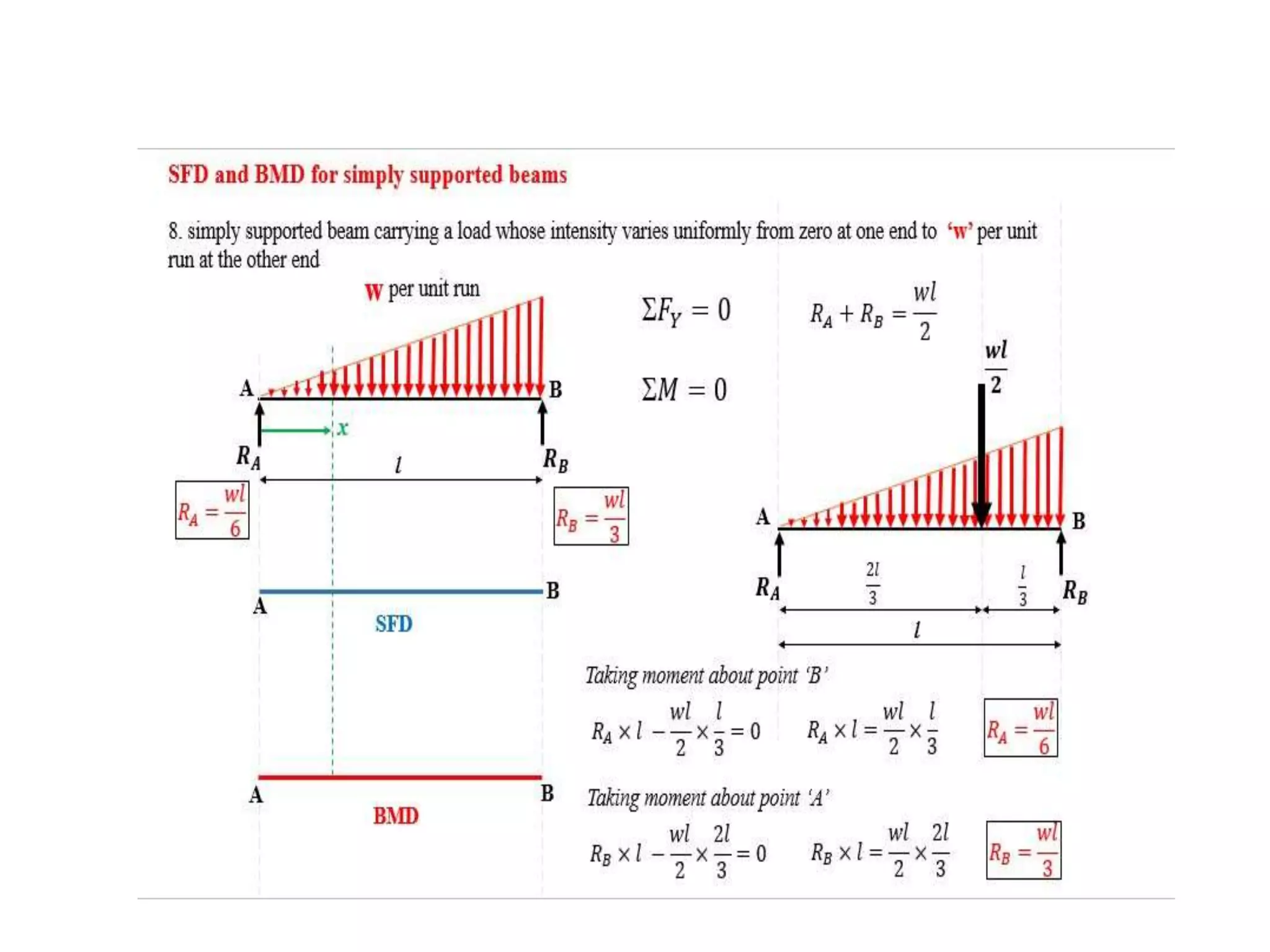
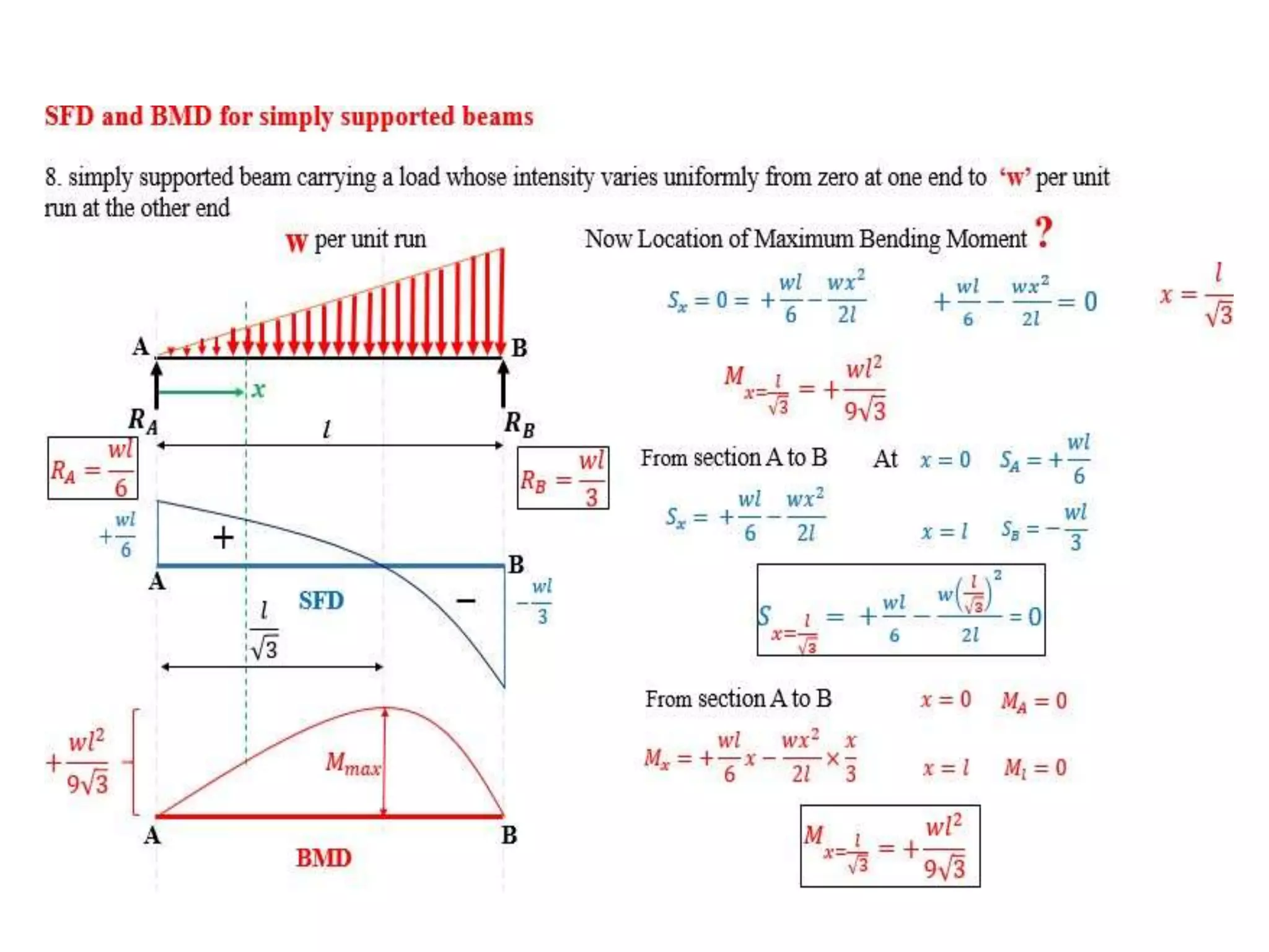
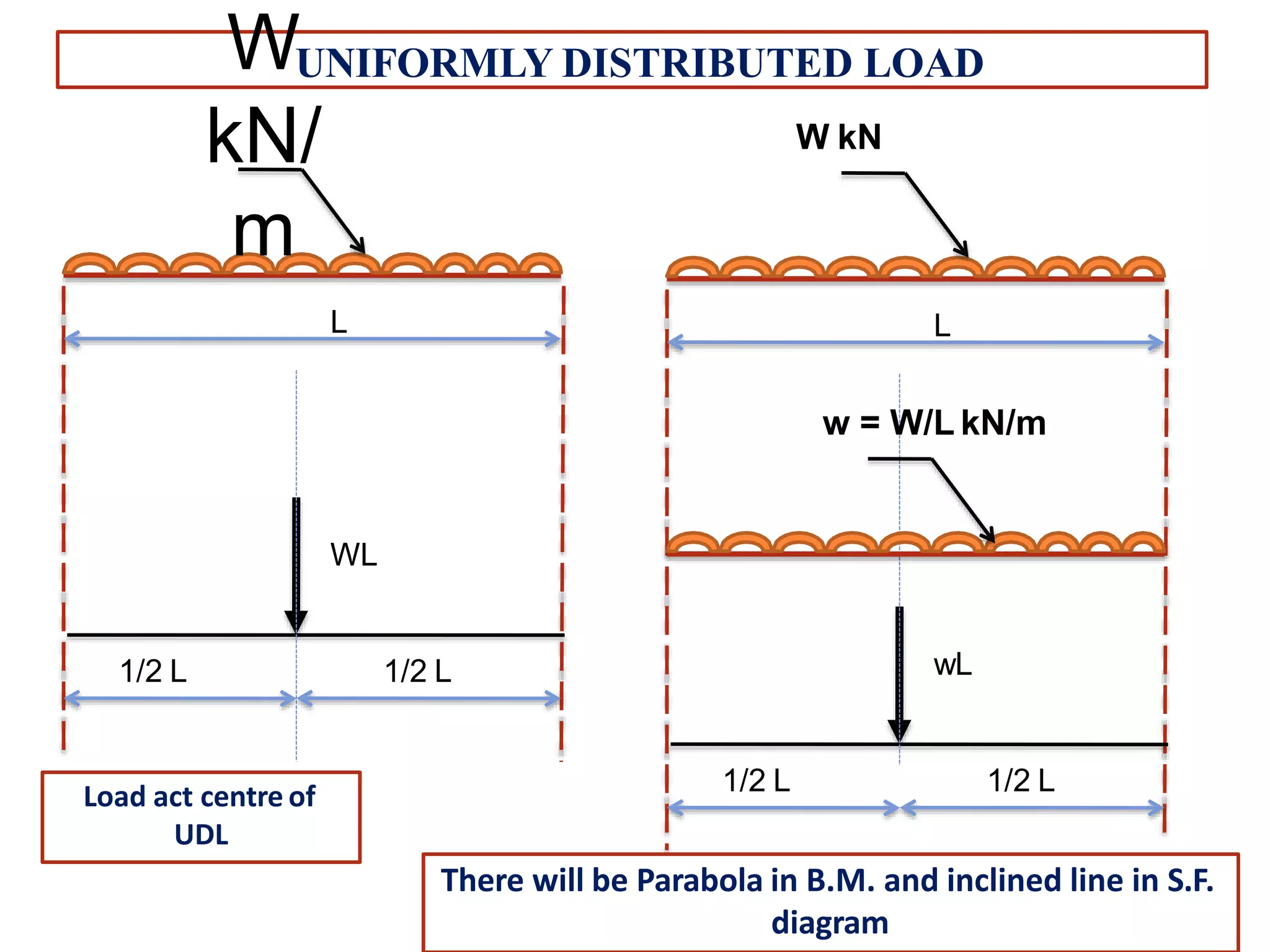
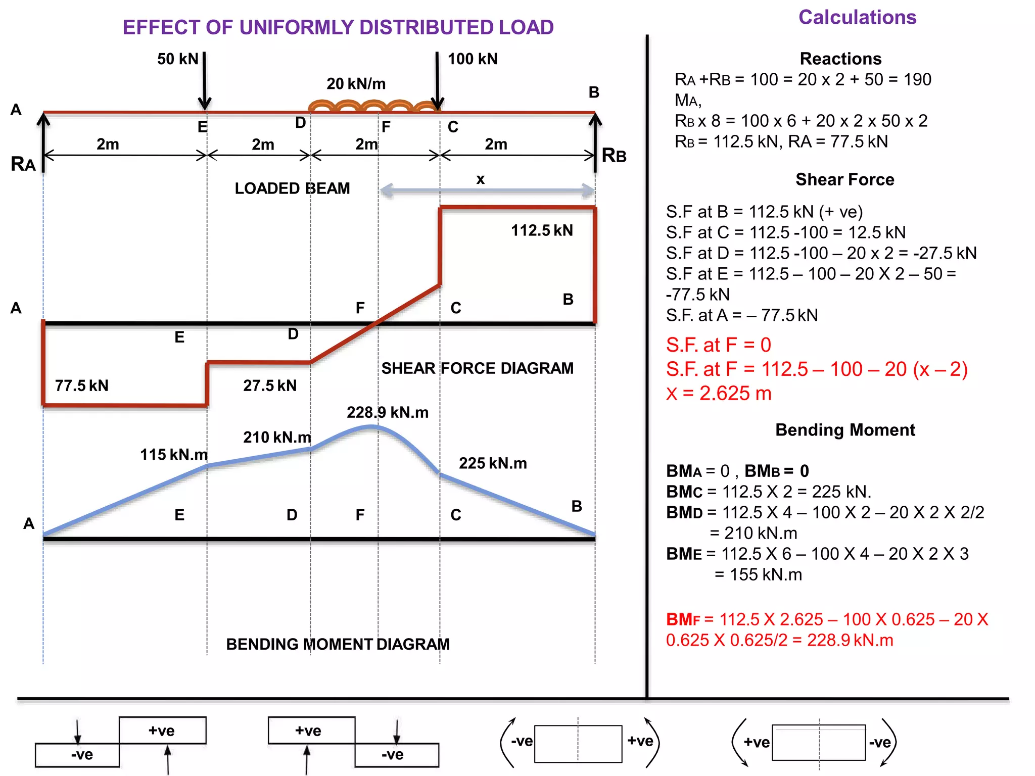
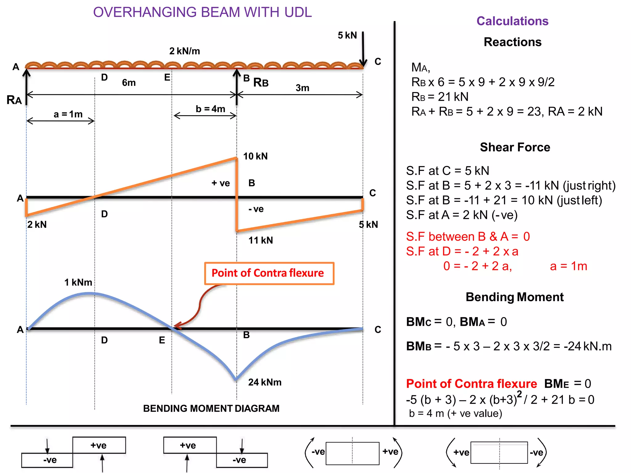
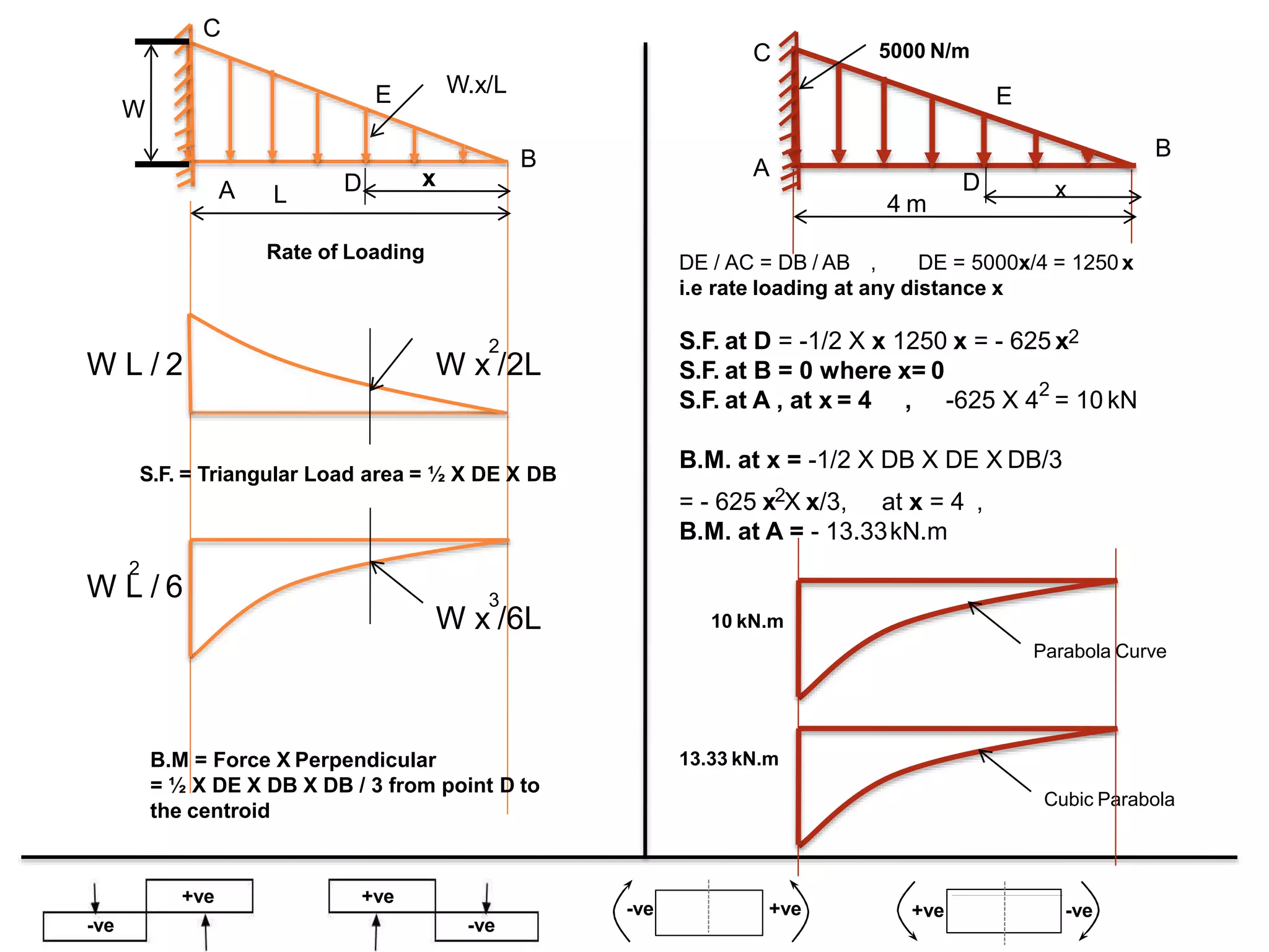
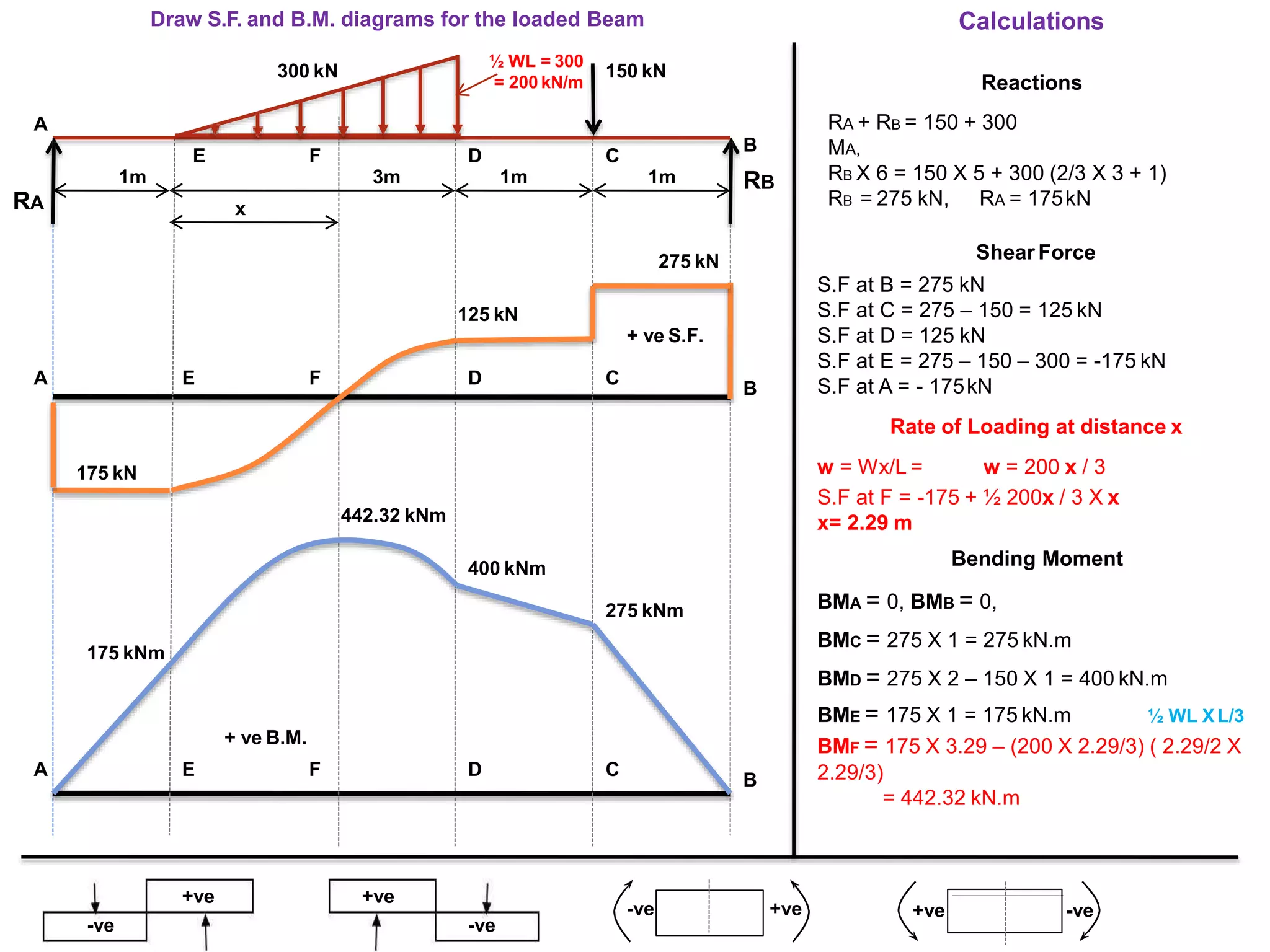
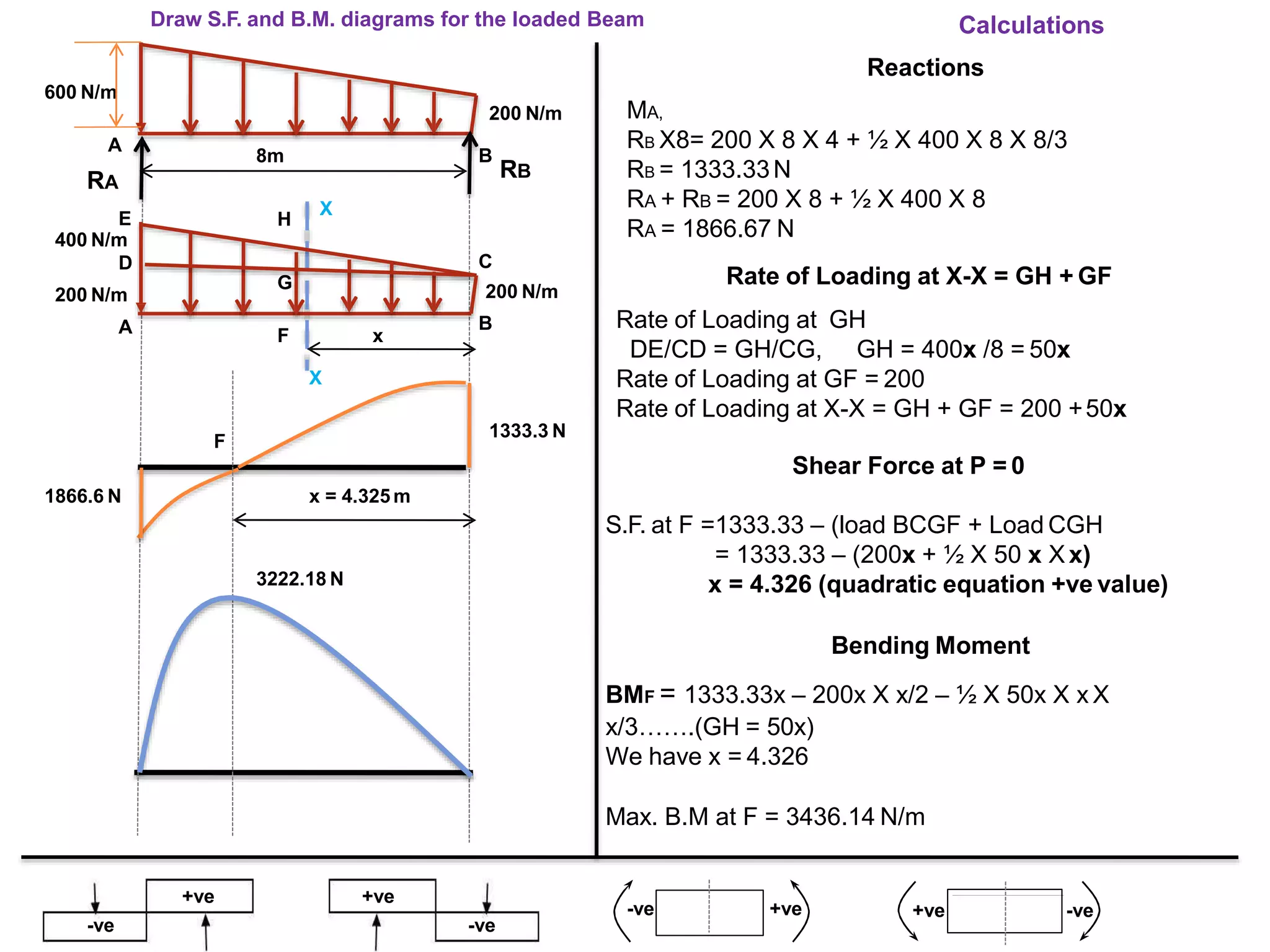
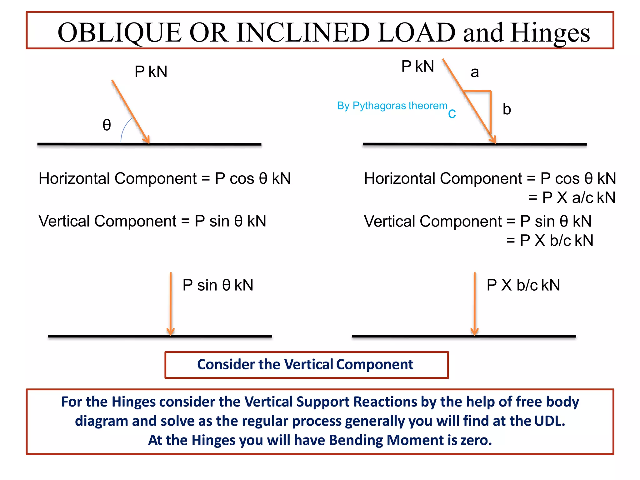
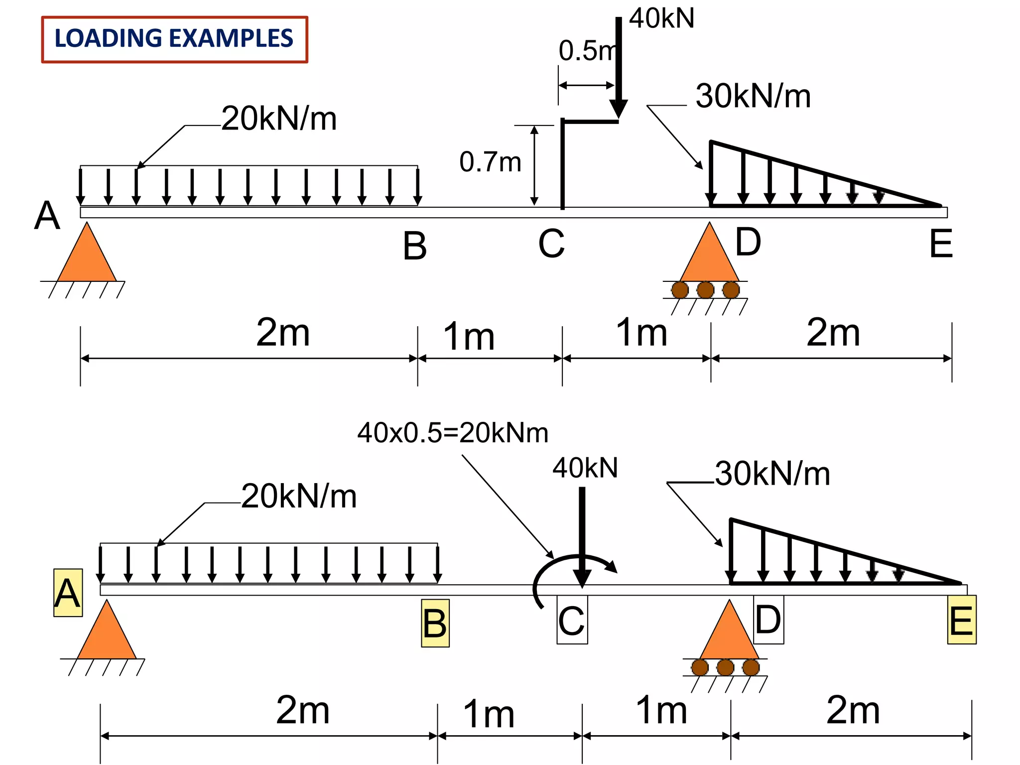
By:-
Ashish Mishra
SHEAR FORCE AND BENDING MOMENT
Beam: It is a structural member which is subjected to transverse
load.
Transverse load: The load which is perpendicular or it has non
zero component perpendicular to longitudinal axis of beam.
Shear force: it is the unbalanced force on either side of a section
parallel to cross section.
Moment: It is the product of force and perpendicular distance
between line of action of the force and the point about which
moment is required to be calculated.
Bending moment: It is the unbalanced moment on either side of
section, in the plane of beam.
TYPES OF LOAD
Sr. No. Type of load Example Description
1. Point Load Concentrated Load acts at a point.
2.
Uniformly Distributed
Load
UDL:- uniform load distribution
over wide area. Rate of loading per
unit length.
3.
Uniformly Varying
Load (Triangular
Distributed Load)
UVL:- Intensity of load at one point
to that at the other, eg. w1/m at C
to w2/m at D
4. Couple
A beam may be subjected to a
couple.
5. Oblique Load
The effect of Horizontal
components is to cause a thrust in
the beam. Vertical components of
the load cause bending and shear
& are treated as usual vertical
loads on a beam
TYPES OF SUPPORTS
Sr. No. Type of support Example Description
1.
Knife
Edge
Support
Contact Area Insignificant.
Provides only vertical reaction
No resistance to turning or
lateral displacement
2.
Roller
Support
(Horizontal
Plane)
Rollers on Horizontal Plane
Support reaction is vertical.
No resistance to turning or lateral
displacement
3.
Roller Support
(Inclined
Plane)
Rollers on Inclined Plane
Support reaction is perpendicular
to inclined plane.
Allow turning or
lateral displacement.
4.
Hinged/Pi
n Support
Allows turning but doesn’t allow any
lateral movement.
Support reaction could be in
any direction.
Can be determined by resolving applied
in horizontal. & Vertical. direction
5. Fixed Support
Doesn’t allow rotation or
translation.
TYPES OF BEAMS
Sr. No. Type of Beam Example Description
1. Cantilever Beam
Beams have one end rigidly
built into the support.
Large span or heavy loads
provided by additional support
are known as propel and beam
as a propped cantilever.
2.
Simply Supported
Beam
Beams with knife edge
supports or roller supports at
ends.
3.
Beams with
Overhangs
Portion of a beam that goes
beyond the support is called
overhanging, may be on one or
both ends.
4. Fixed Beams
Rigidly built-in-supports at
both ends. Beam have support
reaction and a fixing moments
at each end.
5. Continuous Beams
Beams that cover more than
one span.
Both shear force and bending moment are vector quantities
requiring a convention of signs in order that values of opposite sense
may be separated. Mathematical signs are chosen since it is in
calculation problems that it becomes necessary to use such a
convention
TABEL 1. Sign convention and units for shearing force and bending moment
LOAD
EFFECT
SYMBOL
SIGN CONVENTION
UNITS
POSITIVE
(+)
NEGATIVE (-)
Shear
force
Q, V,S N
KN
Bending
moment
M
(bottom fibers in tension) (top fibers in tension)
N·mm
kN·m
BEAMS IN BENDING
BEAMS IN BENDING
The shearing force, at any transverse section in a loaded beam, is the
algebraic sum of all the forces acting on one (either) side of the
section.
The bending moment, at any transverse section in a loaded beam, is
the algebraic sum of the moments about the sections of all the forces
acting on one (either) side of the section.
RA RB
A
V1 V2 V3 V4
x
B
a4a3
a2
a1
a b
Working to the left of x:
Qx  RA  V1 V2  V3
Mx  RA a  V1 a1  V2 a2  V3 a3
Working to the right of x:
Qx  RB V4
Mx  RB b  V4 a4
THINGS TO REMEMBER FOR DRAWING OF S.F & B.M
 Start from right hand section.
 Use Sign convention of the side which you are choosing i.e Right or Left.
 If the thing are complicated use other side of section.
 Start from zero and end to zero. B.M at the ends will be zero.
 End point of S.F. will be equal and opposite to the reaction at that point.
 Mark the points and draw the diagram considering the type of load.
 At change in nature of forces there will be two points in shear force
diagram.
 At Couple there will be two points in B.M Diagram.
•Beams are assumed to be always straight, horizontal & of uniform c/s &
structure, unless otherwise specified.
•Self weight of Beam neglected unless its definite value is given.
S.F may be max. at supports or under point loads or where S.F. is zero where
B.M. may be maximum at point where S.F. is zero or where S.F. changes its
nature.
Variation of Shear force and bending moments
Type of load
SFD/BMD
Between Point
Load OR No load
region
Between UDL
region
Between UVL
region
Shear Force
Diagram
Horizontal line Inclined line Two-degree curve
(Parabola)
Bending Moment
Diagram
Inclined line Two-degree curve
(Parabola)
Three-degree curve
(Cubic-Parabola)
Variation of Shear force and bending moments for various
standard loads are as shown in the following Table
Table: Variation of Shear force and bending moments
a
X
X
SHEAR FORCE DIAGRAM
BENDING MOMENT DIAGRAM
35
20
20
35
35
35
20
20
C
D
E
B
A
F
20
25.5
20
Draw S.F. and B.M. diagrams for the loaded Beam Point Load
20 kN
C D E
20 kN
B
1m 1.3m 1.3m 1m
LOADED BEAM
A
70 kN
RC RE
Shear Force
S.F at B = -20kN
S.F at E = 55 - 20 = 35 kN
S.F at D = -20 – 70 + 55 = -35kN
S.F at C = -20 + 55 - 70 + 55 = 20kN
Symmetrical loading
Rc = RE = 20 + 70 + 20 = 55kN
2
Calculations
Bending Moment
BME = -20 X 1 = -20 kNm.
BMD = -20 X 2.3 + 55 X 1.3 = 25.5kNm.
BMC = -20(1.3 + 1.3 +1) + 55(1.3 + 1.3)
-70 X 1.3 = -20 kNm.
BMX = - 20 (a + 1) + 55a = 35 a –20
Point of Contra flexure BMX = 0
a = 0.57
+ve
-ve
+ve
-ve
+ve-ve -ve+ve
Point of Contra flexure
It is the point on the bending moment diagram where bending moment
changes the sign from positive to negative or vice versa.
It is also called ‘Inflection point’. At the point of inflection point or contra
flexure the bending moment is zero.
Point of Contra flexure OR Inflection point
UNIFORMLY DISTRIBUTED LOAD
WL
1/2 L
L
1/2 L
Load act centre of
UDL
W
kN/
m
wL
1/2 L
L
1/2 L
W kN
w = W/L kN/m
There will be Parabola in B.M. and inclined line in S.F.
diagram
2m 2m
BENDING MOMENT DIAGRAM
A
Reactions
RA +RB = 100 = 20 x 2 + 50 = 190
MA,
RB x 8 = 100 x 6 + 20 x 2 x 50 x 2
RB = 112.5 kN, RA = 77.5 kN
RB
Calculations
BMA = 0 , BMB = 0
BMC = 112.5 X 2 = 225 kN.
BMD = 112.5 X 4 – 100 X 2 – 20 X 2 X 2/2
= 210 kN.m
BME = 112.5 X 6 – 100 X 4 – 20 X 2 X 3
= 155 kN.m
BMF = 112.5 X 2.625 – 100 X 0.625 – 20 X
0.625 X 0.625/2 = 228.9 kN.m
+ve
-ve
+ve
-ve
+ve-ve -ve+ve
20 kN/m
EFFECT OF UNIFORMLY DISTRIBUTED LOAD
50 kN 100 kN
E D
2m
LOADED BEAM
F C
B
RA
2m
Shear Force
S.F at B = 112.5 kN (+ ve)
S.F at C = 112.5 -100 = 12.5 kN
S.F at D = 112.5 -100 – 20 x 2 = -27.5 kN
S.F at E = 112.5 – 100 – 20 X 2 – 50 =
-77.5 kN
S.F. at A = – 77.5kN
S.F. at F = 0
S.F. at F = 112.5 – 100 – 20 (x – 2)
X = 2.625 m
Bending Moment
A
E D
F C
B
E D F C
B
A
x
112.5 kN
27.5 kN77.5 kN
225 kN.m
SHEAR FORCE DIAGRAM
228.9 kN.m
210 kN.m
115 kN.m
BENDING MOMENT DIAGRAM
EFFECT OF COUPLE
Reactions
RA + RB = 20 X 4 = 80
MA,
RB X 10 = 40 + 20 X 4 X 2
RB = 20 kN, RA = 60 kN
RB
Calculations
Bending Moment
BMA = 0, BMB = 0,
BMC = 20 x 5 = 100 kN.m (just before)
BMC = 100 – 40 = 60 (just after)
BMD = 20 x 6 – 40 = 80 kN.m
BME = 20 x 7 – 40 – 20 x 1 x 0.5
= 90 kN.m
+ve
-ve
+ve
-ve
+ve-ve -ve+ve
RA
40 kN-m
4m 5m
A
20 kN/m
E D C
B
1m
X = 7m
D C
SHEAR FORCE DIAGRAM
B
A + ve S.F.
- ve
E
D C B
A
20 kN
60 kN
90 kN.m
80 kN.m
100 kN.m
60 kN.m
+ ve BM
Shear Force
S.F at B = 20 kN
S.F at C = 20 kN
S.F at A = -60kN
S.F at E = 0
S.F at E = 20 – 20 (x-6)
x = 7m
E
a = 1m
BENDING MOMENT DIAGRAM
OVERHANGING BEAM WITH UDL
MA,
RB x 6 = 5 x 9 + 2 x 9 x 9/2
RB = 21 kN
RA + RB = 5 + 2 x 9 = 23, RA = 2 kN
Calculations
Reactions
+ve
-ve
+ve
-ve
+ve-ve -ve+ve
RA
ED
3m
A
2 kN/m
B
RB
C
6m
5 kN
A
D
C
11 kN
5 kN
10 kN
+ ve B
- ve
2 kN
Point of Contra flexure
1 kNm
A
D E
B
C
24 kNm
Shear Force
S.F at C = 5 kN
S.F at B = 5 + 2 x 3 = -11 kN (justright)
S.F at B = -11 + 21 = 10 kN (justleft)
S.F at A = 2 kN (-ve)
S.F between B & A = 0
S.F at D = - 2 + 2 x a
0 = - 2 + 2 a, a = 1m
Bending Moment
BMC = 0, BMA = 0
BMB = - 5 x 3 – 2 x 3 x 3/2 = -24kN.m
b = 4m
Point of Contra flexure BME = 0
-5 (b + 3) – 2 x (b+3)
2
/ 2 + 21 b = 0
b = 4 m (+ ve value)
BENDING MOMENT DIAGRAM
CANTILEVER WITH UDL
Shear Force
S.F at B = 10 kN
S.F at C = 10 + 5 x 2 = -20kN
S.F at D = 10 + 5 x 2 + 20 = - 40kN
S.F atA = 10 + 5 x 2 + 20 + 40 x 3
= - 160 kN
Calculations
Bending Moment
BMB = 0
BMC = 10 x 2 + 5 x 2 x 2/2 = -30 kNm.
BMD = 10 x 3 + 5 x 2 x (2/2 +1)
= 50 kN.m
BME = 10 x 5 + 5 x 2 x ( 2/2 + 3) +20
x 2
= - 130 k Nm
BMA = 10 x 8 + 5 x 2 x (2/2 + 6) + 20x
5 + 40 x 3 x 3/2
= - 430 kN.m.
+ve
-ve
+ve
-ve
+ve-ve -ve+ve
20 kN
3m 2m
A
40 kN/m
E D C
B
2m
10 kN
5 kN/m
1m
- VE S.F.
A
E
D
C
B
20 kN
10 kN
40 kN
160 kN
430 kN.m
130 kN.m
50 kN.m
Parabolic curve
30 kN.m- VE B.M.
Parabolic curve
A E D C B
UNIFORMLY VARYING LOAD
W N/m
W N/m
1/3 L
L
2/3 L
Load Act the centroid of the
Triangular Area
There will be Parabola in both S.F. and B.M
+ve
-ve
+ve
-ve
+ve-ve -ve+ve
C
A
W
L D
E
x
W.x/L
B
5000 N/mC
A
4 m
D
E
x
B
Rate of Loading
S.F. = Triangular Load area = ½ X DE X DB
W x /2L
2
W L / 2
W x /6L
3W L / 6
2
B.M = Force X Perpendicular
= ½ X DE X DB X DB / 3 from point D to
the centroid
Cubic Parabola
13.33 kN.m
Parabola Curve
10 kN.m
DE / AC = DB / AB , DE = 5000x/4 = 1250 x
i.e rate loading at any distance x
= - 625 x2X x/3, at x = 4 ,
B.M. at A = - 13.33kN.m
S.F. at D = -1/2 X x 1250 x = - 625 x2
S.F. at B = 0 where x= 0
S.F. at A , at x = 4 , -625 X 4
2
= 10 kN
B.M. at x = -1/2 X DB X DE X DB/3
Draw S.F. and B.M. diagrams for the loaded Beam
Reactions
RA + RB = 150 + 300
MA,
RB X 6 = 150 X 5 + 300 (2/3 X 3 + 1)
RB = 275 kN, RA = 175kN
Shear Force
S.F at B = 275 kN
S.F at C = 275 – 150 = 125 kN
S.F at D = 125 kN
S.F at E = 275 – 150 – 300 = -175 kN
S.F at A = - 175kN
Calculations
+ve
-ve
+ve
-ve
+ve-ve -ve+ve
RA
300 kN
1m 1m
A
E D C
B
RB3m
150 kN
1m
F
½ WL = 300
= 200 kN/m
x
A E F D C
B
275 kN
125 kN
175 kN
+ ve S.F.
+ ve B.M.
175 kNm
442.32 kNm
400 kNm
275 kNm
A E F D C
B
Rate of Loading at distance x
w = Wx/L = w = 200 x / 3
S.F at F = -175 + ½ 200x / 3 X x
x= 2.29 m
Bending Moment
BMA = 0, BMB = 0,
BMC = 275 X 1 = 275 kN.m
BMD = 275 X 2 – 150 X 1 = 400 kN.m
BME = 175 X 1 = 175 kN.m
BMF = 175 X 3.29 – (200 X 2.29/3) ( 2.29/2 X
2.29/3)
= 442.32 kN.m
½ WL X L/3
Draw S.F. and B.M. diagrams for the loaded Beam
MA,
RB X8= 200 X 8 X 4 + ½ X 400 X 8 X 8/3
RB = 1333.33N
RA + RB = 200 X 8 + ½ X 400 X 8
RA = 1866.67 N
Rate of Loading at X-X = GH + GF
Rate of Loading at GH
DE/CD = GH/CG, GH = 400x /8 = 50x
Rate of Loading at GF = 200
Rate of Loading at X-X = GH + GF = 200 +50x
Calculations
Reactions
+ve
-ve
+ve
-ve
+ve-ve -ve+ve
Bending Moment
BMF = 1333.33x – 200x X x/2 – ½ X 50x X x X
x/3…….(GH = 50x)
We have x = 4.326
Max. B.M at F = 3436.14 N/m
200 N/m
600 N/m
8m B
RB
1333.3 N
1866.6 N x = 4.325 m
3222.18 N
H
G
F x
C
200 N/m
B
A
RA
E
400 N/m
D
200 N/m
A
X
X
Shear Force at P = 0
S.F. at F =1333.33 – (load BCGF + Load CGH
= 1333.33 – (200x + ½ X 50 x X x)
x = 4.326 (quadratic equation +ve value)
F
OBLIQUE OR INCLINED LOAD and Hinges
Consider the Vertical Component
θ
P kN
Horizontal Component = P cos θ kN
Vertical Component = P sin θ kN
P sin θ kN
a
b
P kN
Horizontal Component = P cos θ kN
= P X a/c kN
Vertical Component = P sin θ kN
= P X b/c kN
By Pythagoras theorem
c
P X b/c kN
For the Hinges consider the Vertical Support Reactions by the help of free body
diagram and solve as the regular process generally you will find at theUDL.
At the Hinges you will have Bending Moment is zero.
20kN/m
30kN/m
2m 2m
A
D
1m 1m
0.7m
B C E
LOADING EXAMPLES
40x0.5=20kNm
20kN/m
40kN 30kN/m
2m 2m
A
D
1m 1m
B C E
40kN
0.5m
Thank You

Shear Force and Bending moment Diagram

  • 1.
  • 2.
    SHEAR FORCE ANDBENDING MOMENT Beam: It is a structural member which is subjected to transverse load. Transverse load: The load which is perpendicular or it has non zero component perpendicular to longitudinal axis of beam. Shear force: it is the unbalanced force on either side of a section parallel to cross section. Moment: It is the product of force and perpendicular distance between line of action of the force and the point about which moment is required to be calculated. Bending moment: It is the unbalanced moment on either side of section, in the plane of beam.
  • 3.
    TYPES OF LOAD Sr.No. Type of load Example Description 1. Point Load Concentrated Load acts at a point. 2. Uniformly Distributed Load UDL:- uniform load distribution over wide area. Rate of loading per unit length. 3. Uniformly Varying Load (Triangular Distributed Load) UVL:- Intensity of load at one point to that at the other, eg. w1/m at C to w2/m at D 4. Couple A beam may be subjected to a couple. 5. Oblique Load The effect of Horizontal components is to cause a thrust in the beam. Vertical components of the load cause bending and shear & are treated as usual vertical loads on a beam
  • 4.
    TYPES OF SUPPORTS Sr.No. Type of support Example Description 1. Knife Edge Support Contact Area Insignificant. Provides only vertical reaction No resistance to turning or lateral displacement 2. Roller Support (Horizontal Plane) Rollers on Horizontal Plane Support reaction is vertical. No resistance to turning or lateral displacement 3. Roller Support (Inclined Plane) Rollers on Inclined Plane Support reaction is perpendicular to inclined plane. Allow turning or lateral displacement. 4. Hinged/Pi n Support Allows turning but doesn’t allow any lateral movement. Support reaction could be in any direction. Can be determined by resolving applied in horizontal. & Vertical. direction 5. Fixed Support Doesn’t allow rotation or translation.
  • 5.
    TYPES OF BEAMS Sr.No. Type of Beam Example Description 1. Cantilever Beam Beams have one end rigidly built into the support. Large span or heavy loads provided by additional support are known as propel and beam as a propped cantilever. 2. Simply Supported Beam Beams with knife edge supports or roller supports at ends. 3. Beams with Overhangs Portion of a beam that goes beyond the support is called overhanging, may be on one or both ends. 4. Fixed Beams Rigidly built-in-supports at both ends. Beam have support reaction and a fixing moments at each end. 5. Continuous Beams Beams that cover more than one span.
  • 6.
    Both shear forceand bending moment are vector quantities requiring a convention of signs in order that values of opposite sense may be separated. Mathematical signs are chosen since it is in calculation problems that it becomes necessary to use such a convention TABEL 1. Sign convention and units for shearing force and bending moment LOAD EFFECT SYMBOL SIGN CONVENTION UNITS POSITIVE (+) NEGATIVE (-) Shear force Q, V,S N KN Bending moment M (bottom fibers in tension) (top fibers in tension) N·mm kN·m BEAMS IN BENDING
  • 9.
    BEAMS IN BENDING Theshearing force, at any transverse section in a loaded beam, is the algebraic sum of all the forces acting on one (either) side of the section. The bending moment, at any transverse section in a loaded beam, is the algebraic sum of the moments about the sections of all the forces acting on one (either) side of the section. RA RB A V1 V2 V3 V4 x B a4a3 a2 a1 a b Working to the left of x: Qx  RA  V1 V2  V3 Mx  RA a  V1 a1  V2 a2  V3 a3 Working to the right of x: Qx  RB V4 Mx  RB b  V4 a4
  • 10.
    THINGS TO REMEMBERFOR DRAWING OF S.F & B.M  Start from right hand section.  Use Sign convention of the side which you are choosing i.e Right or Left.  If the thing are complicated use other side of section.  Start from zero and end to zero. B.M at the ends will be zero.  End point of S.F. will be equal and opposite to the reaction at that point.  Mark the points and draw the diagram considering the type of load.  At change in nature of forces there will be two points in shear force diagram.  At Couple there will be two points in B.M Diagram. •Beams are assumed to be always straight, horizontal & of uniform c/s & structure, unless otherwise specified. •Self weight of Beam neglected unless its definite value is given. S.F may be max. at supports or under point loads or where S.F. is zero where B.M. may be maximum at point where S.F. is zero or where S.F. changes its nature.
  • 11.
    Variation of Shearforce and bending moments Type of load SFD/BMD Between Point Load OR No load region Between UDL region Between UVL region Shear Force Diagram Horizontal line Inclined line Two-degree curve (Parabola) Bending Moment Diagram Inclined line Two-degree curve (Parabola) Three-degree curve (Cubic-Parabola) Variation of Shear force and bending moments for various standard loads are as shown in the following Table Table: Variation of Shear force and bending moments
  • 37.
    a X X SHEAR FORCE DIAGRAM BENDINGMOMENT DIAGRAM 35 20 20 35 35 35 20 20 C D E B A F 20 25.5 20 Draw S.F. and B.M. diagrams for the loaded Beam Point Load 20 kN C D E 20 kN B 1m 1.3m 1.3m 1m LOADED BEAM A 70 kN RC RE Shear Force S.F at B = -20kN S.F at E = 55 - 20 = 35 kN S.F at D = -20 – 70 + 55 = -35kN S.F at C = -20 + 55 - 70 + 55 = 20kN Symmetrical loading Rc = RE = 20 + 70 + 20 = 55kN 2 Calculations Bending Moment BME = -20 X 1 = -20 kNm. BMD = -20 X 2.3 + 55 X 1.3 = 25.5kNm. BMC = -20(1.3 + 1.3 +1) + 55(1.3 + 1.3) -70 X 1.3 = -20 kNm. BMX = - 20 (a + 1) + 55a = 35 a –20 Point of Contra flexure BMX = 0 a = 0.57 +ve -ve +ve -ve +ve-ve -ve+ve Point of Contra flexure
  • 38.
    It is thepoint on the bending moment diagram where bending moment changes the sign from positive to negative or vice versa. It is also called ‘Inflection point’. At the point of inflection point or contra flexure the bending moment is zero. Point of Contra flexure OR Inflection point
  • 39.
    UNIFORMLY DISTRIBUTED LOAD WL 1/2L L 1/2 L Load act centre of UDL W kN/ m wL 1/2 L L 1/2 L W kN w = W/L kN/m There will be Parabola in B.M. and inclined line in S.F. diagram
  • 40.
    2m 2m BENDING MOMENTDIAGRAM A Reactions RA +RB = 100 = 20 x 2 + 50 = 190 MA, RB x 8 = 100 x 6 + 20 x 2 x 50 x 2 RB = 112.5 kN, RA = 77.5 kN RB Calculations BMA = 0 , BMB = 0 BMC = 112.5 X 2 = 225 kN. BMD = 112.5 X 4 – 100 X 2 – 20 X 2 X 2/2 = 210 kN.m BME = 112.5 X 6 – 100 X 4 – 20 X 2 X 3 = 155 kN.m BMF = 112.5 X 2.625 – 100 X 0.625 – 20 X 0.625 X 0.625/2 = 228.9 kN.m +ve -ve +ve -ve +ve-ve -ve+ve 20 kN/m EFFECT OF UNIFORMLY DISTRIBUTED LOAD 50 kN 100 kN E D 2m LOADED BEAM F C B RA 2m Shear Force S.F at B = 112.5 kN (+ ve) S.F at C = 112.5 -100 = 12.5 kN S.F at D = 112.5 -100 – 20 x 2 = -27.5 kN S.F at E = 112.5 – 100 – 20 X 2 – 50 = -77.5 kN S.F. at A = – 77.5kN S.F. at F = 0 S.F. at F = 112.5 – 100 – 20 (x – 2) X = 2.625 m Bending Moment A E D F C B E D F C B A x 112.5 kN 27.5 kN77.5 kN 225 kN.m SHEAR FORCE DIAGRAM 228.9 kN.m 210 kN.m 115 kN.m
  • 41.
    BENDING MOMENT DIAGRAM EFFECTOF COUPLE Reactions RA + RB = 20 X 4 = 80 MA, RB X 10 = 40 + 20 X 4 X 2 RB = 20 kN, RA = 60 kN RB Calculations Bending Moment BMA = 0, BMB = 0, BMC = 20 x 5 = 100 kN.m (just before) BMC = 100 – 40 = 60 (just after) BMD = 20 x 6 – 40 = 80 kN.m BME = 20 x 7 – 40 – 20 x 1 x 0.5 = 90 kN.m +ve -ve +ve -ve +ve-ve -ve+ve RA 40 kN-m 4m 5m A 20 kN/m E D C B 1m X = 7m D C SHEAR FORCE DIAGRAM B A + ve S.F. - ve E D C B A 20 kN 60 kN 90 kN.m 80 kN.m 100 kN.m 60 kN.m + ve BM Shear Force S.F at B = 20 kN S.F at C = 20 kN S.F at A = -60kN S.F at E = 0 S.F at E = 20 – 20 (x-6) x = 7m E
  • 42.
    a = 1m BENDINGMOMENT DIAGRAM OVERHANGING BEAM WITH UDL MA, RB x 6 = 5 x 9 + 2 x 9 x 9/2 RB = 21 kN RA + RB = 5 + 2 x 9 = 23, RA = 2 kN Calculations Reactions +ve -ve +ve -ve +ve-ve -ve+ve RA ED 3m A 2 kN/m B RB C 6m 5 kN A D C 11 kN 5 kN 10 kN + ve B - ve 2 kN Point of Contra flexure 1 kNm A D E B C 24 kNm Shear Force S.F at C = 5 kN S.F at B = 5 + 2 x 3 = -11 kN (justright) S.F at B = -11 + 21 = 10 kN (justleft) S.F at A = 2 kN (-ve) S.F between B & A = 0 S.F at D = - 2 + 2 x a 0 = - 2 + 2 a, a = 1m Bending Moment BMC = 0, BMA = 0 BMB = - 5 x 3 – 2 x 3 x 3/2 = -24kN.m b = 4m Point of Contra flexure BME = 0 -5 (b + 3) – 2 x (b+3) 2 / 2 + 21 b = 0 b = 4 m (+ ve value)
  • 43.
    BENDING MOMENT DIAGRAM CANTILEVERWITH UDL Shear Force S.F at B = 10 kN S.F at C = 10 + 5 x 2 = -20kN S.F at D = 10 + 5 x 2 + 20 = - 40kN S.F atA = 10 + 5 x 2 + 20 + 40 x 3 = - 160 kN Calculations Bending Moment BMB = 0 BMC = 10 x 2 + 5 x 2 x 2/2 = -30 kNm. BMD = 10 x 3 + 5 x 2 x (2/2 +1) = 50 kN.m BME = 10 x 5 + 5 x 2 x ( 2/2 + 3) +20 x 2 = - 130 k Nm BMA = 10 x 8 + 5 x 2 x (2/2 + 6) + 20x 5 + 40 x 3 x 3/2 = - 430 kN.m. +ve -ve +ve -ve +ve-ve -ve+ve 20 kN 3m 2m A 40 kN/m E D C B 2m 10 kN 5 kN/m 1m - VE S.F. A E D C B 20 kN 10 kN 40 kN 160 kN 430 kN.m 130 kN.m 50 kN.m Parabolic curve 30 kN.m- VE B.M. Parabolic curve A E D C B
  • 44.
    UNIFORMLY VARYING LOAD WN/m W N/m 1/3 L L 2/3 L Load Act the centroid of the Triangular Area There will be Parabola in both S.F. and B.M
  • 45.
    +ve -ve +ve -ve +ve-ve -ve+ve C A W L D E x W.x/L B 5000N/mC A 4 m D E x B Rate of Loading S.F. = Triangular Load area = ½ X DE X DB W x /2L 2 W L / 2 W x /6L 3W L / 6 2 B.M = Force X Perpendicular = ½ X DE X DB X DB / 3 from point D to the centroid Cubic Parabola 13.33 kN.m Parabola Curve 10 kN.m DE / AC = DB / AB , DE = 5000x/4 = 1250 x i.e rate loading at any distance x = - 625 x2X x/3, at x = 4 , B.M. at A = - 13.33kN.m S.F. at D = -1/2 X x 1250 x = - 625 x2 S.F. at B = 0 where x= 0 S.F. at A , at x = 4 , -625 X 4 2 = 10 kN B.M. at x = -1/2 X DB X DE X DB/3
  • 46.
    Draw S.F. andB.M. diagrams for the loaded Beam Reactions RA + RB = 150 + 300 MA, RB X 6 = 150 X 5 + 300 (2/3 X 3 + 1) RB = 275 kN, RA = 175kN Shear Force S.F at B = 275 kN S.F at C = 275 – 150 = 125 kN S.F at D = 125 kN S.F at E = 275 – 150 – 300 = -175 kN S.F at A = - 175kN Calculations +ve -ve +ve -ve +ve-ve -ve+ve RA 300 kN 1m 1m A E D C B RB3m 150 kN 1m F ½ WL = 300 = 200 kN/m x A E F D C B 275 kN 125 kN 175 kN + ve S.F. + ve B.M. 175 kNm 442.32 kNm 400 kNm 275 kNm A E F D C B Rate of Loading at distance x w = Wx/L = w = 200 x / 3 S.F at F = -175 + ½ 200x / 3 X x x= 2.29 m Bending Moment BMA = 0, BMB = 0, BMC = 275 X 1 = 275 kN.m BMD = 275 X 2 – 150 X 1 = 400 kN.m BME = 175 X 1 = 175 kN.m BMF = 175 X 3.29 – (200 X 2.29/3) ( 2.29/2 X 2.29/3) = 442.32 kN.m ½ WL X L/3
  • 47.
    Draw S.F. andB.M. diagrams for the loaded Beam MA, RB X8= 200 X 8 X 4 + ½ X 400 X 8 X 8/3 RB = 1333.33N RA + RB = 200 X 8 + ½ X 400 X 8 RA = 1866.67 N Rate of Loading at X-X = GH + GF Rate of Loading at GH DE/CD = GH/CG, GH = 400x /8 = 50x Rate of Loading at GF = 200 Rate of Loading at X-X = GH + GF = 200 +50x Calculations Reactions +ve -ve +ve -ve +ve-ve -ve+ve Bending Moment BMF = 1333.33x – 200x X x/2 – ½ X 50x X x X x/3…….(GH = 50x) We have x = 4.326 Max. B.M at F = 3436.14 N/m 200 N/m 600 N/m 8m B RB 1333.3 N 1866.6 N x = 4.325 m 3222.18 N H G F x C 200 N/m B A RA E 400 N/m D 200 N/m A X X Shear Force at P = 0 S.F. at F =1333.33 – (load BCGF + Load CGH = 1333.33 – (200x + ½ X 50 x X x) x = 4.326 (quadratic equation +ve value) F
  • 48.
    OBLIQUE OR INCLINEDLOAD and Hinges Consider the Vertical Component θ P kN Horizontal Component = P cos θ kN Vertical Component = P sin θ kN P sin θ kN a b P kN Horizontal Component = P cos θ kN = P X a/c kN Vertical Component = P sin θ kN = P X b/c kN By Pythagoras theorem c P X b/c kN For the Hinges consider the Vertical Support Reactions by the help of free body diagram and solve as the regular process generally you will find at theUDL. At the Hinges you will have Bending Moment is zero.
  • 49.
    20kN/m 30kN/m 2m 2m A D 1m 1m 0.7m BC E LOADING EXAMPLES 40x0.5=20kNm 20kN/m 40kN 30kN/m 2m 2m A D 1m 1m B C E 40kN 0.5m
  • 50.