MODULE 2 ( PPT-2/4)
ROBOTICS AND
AUTOMATION
21ECE1673
SYLLABUS
MODULE-2
1 Actuators and Grippers : Electric Actuators T1 : 3.1
2 Hydraulic Actuators T1 : 3.2
3 Pneumatic Actuators T1 : 3.3
4 Selection of Motors T1 : 3.4
5 Grippers T1 : 3.5
ELECTRIC ACTUATORS
ELECTRIC ACTUATORS
Electric actuators
are generally those where an
electric motor drives robot links
through some mechanical transmission, e.g., gears, etc.
ELECTRIC ACTUATORS
In the early years of industrial robotics,
hydraulic robots were the most common,
but recent improvements in electric motor design
have meant that most new robots are of all-electric construction.
.
INDUSTRIAL ROBOT
ABB pioneered the world’s
first commercial all-
electric microprocessor-
controlled robot in 1974.
Since then, it has
introduced a number of
robotics innovations from
high-speed “delta” robots,
for picking and packaging,
to the world’s first truly
collaborative industrial
robot, YuMi, in 2015.
ELECTRIC ACTUATOR
COMPONENTS
ELECTRIC ACTUATOR - ADVANTAGES
1. Widespread availability of power supply.
2. Basic drive element electric motor is usually lighter than pressurized
fluid or compressed air.
3. High power-conversion efficiency.
4. No pollution of working environment.
5. Accuracy and repeatability of electric drive robots are normally better
than fluid power
6. Being relatively quiet and clean, they are very acceptable
environmentally.
7. They are easily maintained and repaired.
8. Structural components can be lightweight.
9. The drive system is well suited to electronic control.
ELECTRIC ACTUATOR -
DISADVANTAGES
1. Electrically driven robots often require the incorporation of some sort of mechanical
transmission system.
2. Additional power is required to move the additional masses of the transmission system.
3. Unwanted movements due to backlash and plays in the transmission elements.
4. Due to the increased complexity with the transmission system, we need complex control
requirement and additional cost for their procurement and maintenance.
5. Electric motors are not intrinsically safe, mainly, in explosive environments
WHAT’S BEING DONE ???
1. The above disadvantages are gradually being overcome with the introduction of direct-drive
motor system, in which the electric motor is a part of the relevant robot arm joint, thus,
eliminating the transmission elements.
2. Moreover, the introduction of newer brushless motors allow electric robots to be used in
some fi re-risk applications such as spray painting, as the possibility of sparking at the
motor brushes is eliminated.
3. Different types of electric motors are stepper motors, and the dc and ac motors
STEPPER MOTORS
DC MOTORS
AC MOTORS
DIFFERENT TYPES OF ELECTRIC
MOTORS
STEPPER MOTOR
STEPPER MOTORS
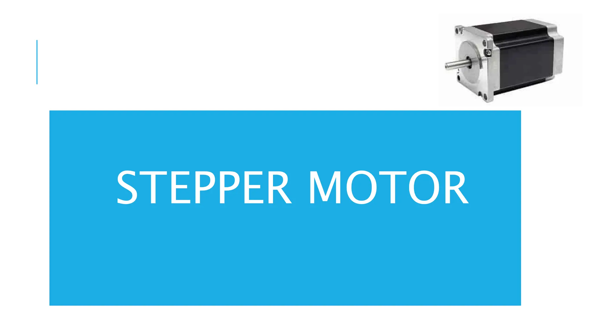
Stepper motor (Bipolar, 200 Steps/Rev, 20 X 30 mm, 3.9 V, 0.6 A/Phase)
[Courtesy: http://www.polulu.com]
STEPPER MOTOR
A stepper motor is an electric motor whose main feature is that its shaft rotates by
performing steps, that is, by moving by a fixed amount of degrees.
This feature is obtained thanks to the internal structure of the motor, and allows to
know the exact angular position of the shaft by simply counting how may steps
have been performed, with no need for a sensor.
APPLICATIONS
3D Printers: XY Table Drive, Media
Drive
Video Cameras: Pan, Tilt, Zoom,
Focus
Robots: Arms, End Effector
APPLICATIONS
Engraving Machines: XY Table Motion ATM Machines: Bill Movement, Tray Elevators
STEPPER MOTORS
Stepper motors (also called stepping motors or step motors) were first used for remote control
of the direction indicators of torpedo tubes and guns in British warships and later, for a similar
purpose, in the US Navy.
A variable reluctance-type stepper motor was first patented in 1919 by C.L. Walker, a Scottish
civil engineer.
However, its commercial production did not start until 1950.
STEPPER MOTORS
Used with small and medium robots and with teaching and hobby robots.
Used in industrial applications. (advantage: not requiring any feedback
system)
They are compatible with many feedback devices.
Used in full servo-control configurations in medium duty industrial robots.
STEPPER MOTORS
Because they are digitally controlled, they can be referred to as digital motors
or actuators.
These motors do not require the expense of digital- to-analog conversion
equipment when connected to a computer-control system
WORKING
WORKING
Normally, the shaft of a stepper motors rotates incrementally in equal
steps in response to a programmed input pulse train.
A current in any of the two phases, i.e., with P1 and P2, will magnetize
the pair into north and south poles, indicted with N and S, respectively.
Accordingly, the permanent magnet at the centre will rotate in order to
align itself along a particular phase, which is demonstrated.
Switching the currents in the two phases in an appropriate sequence can
produce either clockwise (CW) or counterclockwise (CCW) rotations.
WORKING
The switching sequence corresponds to what is known as half-stepping with a step
angle of 45o, whereas the full-stepping corresponds to 90o in which one phase is
energized at a time
WORKING
Micro-stepping (non-identical steps) up to 1/125 of full-step by changing the currents in small steps instead of
switching them on and off, as in the case of half- and full-stepping.
While micro-stepping is advantageous from the point of view of accurate motion control using a stepper motor, it
has the disadvantage of reduced motor torque.
The steps are achieved through phase activation or switching sequences triggered by the pulse sequences.
The switching logic that decides the states of the phases of a given step can be generated using a look-up table.
The same sequences can also be generated using a logic circuitry which is typically an electronic device.
WORKING
As the rotor indexes round a specific amount for each control pulse, any
error in positioning is noncumulative.
To know the final position of the rotor, all that is required is to count the
number of pulses fed into the stator’s phase winding of the motor.
The number of pulses per unit time determines the motor speed.
The rotor can be made to index slowly, coming to rest after each increment
or it can move rapidly in a continuous motion termed slewing. Maximum
dynamic torque in a stepper motor occurs at low pulse rates.
WORKING
Therefore, it can easily accelerate a load. Once the required position is achieved and the
command pulses cease, the shaft stops without the need for clutches or brakes.
The actual rotational movements or step angles of the shaft are obtainable typically from 1.8° to
90° depending on the particular motor choices.
Thus, with a nominal step angle of 1.8°, a stream of 1000 pulses will give an angular
displacement of 1800° or five complete revolutions.
They have also a low velocity capability without the need for gear reduction. For instance, if the
previously mentioned motor is driven by 500 pulses per second, it will rotate at 150 rpm.
Other advantages of the stepper motor are that the motor inertia is often low, and also if more
than one stepper motor is driven from the same source then they will maintain perfect
synchronizations.
STEPPER MOTOR ADVANTAGES
•Due to their internal structure, stepper motors do not require a sensor to detect the motor
position.
• Since the motor moves by performing “steps,” by simply counting these steps, you can
obtain the motor position at a given time.
•In addition, stepper motor control is pretty simple.
• The motor does need a driver, but does not need complex calculations or tuning to work
properly.
•Stepper motors offer good torque at low speeds, are great for holding position, and also tend
to have a long lifespan.
STEPPER MOTOR DISADVANTAGES
1. They can miss a step if the load torque is too high.
2. These motors always drain maximum current even when still, which makes efficiency worse and
can cause overheating.
3. Stepper motors have low torque and become pretty noisy at high speeds.
4. Finally, stepper motors have low power density and a low torque-to-inertia ratio.
5. Low efficiency
6. Drive inputs and circuitry have to be carefully designed in relation to the torque and speed
required.
TORQUE – SPEED
CHARACTERISTICS
TYPES OF STEPPER MOTORS
Types based on motor’s rotor:
1. Variable Reluctance
2. Permanent Magnet
3. Hybrid
VARIABLE-RELUCTANCE STEPPER MOTOR
Rotor rotates due to reluctance that is offers to magnetics flux lines. When
motor moves Reduction in reluctance in air,more energy in magnetic field.
WORKING
Magnetic reluctance, or reluctance, is the analog of electrical resistance. Just as current occurs only in a
closed loop, so magnetic flux occurs only around a closed path, although this path may be more varied
than that of the current.
The rotor is made of soft steel and it has four poles, whereas the stator has six poles. When one of the
phases, say AA’, is excited due to a dc current passing through the coils around the poles, the rotor
positions itself to complete the flux path.
Note that there is a main flux path through the aligned rotor and stator teeth, with secondary flux paths
occurring as indicated.
When rotor and stator teeth are aligned in this manner, the reluctance is minimized and the rotor is at rest
in this position. This flux path can be considered rather like an elastic thread and always trying to shorten
itself.
WORKING
The rotor will move until the rotor and stator poles are lined up. This is termed as the position of
minimum reluctance.
To rotate the motor counterclockwise, the phase AA’ is turned off and phase BB’ is excited.
This form of a stepper motor generally gives step angles of 7.5° or 15°, which are referred as half-
stepping and full-stepping, respectively.
Note that a disadvantage of variable-reluctance stepper motors is that it has zero holding torque
when the stator windings are not energized (power off) because the rotor is not magnetized.
Hence, it has no capacity to hold a load in power-off mode unless mechanical brakes are
employed.
PERMANENT-MAGNET STEPPER MOTOR
WORKING
The basic method of operation of a permanent-magnet type is
similar to the variable-reluctance type.
There are two coils A and B, each of them having four poles
but displaced from each other by half a pole pitch.
The rotor is of permanent-magnet construction and has four
poles. Each pole is wound with fi eld winding, the coils on
opposite pairs of poles being in series. Current is supplied
from a dc source to the winding through switches.
WORKING
It can be seen that the motor is at rest with the poles
of the permanent magnet rotor held between the residual
poles of the stator. In this position, the rotor is
locked unless a turning force is applied.
If the coils are energized and, in the first pulse, the
magnetic polarity of the poles of the coil A is reversed,
the rotor will experience a torque and will rotate
counterclockwise. The reverse poles are shown as A’.
WORKING
If the coil B poles are now reversed to B’ the rotor will again
experience a torque, and once more the poles of the rotor are
positioned midway between the stator poles. Thus, by switching the
currents through the coils, the rotor rotates by 45°.
If in the fi rst pulse, the poles of the coil B had been reversed then the
motor would have rotated clockwise. With this type of motor,
commonly produced step angles are 1.8°, 7.5°, 15°, 30°, 34°, 90°.
HYBRID STEPPER MOTOR
WORKING
Hybrid stepper motors are the most common variety of stepper motors in
engineering applications.
They combine the features of both the variable reluctance and permanent-
magnet motors, having a permanent magnet encaged in iron caps which are cut
to have teeth.
A hybrid stepper motor has two stacks of rotor teeth on its shaft
(WRStepper, 2013). The two rotor stacks are magnetized to have opposite
polarities, while two stator segments surround the two rotor stacks.
The rotor sets itself in the minimum reluctance position in response to a
pair of stator coils being energized. Typical step angles are 0.9° and 1.8°.
STEPPER MOTORS SUMMARY
From the descriptions of stepper motors, it is, therefore, apparent that the rate at which
the pulses are applied determines the motor speed, the total number of pulses determines
the angular displacement, and the order of energizing the coils in the first instance
determines the direction of rotation.
It is because of this ease of driving using direct digital control that stepper motors are well
suited for use in a computer controlled robot, although the motor does require interfacing
with a high-current pulse source.
EXAMPLE
EXAMPLE
EXAMPLE
DC MOTOR
DC MOTORS
Traditionally, roboticists have employed electrically driven dc (direct-
current) motors for robots because, not only are powerful versions available,
but they are also easily controllable with relatively simple electronics.
Although direct current is needed, batteries are rarely used (for nonmobile
robots) but instead the ac supply is rectified into a suitable dc equivalent.
DC MOTORS
The operation of any electric motor is based upon the principle which states that a conductor will
experience a force if an electric current in that conductor flows at right angles to a magnetic field.
Therefore, to construct a motor, two basic components are required.
One to produce the magnetic field usually termed the stator,
and another to act as the conductor usually termed the armature or the rotor.
DC MOTORS
The principle is for one element of a dc motor, whereas a two-
pole dc motor is shown
The magnetic field may be created either by fi eld coils wound on
the stator or by permanent magnets.
The field coils, if used, would be provided with an electric
current to create magnetic poles on the stator.
The current is supplied to a conductor via the brushes and
commutators.
DC MOTORS
The current passing through the field produces a torque, or
more accurately static torque on the conductors.
TYPES OF WINDINGS OF DC
MOTOR
SHUNT WOUND
In a shunt-wound motor, the armature windings and field windings are
connected in parallel. At steady state, the back electromotive force (e.m.f.)
depends directly on the supply voltage. Since the back e.m.f. is proportional to
the speed, it follows that the speed controllability is good with the shunt-wound
configuration.
SERIES WOUND
In series-wound motors they are connected in series. The relation between the back e.m.f. and supply
voltage is coupled through both the armature windings and the fi eld windings. Hence, its speed
controllability is relatively poor. But in this case, a relatively large current flows through both windings
at low speeds of the motor, giving higher starting torque. Also, the operation is approximately at
constant power.
COMPOUND WOUND
In the compound wound motor, a part of the field windings relates to the armature windings in series and
the other part is connected in parallel, this kind of motors provides a compromise performance between the
extremes of speed controllability and higher starting torque characteristics, as provided by the shunt wound
and series-wound motors, respectively.
DC MOTORS
For an industrial robot, in general, it is said that the current excited fi eld control methods
involve too slow a response time and incur losses that make permanent-magnet fi elds and
armature control more attractive, which are explained next.
TYPES OF DC MOTOR
TYPES OF DC MOTORS
Permanent magnet dc Motors
Brushless Permanent-Magnet dc Motors
DC Servo motors
PERMANENT-MAGNET (PM) DC MOTORS
The permanent-magnet dc motor, which is also referred as torque motor, can provide high torque.
Here, no field coils are used and the field is produced by the permanent magnets themselves.
These magnets should have high-flux density per unit yielding a high torque/mass ratio.
Typical materials with desired characteristic of such dc motors are rare-earth materials such as samarium
cobalt, etc.
PERMANENT-MAGNET (PM) DC MOTORS
Some PM motors do have coils wound on the magnet poles but these are simply to recharge the magnets if
their strength fails.
Due to the field flux being a constant, the torque of these motors is directly proportional to the armature
current.
Some other advantages are: excitation power supplies for the field coils are not required, reliability is improved
as there are no field coils to fail, and no power loss from field coils means efficiency and cooling are improved.
However, these types of motors are more expensive. They are cylindrical and disk types.
TWO TYPES OF PM CONFIGURATIONS
PMDC MOTOR
BRUSHLESS PERMANENT-MAGNET
DC MOTORS
The problem with dc motors is that they require a commutator and brushes in order to
periodically reverse the current through each armature coil.
The brushes make sliding contacts with the commutators and as a consequence sparks jump
between the two and they suffer wear.
Brushes have to be periodically changed and the commutator resurfaced.
To avoid such problems, brushless motors have been designed.
BRUSHLESS PERMANENT-MAGNET
DC MOTORS
Essentially, they consist of a sequence of stator coiled and a permanent magnet rotor.
A current-carrying conductor in a magnetic field experiences a force; likewise, as a consequence of
Newton’s third law of motion, the magnet will also experience an opposite and equal force.
With the conventional dc motor, the magnet is fixed and the current-carrying conductors made to
move.
With the brushless permanent-magnet dc motor the reverse is the case, the current-carrying
conductors are fixed and the magnetic field moves.
BRUSHLESS PERMANENT-MAGNET
DC MOTORS
The rotor is a ferrite or ceramic permanent magnet.
In concept, brushless dc motors are somewhat similar to permanent-magnet stepper motors
explained
The current to the stator coils is electronically switched by transistors in sequence round the coils,
the switching being controlled by the position of the rotor so that there are always forces acting on the
magnet causing it to rotate in the same direction.
BRUSHLESS PERMANENT-MAGNET
DC MOTORS
BLDC MOTOR
ADVANTAGES
The brushless motors have many advantages over conventional dc motors. For example,
1. They have better heat dissipation; heat being more easily lost from the stator than the rotor.
2. There is reduced rotor inertia. Hence, they weigh less and low mass for a specified torque rating.
3. The motors in themselves are less expensive.
4. They are more durable and have longer life.
5. Low maintenance.
6. Lower mechanical loading.
7. Improved safety.
8. Quieter operation.
9. They are of smaller dimensions of comparable power.
The absence of brushes reduces maintenance costs due to brush and commutator wear, and also allows electric
robots to be used in hazardous areas with flammable atmospheres such as are found in spray-painting applications.
DC SERVO MOTORS AND
THEIR DRIVERS
Servomotors are motors with motion feedback control, which are able to follow a specified
motion trajectory.
In a dc servomotor, both angular position and speed might be measured using, say, shaft
encoders, tachometers, resolvers, potentiometers, etc., and compared with the desired
position and speed.
The error signal which is the difference between the desired minus actual responses is
conditioned and compensated using analog circuitry or is processed by a digital hardware
processor or a computer, and supplied to drive the servomotor toward the desired response.
DC SERVO MOTORS AND THEIR DRIVERS
Motion control implies indirect torque control of the motor that
causes the motion. In some applications like grinding, etc., where
torque itself is a primary output, direct control of motor torque
would be desirable.
This can be accomplished using feedback of the armature current or
the fi eld current because those currents determine the motor torque
is desirable.
This can be accomplished using feedback of the armature current or
the field current because those currents determine the motor torque
A TYPICAL LAYOUT OF A DC
SERVOMOTOR
WORKING
Note that the control of a dc motor is achieved by controlling either the stator field flux or the armature flux.
If the armature and fi eld windings are connected through the same circuit, i.e., one of the winding types,
both techniques are implemented simultaneously.
Two methods of control are armature control and field control.
In armature control, the fi eld current in the stator circuit is kept constant and the input voltage to the rotor is
varied in order to achieve a desired performance.
In the field control, on the other hand, the armature voltage is kept constant and input voltage to the fi eld
circuit is varied.
These winding currents are generated using a motor driver.
It is a hardware unit that generates necessary current to energize the windings of the motor.
By controlling the current generated by the driver, the motor torque can be controlled.
By receiving feedback from a motion sensor (encoder tachometer, etc.), the angular position and
the speed of the motor can be controlled.
The drive unit of a dc servomotor primarily consists of a driver amplifier (commercially available
amplifiers are linear amplifier or pulse-width modulation, i.e., PWM, amplifier), with additional
circuitry and a dc power supply.
The driver is commanded by a control input provided by a host computer through an interface
(input/ output) card.
WORKING
CONTROLLER OF A DC
SERVOMOTOR
Also, the driver parameters like amplifier gains are software programmable and can be set by the host
computer.
The control computer receives a feedback signal of the motor motion, through the interface board, and
generates a control signal, using a suitable control law
The signal is then provided to the drive amplifier, again through the interface board.
An interface board or Data Acquisition (DAQ) card is a hardware module with Digital-to-Analog (DAC)
and Analog-to-Digital (ADC) capabilities built-in. These are generally parts of a robot’s control system.
WORKING
The final control of a dc motor is accomplished by controlling the supply voltage to either the armature
circuit or the field circuit.
A dissipative method of achieving this involves using a variable resistor in series with the supply
source to the circuit.
This method has disadvantages of high heat generation, etc. Instead, the voltage to a dc motor is
controlled by using a solid-state switch known as a thyristor to vary the off time of fixed voltage level,
while keeping the period of pulse signal constant.
WORKING
PWM
Specifically, the duty cycle of a pulse signal is varied,. This is called pulse-width modulation or
PWM.
DC SERVOMOTOR AND ITS DRIVER
CONTROLLER
STABLE AND UNSTABLE OPERATING
POINTS OF A DC MOTOR
AC MOTORS
AC MOTORS
Until recently, ac (alternating current) motors have not been considered suitable for robots
because of the problems involved in controlling their speeds.
In its simplest form, an ac motor consists of external electromagnets around a central rotor,
but without any form of mechanical switching mechanism for the electromagnets.
AC MOTORS
However, because alternating current (such as the mains electricity supply) is constantly changing
polarity (first flowing one way, then the opposite way, several times a second, e.g., 50 in India, and
60 in the USA), it is possible to connect the ac supply directly to the electromagnets.
The alternating reversal of the direction of current through the coils will perform the same task of
polarity changing in ac motors.
The magnetic field of the coils will appear to rotate (almost as if the coils themselves were being
mechanically rotated).
TYPICAL ADVANTAGES OF AN
AC MOTOR OVER ITS DC
COUNTERPART
 Cheaper.
 Convenient power supply.
 No commutator and brush mechanism. Hence, virtually no electric spark
 generation or arcing (safe in hazardous environment like spray painting and others)
 Low power dissipation, and low rotor inertia.
 High reliability, robustness, easy maintenance, and long life.
 Some of the disadvantages are the following:
 Low starting torque.
 Need auxiliary devices to start the motor.
 Difficulty of variable-speed control or servo control unless modern solid-state and variable-frequency drives
with field feedback compensation are used.
Due to the complexity in speed control of an ac motor, a speed-controlled dc drive generally
works out cheaper than a speed-controlled ac drive, though the price difference is steadily
dropping as a result of technological developments and the reduction in price of solid-state
device
Alternating current (ac) motors can be classified into two groups, single phase and poly-
phase, with each group being further subdivided into induction or asynchronous and
synchronous motors.
Single-phase motors tend to be used for low power requirements while poly-phase motors are
used for higher powers.
Induction motors tend to be cheaper than synchronous motors and are thus very widely used.
TYPES OF AC MOTOR
TYPES OF AC MOTORS
Single-phase Squirrel-cage Induction Motor
Three-phase Induction Motor
Synchronous Motor
AC Servomotor
SINGLE-PHASE INDUCTION MOTOR
SINGLE-PHASE SQUIRREL-CAGE INDUCTION MOTOR
It consists of a squirrel-cage rotor, this being copper or aluminum bars that fit into slots in end rings to
form complete electrical circuits, as shown in Fig. 3.20. There are no external electrical connections to the
rotor.
The basic motor consists of this rotor with a stator having a set of windings.
When an alternating current passes through the stator windings, an alternative magnetic fi eld is
produced, which appears like a rotating magnetic field.
The rotating fi eld in the stator intercepts the rotating windings, thereby generating an induced current
due to mutual induction or transformer action (hence, the name induction motor).
The resulting secondary magnetic flux interacts with the primary, rotating magnetic flux, thereby
producing a torque in the direction of rotation of the stator fi eld.
This torque drives the rotor.
As the rotor speed increases, initially the motor torque also increases because of secondary interactions
between the stator circuit and the rotor circuit even though the relative speed of the rotating fi eld with
respect to the rotor decreases, which reduces the rate of change of fl ux linkage and, hence, the direct
transformer action.
SINGLE-PHASE INDUCTION MOTOR
For a single-phase supply, when the rotor is stationary initially, the forces on the current-carrying
conductors or the rotor in the magnetic field of the stator are such as to result in no net torque.
Hence, the motor is not self-starting.
A number of methods are used to make the motor selfstarting and give this initial impetus to start it.
For example, to provide the starting torque, most single-phase motorsave a main and auxiliary winding.
The auxiliary winding current from the main winding is phase-shifted.
Connecting a capacitor in series with the auxiliary winding causes the motor to start rotating.
SINGLE-PHASE INDUCTION MOTOR
The rotor rotates at a speed determined by the frequency of the alternating current applied to the stator.
For a constant frequency supply to a two-pole single-phase motor, the magnetic fi eld will alternate at this
frequency.
This speed of rotation of the magnetic fi eld is termed synchronous speed.
The rotor will never quite match this frequency of rotation, typically differing from it by about 1 to 3%.
For a 50 Hz supply, the speed of rotation of the rotor, i.e., wm, will be almost 50 revolutions per second.
THREE-PHASE INDUCTION MOTOR
As shown in Fig. 3.21(a), it is similar to the single-phase induction motor but has a stator with three
windings located 120° apart, each winding being connected to one of the three lines of the supply.
Because the three phases reach their maximum currents at different times, the magnetic fi eld can
be considered to rotate round the stator poles, completing one rotation in one full cycle of the
current.
The rotation of the fi eld is much smoother than with the singlephase motor.
The three-phase motor has a great advantage over the single-phase motor in being self-starting.
The direction of rotation is reversed by interchanging any two of the line connections, thus changing
the direction of rotation of the magnetic fi eld.
SYNCHRONOUS MOTOR
SYNCHRONOUS MOTOR
A synchronous motor has a stator similar to those described above for induction motors, but a
rotor is a permanent magnet as shown in Fig. 3.21(b).
The magnetic fi eld produced by the stator rotates and so the magnet rotates with it.
With one pair of poles per phase of the supply, the magnetic fi eld rotates through 360° in one
cycle of the supply and so the frequency of rotation with this arrangement is the same as the
frequency of the supply.
Synchronous motors are used when a precise speed is required. They are not self-starting
and some system has to be employed to start them.
AC SERVOMOTOR
AC SERVOMOTOR
Generally, a modern servomotor refers to an ac permanent magnet synchronous servomotor.
It consists of a stator winding plus rotor with feedback units like encoders, resolvers, etc.
These motors have typical advantages of ac motors .
Speed control of ac motors is based on the provision of a variable frequency supply, since the
speed of such motors is determined by the frequency of the supply.
AC SERVOMOTOR
In principle, the higher the frequency of the alternating current applied to the motor, the faster
it will rotate.
Providing varying frequency supplies to a number of axis drives simultaneously has been, until
recently, largely impractical.
In some special cases, e.g., wound-rotor ac induction motors, speed can be controlled by
accessing the rotor circuit where different values of resistance can be inserted in the rotor
circuit.
Electromagnetic is used to provide regenerative braking to cut down the deceleration times,
and minimize axis overrun.
Many industrial robots, e.g., KUKA KR-5, use ac servomotors today.
Alternating current (ac) motors can be classified into two groups, single phase and poly-
phase, with each group being further subdivided into induction or asynchronous and
synchronous motors.
Single-phase motors tend to be used for low power requirements while poly-phase motors are
used for higher powers.
Induction motors tend to be cheaper than synchronous motors and are thus very widely used.
LINE ACTUATORS
LINEAR ACTUATORS
LINEAR ACTUATORS
Linear actuators like solenoids are used widely in robotic and other automation applications for on-
off of the gripper and other devices.
Electrically powered stepper and dc/ac linear actuators can also be used in motion generation of
Cartesian robots, etc.
A solenoid shown has a coil and a soft-iron core.
When the coil is activated by a dc signal, the soft core becomes magnetized.
This electromagnet can serve as on-off (push-pull) actuator. Solenoids are rugged and inexpensive
devices.
Common applications of solenoids are valve actuators mechanical switches, relays, etc.
LINEAR ACTUATORS
Most commonly generated linear motions are with the help of an electrically powered rotary motor, as coupled
with transmission mechanisms like nut and ball-screw, cam-follower, rack-and-pinion, etc.
These devices inherently have problems of friction and backlash.
Additionally, they add inertia and flexibility to the driven load, thereby generating undesirable resonances and
motion errors. Proper inertia matching is also essential.
In order to avoid the above difficulties of using a transmission system, direct rectilinear electromechanical
actuators are desirable.
They can be based on any of the principles mentioned for the rotary actuators, i.e., stepper or dc or ac motors. In
these actuators, flat stators and rectilinearly moving elements (in place of rotors) are employed.
These types of actuators are also referred to as electric cylinders in line with hydraulic or pneumatic cylinders that
are explained next
Module 2-Electric Actuators electrical engineering robotics

Module 2-Electric Actuators electrical engineering robotics

  • 1.
    MODULE 2 (PPT-2/4) ROBOTICS AND AUTOMATION 21ECE1673
  • 2.
    SYLLABUS MODULE-2 1 Actuators andGrippers : Electric Actuators T1 : 3.1 2 Hydraulic Actuators T1 : 3.2 3 Pneumatic Actuators T1 : 3.3 4 Selection of Motors T1 : 3.4 5 Grippers T1 : 3.5
  • 3.
  • 4.
    ELECTRIC ACTUATORS Electric actuators aregenerally those where an electric motor drives robot links through some mechanical transmission, e.g., gears, etc.
  • 5.
    ELECTRIC ACTUATORS In theearly years of industrial robotics, hydraulic robots were the most common, but recent improvements in electric motor design have meant that most new robots are of all-electric construction. .
  • 6.
    INDUSTRIAL ROBOT ABB pioneeredthe world’s first commercial all- electric microprocessor- controlled robot in 1974. Since then, it has introduced a number of robotics innovations from high-speed “delta” robots, for picking and packaging, to the world’s first truly collaborative industrial robot, YuMi, in 2015.
  • 7.
  • 8.
    ELECTRIC ACTUATOR -ADVANTAGES 1. Widespread availability of power supply. 2. Basic drive element electric motor is usually lighter than pressurized fluid or compressed air. 3. High power-conversion efficiency. 4. No pollution of working environment. 5. Accuracy and repeatability of electric drive robots are normally better than fluid power 6. Being relatively quiet and clean, they are very acceptable environmentally. 7. They are easily maintained and repaired. 8. Structural components can be lightweight. 9. The drive system is well suited to electronic control.
  • 9.
    ELECTRIC ACTUATOR - DISADVANTAGES 1.Electrically driven robots often require the incorporation of some sort of mechanical transmission system. 2. Additional power is required to move the additional masses of the transmission system. 3. Unwanted movements due to backlash and plays in the transmission elements. 4. Due to the increased complexity with the transmission system, we need complex control requirement and additional cost for their procurement and maintenance. 5. Electric motors are not intrinsically safe, mainly, in explosive environments
  • 10.
    WHAT’S BEING DONE??? 1. The above disadvantages are gradually being overcome with the introduction of direct-drive motor system, in which the electric motor is a part of the relevant robot arm joint, thus, eliminating the transmission elements. 2. Moreover, the introduction of newer brushless motors allow electric robots to be used in some fi re-risk applications such as spray painting, as the possibility of sparking at the motor brushes is eliminated. 3. Different types of electric motors are stepper motors, and the dc and ac motors
  • 11.
    STEPPER MOTORS DC MOTORS ACMOTORS DIFFERENT TYPES OF ELECTRIC MOTORS
  • 12.
  • 13.
    STEPPER MOTORS Stepper motor(Bipolar, 200 Steps/Rev, 20 X 30 mm, 3.9 V, 0.6 A/Phase) [Courtesy: http://www.polulu.com]
  • 14.
    STEPPER MOTOR A steppermotor is an electric motor whose main feature is that its shaft rotates by performing steps, that is, by moving by a fixed amount of degrees. This feature is obtained thanks to the internal structure of the motor, and allows to know the exact angular position of the shaft by simply counting how may steps have been performed, with no need for a sensor.
  • 15.
    APPLICATIONS 3D Printers: XYTable Drive, Media Drive Video Cameras: Pan, Tilt, Zoom, Focus Robots: Arms, End Effector
  • 16.
    APPLICATIONS Engraving Machines: XYTable Motion ATM Machines: Bill Movement, Tray Elevators
  • 17.
    STEPPER MOTORS Stepper motors(also called stepping motors or step motors) were first used for remote control of the direction indicators of torpedo tubes and guns in British warships and later, for a similar purpose, in the US Navy. A variable reluctance-type stepper motor was first patented in 1919 by C.L. Walker, a Scottish civil engineer. However, its commercial production did not start until 1950.
  • 18.
    STEPPER MOTORS Used withsmall and medium robots and with teaching and hobby robots. Used in industrial applications. (advantage: not requiring any feedback system) They are compatible with many feedback devices. Used in full servo-control configurations in medium duty industrial robots.
  • 19.
    STEPPER MOTORS Because theyare digitally controlled, they can be referred to as digital motors or actuators. These motors do not require the expense of digital- to-analog conversion equipment when connected to a computer-control system
  • 20.
  • 21.
    WORKING Normally, the shaftof a stepper motors rotates incrementally in equal steps in response to a programmed input pulse train. A current in any of the two phases, i.e., with P1 and P2, will magnetize the pair into north and south poles, indicted with N and S, respectively. Accordingly, the permanent magnet at the centre will rotate in order to align itself along a particular phase, which is demonstrated. Switching the currents in the two phases in an appropriate sequence can produce either clockwise (CW) or counterclockwise (CCW) rotations.
  • 22.
    WORKING The switching sequencecorresponds to what is known as half-stepping with a step angle of 45o, whereas the full-stepping corresponds to 90o in which one phase is energized at a time
  • 23.
    WORKING Micro-stepping (non-identical steps)up to 1/125 of full-step by changing the currents in small steps instead of switching them on and off, as in the case of half- and full-stepping. While micro-stepping is advantageous from the point of view of accurate motion control using a stepper motor, it has the disadvantage of reduced motor torque. The steps are achieved through phase activation or switching sequences triggered by the pulse sequences. The switching logic that decides the states of the phases of a given step can be generated using a look-up table. The same sequences can also be generated using a logic circuitry which is typically an electronic device.
  • 24.
    WORKING As the rotorindexes round a specific amount for each control pulse, any error in positioning is noncumulative. To know the final position of the rotor, all that is required is to count the number of pulses fed into the stator’s phase winding of the motor. The number of pulses per unit time determines the motor speed. The rotor can be made to index slowly, coming to rest after each increment or it can move rapidly in a continuous motion termed slewing. Maximum dynamic torque in a stepper motor occurs at low pulse rates.
  • 25.
    WORKING Therefore, it caneasily accelerate a load. Once the required position is achieved and the command pulses cease, the shaft stops without the need for clutches or brakes. The actual rotational movements or step angles of the shaft are obtainable typically from 1.8° to 90° depending on the particular motor choices. Thus, with a nominal step angle of 1.8°, a stream of 1000 pulses will give an angular displacement of 1800° or five complete revolutions. They have also a low velocity capability without the need for gear reduction. For instance, if the previously mentioned motor is driven by 500 pulses per second, it will rotate at 150 rpm. Other advantages of the stepper motor are that the motor inertia is often low, and also if more than one stepper motor is driven from the same source then they will maintain perfect synchronizations.
  • 26.
    STEPPER MOTOR ADVANTAGES •Dueto their internal structure, stepper motors do not require a sensor to detect the motor position. • Since the motor moves by performing “steps,” by simply counting these steps, you can obtain the motor position at a given time. •In addition, stepper motor control is pretty simple. • The motor does need a driver, but does not need complex calculations or tuning to work properly. •Stepper motors offer good torque at low speeds, are great for holding position, and also tend to have a long lifespan.
  • 27.
    STEPPER MOTOR DISADVANTAGES 1.They can miss a step if the load torque is too high. 2. These motors always drain maximum current even when still, which makes efficiency worse and can cause overheating. 3. Stepper motors have low torque and become pretty noisy at high speeds. 4. Finally, stepper motors have low power density and a low torque-to-inertia ratio. 5. Low efficiency 6. Drive inputs and circuitry have to be carefully designed in relation to the torque and speed required.
  • 28.
  • 29.
  • 30.
    TYPES OF STEPPERMOTORS Types based on motor’s rotor: 1. Variable Reluctance 2. Permanent Magnet 3. Hybrid
  • 31.
    VARIABLE-RELUCTANCE STEPPER MOTOR Rotorrotates due to reluctance that is offers to magnetics flux lines. When motor moves Reduction in reluctance in air,more energy in magnetic field.
  • 32.
    WORKING Magnetic reluctance, orreluctance, is the analog of electrical resistance. Just as current occurs only in a closed loop, so magnetic flux occurs only around a closed path, although this path may be more varied than that of the current. The rotor is made of soft steel and it has four poles, whereas the stator has six poles. When one of the phases, say AA’, is excited due to a dc current passing through the coils around the poles, the rotor positions itself to complete the flux path. Note that there is a main flux path through the aligned rotor and stator teeth, with secondary flux paths occurring as indicated. When rotor and stator teeth are aligned in this manner, the reluctance is minimized and the rotor is at rest in this position. This flux path can be considered rather like an elastic thread and always trying to shorten itself.
  • 33.
    WORKING The rotor willmove until the rotor and stator poles are lined up. This is termed as the position of minimum reluctance. To rotate the motor counterclockwise, the phase AA’ is turned off and phase BB’ is excited. This form of a stepper motor generally gives step angles of 7.5° or 15°, which are referred as half- stepping and full-stepping, respectively. Note that a disadvantage of variable-reluctance stepper motors is that it has zero holding torque when the stator windings are not energized (power off) because the rotor is not magnetized. Hence, it has no capacity to hold a load in power-off mode unless mechanical brakes are employed.
  • 34.
  • 35.
    WORKING The basic methodof operation of a permanent-magnet type is similar to the variable-reluctance type. There are two coils A and B, each of them having four poles but displaced from each other by half a pole pitch. The rotor is of permanent-magnet construction and has four poles. Each pole is wound with fi eld winding, the coils on opposite pairs of poles being in series. Current is supplied from a dc source to the winding through switches.
  • 36.
    WORKING It can beseen that the motor is at rest with the poles of the permanent magnet rotor held between the residual poles of the stator. In this position, the rotor is locked unless a turning force is applied. If the coils are energized and, in the first pulse, the magnetic polarity of the poles of the coil A is reversed, the rotor will experience a torque and will rotate counterclockwise. The reverse poles are shown as A’.
  • 37.
    WORKING If the coilB poles are now reversed to B’ the rotor will again experience a torque, and once more the poles of the rotor are positioned midway between the stator poles. Thus, by switching the currents through the coils, the rotor rotates by 45°. If in the fi rst pulse, the poles of the coil B had been reversed then the motor would have rotated clockwise. With this type of motor, commonly produced step angles are 1.8°, 7.5°, 15°, 30°, 34°, 90°.
  • 38.
  • 39.
    WORKING Hybrid stepper motorsare the most common variety of stepper motors in engineering applications. They combine the features of both the variable reluctance and permanent- magnet motors, having a permanent magnet encaged in iron caps which are cut to have teeth. A hybrid stepper motor has two stacks of rotor teeth on its shaft (WRStepper, 2013). The two rotor stacks are magnetized to have opposite polarities, while two stator segments surround the two rotor stacks. The rotor sets itself in the minimum reluctance position in response to a pair of stator coils being energized. Typical step angles are 0.9° and 1.8°.
  • 40.
    STEPPER MOTORS SUMMARY Fromthe descriptions of stepper motors, it is, therefore, apparent that the rate at which the pulses are applied determines the motor speed, the total number of pulses determines the angular displacement, and the order of energizing the coils in the first instance determines the direction of rotation. It is because of this ease of driving using direct digital control that stepper motors are well suited for use in a computer controlled robot, although the motor does require interfacing with a high-current pulse source.
  • 41.
  • 42.
  • 43.
  • 44.
  • 45.
    DC MOTORS Traditionally, roboticistshave employed electrically driven dc (direct- current) motors for robots because, not only are powerful versions available, but they are also easily controllable with relatively simple electronics. Although direct current is needed, batteries are rarely used (for nonmobile robots) but instead the ac supply is rectified into a suitable dc equivalent.
  • 46.
    DC MOTORS The operationof any electric motor is based upon the principle which states that a conductor will experience a force if an electric current in that conductor flows at right angles to a magnetic field. Therefore, to construct a motor, two basic components are required. One to produce the magnetic field usually termed the stator, and another to act as the conductor usually termed the armature or the rotor.
  • 47.
    DC MOTORS The principleis for one element of a dc motor, whereas a two- pole dc motor is shown The magnetic field may be created either by fi eld coils wound on the stator or by permanent magnets. The field coils, if used, would be provided with an electric current to create magnetic poles on the stator. The current is supplied to a conductor via the brushes and commutators.
  • 48.
  • 49.
    The current passingthrough the field produces a torque, or more accurately static torque on the conductors.
  • 50.
    TYPES OF WINDINGSOF DC MOTOR
  • 51.
    SHUNT WOUND In ashunt-wound motor, the armature windings and field windings are connected in parallel. At steady state, the back electromotive force (e.m.f.) depends directly on the supply voltage. Since the back e.m.f. is proportional to the speed, it follows that the speed controllability is good with the shunt-wound configuration.
  • 52.
    SERIES WOUND In series-woundmotors they are connected in series. The relation between the back e.m.f. and supply voltage is coupled through both the armature windings and the fi eld windings. Hence, its speed controllability is relatively poor. But in this case, a relatively large current flows through both windings at low speeds of the motor, giving higher starting torque. Also, the operation is approximately at constant power.
  • 53.
    COMPOUND WOUND In thecompound wound motor, a part of the field windings relates to the armature windings in series and the other part is connected in parallel, this kind of motors provides a compromise performance between the extremes of speed controllability and higher starting torque characteristics, as provided by the shunt wound and series-wound motors, respectively.
  • 54.
    DC MOTORS For anindustrial robot, in general, it is said that the current excited fi eld control methods involve too slow a response time and incur losses that make permanent-magnet fi elds and armature control more attractive, which are explained next.
  • 55.
  • 56.
    TYPES OF DCMOTORS Permanent magnet dc Motors Brushless Permanent-Magnet dc Motors DC Servo motors
  • 57.
    PERMANENT-MAGNET (PM) DCMOTORS The permanent-magnet dc motor, which is also referred as torque motor, can provide high torque. Here, no field coils are used and the field is produced by the permanent magnets themselves. These magnets should have high-flux density per unit yielding a high torque/mass ratio. Typical materials with desired characteristic of such dc motors are rare-earth materials such as samarium cobalt, etc.
  • 58.
    PERMANENT-MAGNET (PM) DCMOTORS Some PM motors do have coils wound on the magnet poles but these are simply to recharge the magnets if their strength fails. Due to the field flux being a constant, the torque of these motors is directly proportional to the armature current. Some other advantages are: excitation power supplies for the field coils are not required, reliability is improved as there are no field coils to fail, and no power loss from field coils means efficiency and cooling are improved. However, these types of motors are more expensive. They are cylindrical and disk types.
  • 59.
    TWO TYPES OFPM CONFIGURATIONS
  • 60.
  • 61.
    BRUSHLESS PERMANENT-MAGNET DC MOTORS Theproblem with dc motors is that they require a commutator and brushes in order to periodically reverse the current through each armature coil. The brushes make sliding contacts with the commutators and as a consequence sparks jump between the two and they suffer wear. Brushes have to be periodically changed and the commutator resurfaced. To avoid such problems, brushless motors have been designed.
  • 62.
    BRUSHLESS PERMANENT-MAGNET DC MOTORS Essentially,they consist of a sequence of stator coiled and a permanent magnet rotor. A current-carrying conductor in a magnetic field experiences a force; likewise, as a consequence of Newton’s third law of motion, the magnet will also experience an opposite and equal force. With the conventional dc motor, the magnet is fixed and the current-carrying conductors made to move. With the brushless permanent-magnet dc motor the reverse is the case, the current-carrying conductors are fixed and the magnetic field moves.
  • 63.
    BRUSHLESS PERMANENT-MAGNET DC MOTORS Therotor is a ferrite or ceramic permanent magnet. In concept, brushless dc motors are somewhat similar to permanent-magnet stepper motors explained The current to the stator coils is electronically switched by transistors in sequence round the coils, the switching being controlled by the position of the rotor so that there are always forces acting on the magnet causing it to rotate in the same direction.
  • 64.
  • 65.
  • 66.
    ADVANTAGES The brushless motorshave many advantages over conventional dc motors. For example, 1. They have better heat dissipation; heat being more easily lost from the stator than the rotor. 2. There is reduced rotor inertia. Hence, they weigh less and low mass for a specified torque rating. 3. The motors in themselves are less expensive. 4. They are more durable and have longer life. 5. Low maintenance. 6. Lower mechanical loading. 7. Improved safety. 8. Quieter operation. 9. They are of smaller dimensions of comparable power. The absence of brushes reduces maintenance costs due to brush and commutator wear, and also allows electric robots to be used in hazardous areas with flammable atmospheres such as are found in spray-painting applications.
  • 67.
    DC SERVO MOTORSAND THEIR DRIVERS Servomotors are motors with motion feedback control, which are able to follow a specified motion trajectory. In a dc servomotor, both angular position and speed might be measured using, say, shaft encoders, tachometers, resolvers, potentiometers, etc., and compared with the desired position and speed. The error signal which is the difference between the desired minus actual responses is conditioned and compensated using analog circuitry or is processed by a digital hardware processor or a computer, and supplied to drive the servomotor toward the desired response.
  • 68.
    DC SERVO MOTORSAND THEIR DRIVERS Motion control implies indirect torque control of the motor that causes the motion. In some applications like grinding, etc., where torque itself is a primary output, direct control of motor torque would be desirable. This can be accomplished using feedback of the armature current or the fi eld current because those currents determine the motor torque is desirable. This can be accomplished using feedback of the armature current or the field current because those currents determine the motor torque
  • 69.
    A TYPICAL LAYOUTOF A DC SERVOMOTOR
  • 70.
    WORKING Note that thecontrol of a dc motor is achieved by controlling either the stator field flux or the armature flux. If the armature and fi eld windings are connected through the same circuit, i.e., one of the winding types, both techniques are implemented simultaneously. Two methods of control are armature control and field control. In armature control, the fi eld current in the stator circuit is kept constant and the input voltage to the rotor is varied in order to achieve a desired performance. In the field control, on the other hand, the armature voltage is kept constant and input voltage to the fi eld circuit is varied. These winding currents are generated using a motor driver.
  • 71.
    It is ahardware unit that generates necessary current to energize the windings of the motor. By controlling the current generated by the driver, the motor torque can be controlled. By receiving feedback from a motion sensor (encoder tachometer, etc.), the angular position and the speed of the motor can be controlled. The drive unit of a dc servomotor primarily consists of a driver amplifier (commercially available amplifiers are linear amplifier or pulse-width modulation, i.e., PWM, amplifier), with additional circuitry and a dc power supply. The driver is commanded by a control input provided by a host computer through an interface (input/ output) card. WORKING
  • 72.
    CONTROLLER OF ADC SERVOMOTOR
  • 73.
    Also, the driverparameters like amplifier gains are software programmable and can be set by the host computer. The control computer receives a feedback signal of the motor motion, through the interface board, and generates a control signal, using a suitable control law The signal is then provided to the drive amplifier, again through the interface board. An interface board or Data Acquisition (DAQ) card is a hardware module with Digital-to-Analog (DAC) and Analog-to-Digital (ADC) capabilities built-in. These are generally parts of a robot’s control system. WORKING
  • 74.
    The final controlof a dc motor is accomplished by controlling the supply voltage to either the armature circuit or the field circuit. A dissipative method of achieving this involves using a variable resistor in series with the supply source to the circuit. This method has disadvantages of high heat generation, etc. Instead, the voltage to a dc motor is controlled by using a solid-state switch known as a thyristor to vary the off time of fixed voltage level, while keeping the period of pulse signal constant. WORKING
  • 75.
    PWM Specifically, the dutycycle of a pulse signal is varied,. This is called pulse-width modulation or PWM.
  • 76.
    DC SERVOMOTOR ANDITS DRIVER CONTROLLER
  • 77.
    STABLE AND UNSTABLEOPERATING POINTS OF A DC MOTOR
  • 79.
  • 80.
    AC MOTORS Until recently,ac (alternating current) motors have not been considered suitable for robots because of the problems involved in controlling their speeds. In its simplest form, an ac motor consists of external electromagnets around a central rotor, but without any form of mechanical switching mechanism for the electromagnets.
  • 81.
    AC MOTORS However, becausealternating current (such as the mains electricity supply) is constantly changing polarity (first flowing one way, then the opposite way, several times a second, e.g., 50 in India, and 60 in the USA), it is possible to connect the ac supply directly to the electromagnets. The alternating reversal of the direction of current through the coils will perform the same task of polarity changing in ac motors. The magnetic field of the coils will appear to rotate (almost as if the coils themselves were being mechanically rotated).
  • 82.
    TYPICAL ADVANTAGES OFAN AC MOTOR OVER ITS DC COUNTERPART  Cheaper.  Convenient power supply.  No commutator and brush mechanism. Hence, virtually no electric spark  generation or arcing (safe in hazardous environment like spray painting and others)  Low power dissipation, and low rotor inertia.  High reliability, robustness, easy maintenance, and long life.  Some of the disadvantages are the following:  Low starting torque.  Need auxiliary devices to start the motor.  Difficulty of variable-speed control or servo control unless modern solid-state and variable-frequency drives with field feedback compensation are used.
  • 83.
    Due to thecomplexity in speed control of an ac motor, a speed-controlled dc drive generally works out cheaper than a speed-controlled ac drive, though the price difference is steadily dropping as a result of technological developments and the reduction in price of solid-state device
  • 84.
    Alternating current (ac)motors can be classified into two groups, single phase and poly- phase, with each group being further subdivided into induction or asynchronous and synchronous motors. Single-phase motors tend to be used for low power requirements while poly-phase motors are used for higher powers. Induction motors tend to be cheaper than synchronous motors and are thus very widely used. TYPES OF AC MOTOR
  • 85.
    TYPES OF ACMOTORS Single-phase Squirrel-cage Induction Motor Three-phase Induction Motor Synchronous Motor AC Servomotor
  • 86.
  • 87.
    SINGLE-PHASE SQUIRREL-CAGE INDUCTIONMOTOR It consists of a squirrel-cage rotor, this being copper or aluminum bars that fit into slots in end rings to form complete electrical circuits, as shown in Fig. 3.20. There are no external electrical connections to the rotor. The basic motor consists of this rotor with a stator having a set of windings. When an alternating current passes through the stator windings, an alternative magnetic fi eld is produced, which appears like a rotating magnetic field. The rotating fi eld in the stator intercepts the rotating windings, thereby generating an induced current due to mutual induction or transformer action (hence, the name induction motor). The resulting secondary magnetic flux interacts with the primary, rotating magnetic flux, thereby producing a torque in the direction of rotation of the stator fi eld. This torque drives the rotor. As the rotor speed increases, initially the motor torque also increases because of secondary interactions between the stator circuit and the rotor circuit even though the relative speed of the rotating fi eld with respect to the rotor decreases, which reduces the rate of change of fl ux linkage and, hence, the direct transformer action.
  • 88.
  • 89.
    For a single-phasesupply, when the rotor is stationary initially, the forces on the current-carrying conductors or the rotor in the magnetic field of the stator are such as to result in no net torque. Hence, the motor is not self-starting. A number of methods are used to make the motor selfstarting and give this initial impetus to start it. For example, to provide the starting torque, most single-phase motorsave a main and auxiliary winding. The auxiliary winding current from the main winding is phase-shifted. Connecting a capacitor in series with the auxiliary winding causes the motor to start rotating. SINGLE-PHASE INDUCTION MOTOR
  • 90.
    SINGLE-PHASE INDUCTION MOTOR Therotor rotates at a speed determined by the frequency of the alternating current applied to the stator. For a constant frequency supply to a two-pole single-phase motor, the magnetic fi eld will alternate at this frequency. This speed of rotation of the magnetic fi eld is termed synchronous speed. The rotor will never quite match this frequency of rotation, typically differing from it by about 1 to 3%. For a 50 Hz supply, the speed of rotation of the rotor, i.e., wm, will be almost 50 revolutions per second.
  • 91.
  • 92.
    THREE-PHASE INDUCTION MOTOR Asshown in Fig. 3.21(a), it is similar to the single-phase induction motor but has a stator with three windings located 120° apart, each winding being connected to one of the three lines of the supply. Because the three phases reach their maximum currents at different times, the magnetic fi eld can be considered to rotate round the stator poles, completing one rotation in one full cycle of the current. The rotation of the fi eld is much smoother than with the singlephase motor. The three-phase motor has a great advantage over the single-phase motor in being self-starting. The direction of rotation is reversed by interchanging any two of the line connections, thus changing the direction of rotation of the magnetic fi eld.
  • 93.
  • 94.
    SYNCHRONOUS MOTOR A synchronousmotor has a stator similar to those described above for induction motors, but a rotor is a permanent magnet as shown in Fig. 3.21(b). The magnetic fi eld produced by the stator rotates and so the magnet rotates with it. With one pair of poles per phase of the supply, the magnetic fi eld rotates through 360° in one cycle of the supply and so the frequency of rotation with this arrangement is the same as the frequency of the supply. Synchronous motors are used when a precise speed is required. They are not self-starting and some system has to be employed to start them.
  • 95.
  • 96.
    AC SERVOMOTOR Generally, amodern servomotor refers to an ac permanent magnet synchronous servomotor. It consists of a stator winding plus rotor with feedback units like encoders, resolvers, etc. These motors have typical advantages of ac motors . Speed control of ac motors is based on the provision of a variable frequency supply, since the speed of such motors is determined by the frequency of the supply.
  • 97.
    AC SERVOMOTOR In principle,the higher the frequency of the alternating current applied to the motor, the faster it will rotate. Providing varying frequency supplies to a number of axis drives simultaneously has been, until recently, largely impractical. In some special cases, e.g., wound-rotor ac induction motors, speed can be controlled by accessing the rotor circuit where different values of resistance can be inserted in the rotor circuit. Electromagnetic is used to provide regenerative braking to cut down the deceleration times, and minimize axis overrun. Many industrial robots, e.g., KUKA KR-5, use ac servomotors today.
  • 98.
    Alternating current (ac)motors can be classified into two groups, single phase and poly- phase, with each group being further subdivided into induction or asynchronous and synchronous motors. Single-phase motors tend to be used for low power requirements while poly-phase motors are used for higher powers. Induction motors tend to be cheaper than synchronous motors and are thus very widely used. LINE ACTUATORS
  • 99.
  • 100.
    LINEAR ACTUATORS Linear actuatorslike solenoids are used widely in robotic and other automation applications for on- off of the gripper and other devices. Electrically powered stepper and dc/ac linear actuators can also be used in motion generation of Cartesian robots, etc. A solenoid shown has a coil and a soft-iron core. When the coil is activated by a dc signal, the soft core becomes magnetized. This electromagnet can serve as on-off (push-pull) actuator. Solenoids are rugged and inexpensive devices. Common applications of solenoids are valve actuators mechanical switches, relays, etc.
  • 101.
    LINEAR ACTUATORS Most commonlygenerated linear motions are with the help of an electrically powered rotary motor, as coupled with transmission mechanisms like nut and ball-screw, cam-follower, rack-and-pinion, etc. These devices inherently have problems of friction and backlash. Additionally, they add inertia and flexibility to the driven load, thereby generating undesirable resonances and motion errors. Proper inertia matching is also essential. In order to avoid the above difficulties of using a transmission system, direct rectilinear electromechanical actuators are desirable. They can be based on any of the principles mentioned for the rotary actuators, i.e., stepper or dc or ac motors. In these actuators, flat stators and rectilinearly moving elements (in place of rotors) are employed. These types of actuators are also referred to as electric cylinders in line with hydraulic or pneumatic cylinders that are explained next