The document provides information about a mini-project submission plan and various types of actuators used in mechatronics systems. It discusses the following:
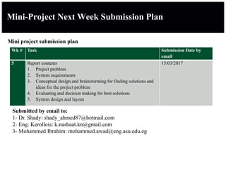
1. A mini-project submission plan for a mechatronics course, outlining the tasks and submission dates for a report on a project problem, system requirements, conceptual design, and system design.
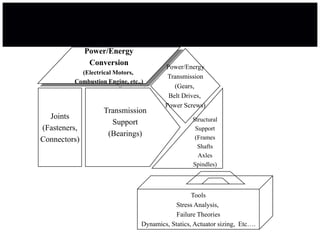
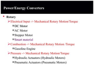
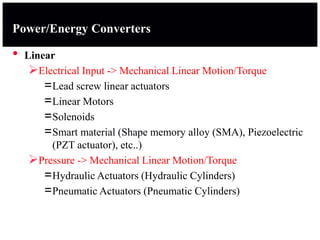
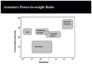
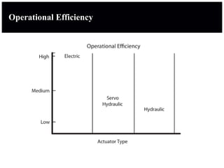
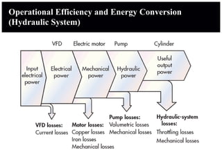
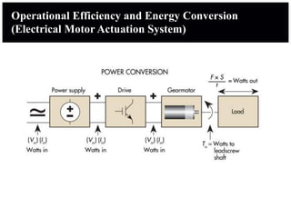
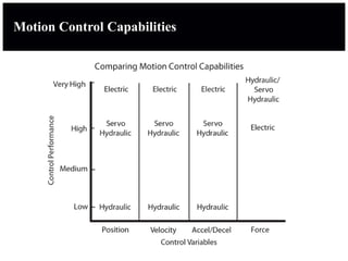
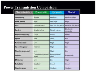
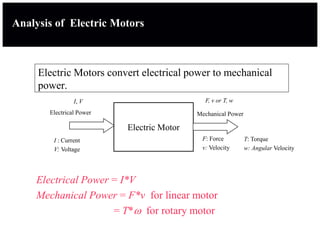
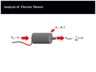
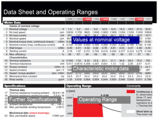
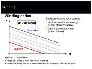
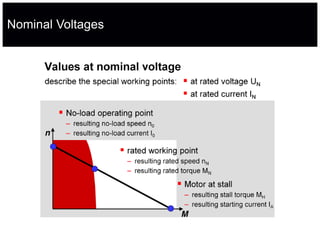
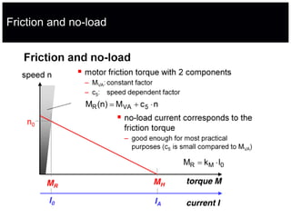
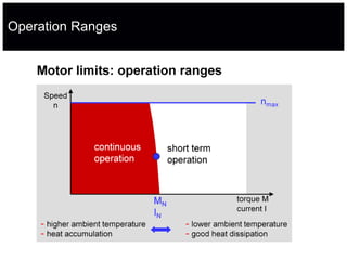
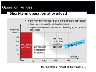
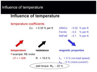
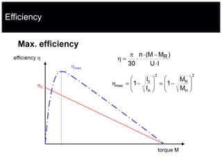
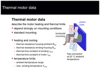
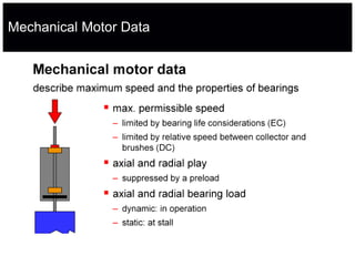
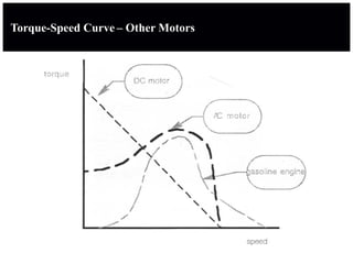
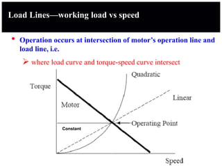
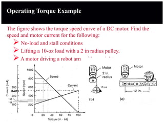
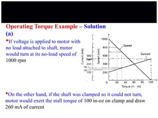
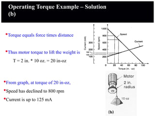
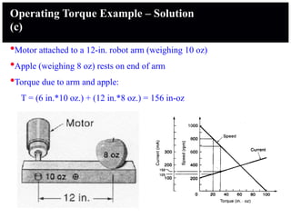
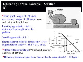
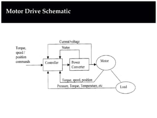
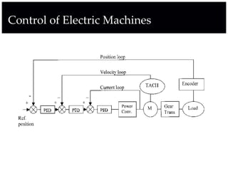
2. Different types of actuators used in mechatronics systems including electric motors, hydraulic actuators, pneumatic actuators and their operating characteristics such as torque, speed, efficiency.
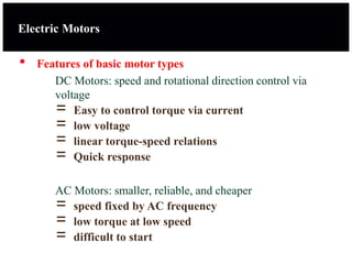
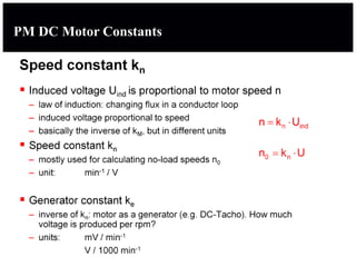
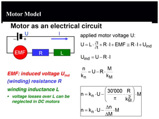
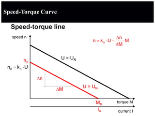
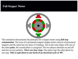
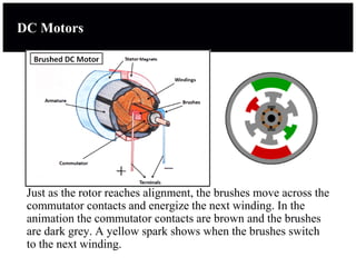
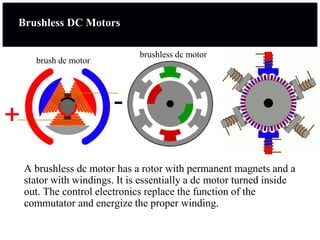
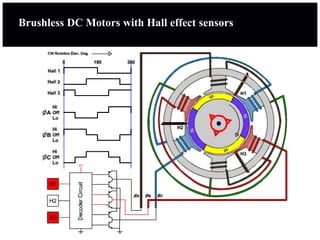
3. Details on electric motors including DC motors, AC motors, stepper motors, and brushless DC motors. It discusses motor operation, speed-torque