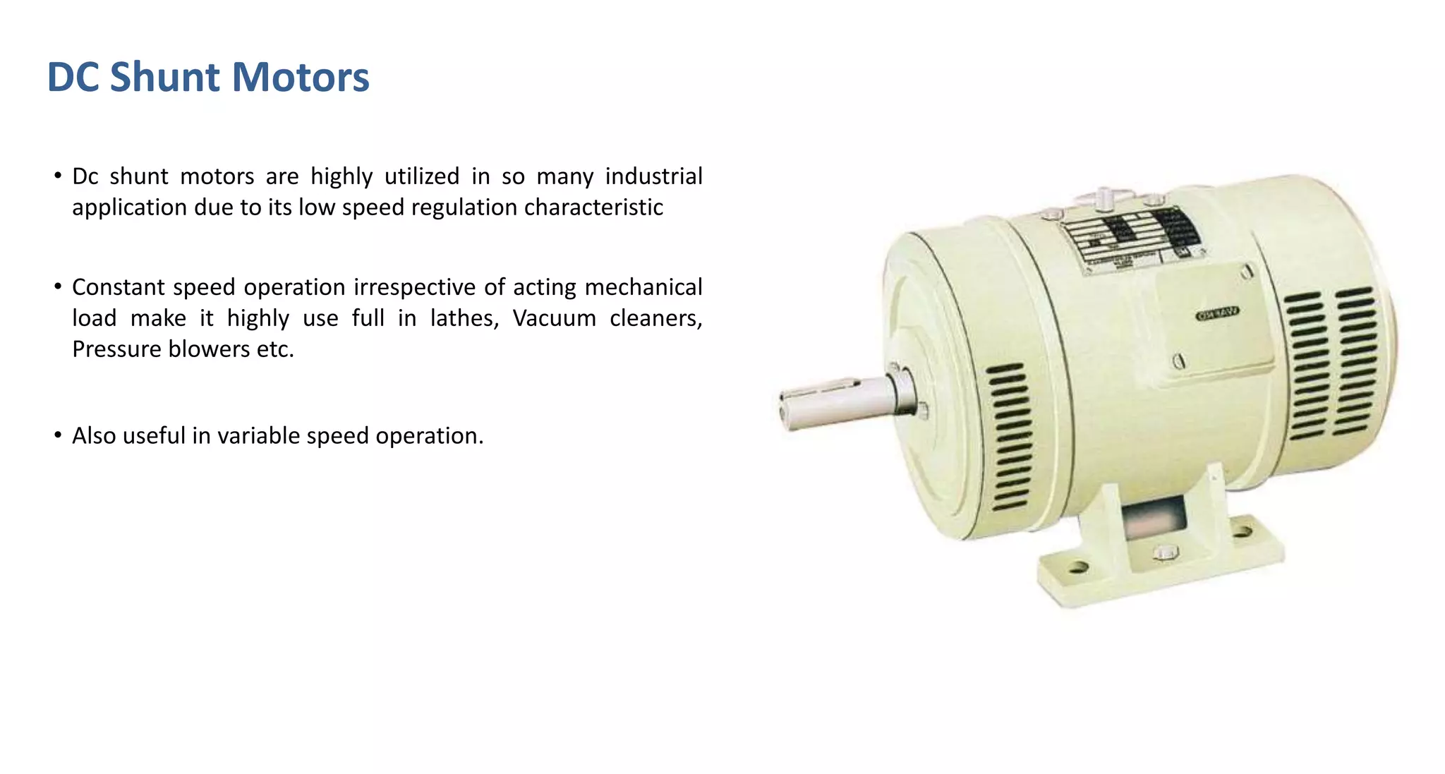
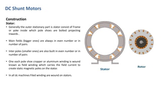
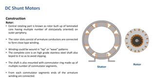
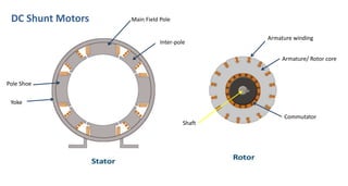
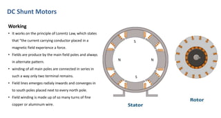
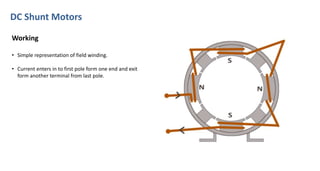
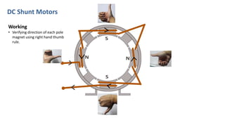
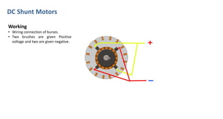
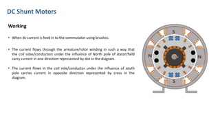
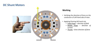
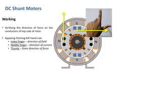
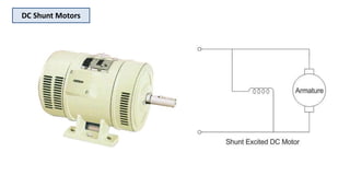
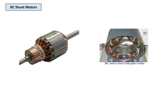
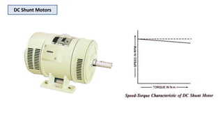
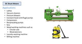
DC Shunt Motors
• Dc shunt motors are highly utilized in so many industrial
application due to its low speed regulation characteristic
• Constant speed operation irrespective of acting mechanical
load make it highly use full in lathes, Vacuum cleaners,
Pressure blowers etc.
• Also useful in variable speed operation.
DC Shunt Motors
Construction
Stator:
• Generally the outer stationary part is stator consist of Frame
or yoke inside which pole shoes are bolted projecting
Inwards .
• Main fields (bigger ones) are always in even number or in
number of pairs
• Inter poles (smaller ones) are also built in even number or in
number of pairs
• One each pole shoe cropper or aluminum winding is wound
known as field winding which carries the field current to
create static magnetic poles on the stator.
• In all dc machines Filed winding are wound on stators.
DC Shunt Motors
Construction
Rotor:
• Central rotating part is known as rotor built up of laminated
core having multiple number of slots(axially oriented) on
outer periphery.
• The rotor slots consist of armature conductors are connected
to form close type winding.
• Winding could be wound in “lap” or “wave” patterns
• The complete core is on high grade stainless steel shaft also
keyed to it so as to avoid slipping.
• The shaft is also mounted with commutator ring made up of
multiple number of commutator segments.
• From each commutator segments ends of the armature
winding are connected.
Related Videos; Click
Or Skip to Next Slide
DC Shunt Motors Main Field Pole
Inter-pole
Yoke
Pole Shoe
Armature/ Rotor core
Armature winding
Commutator
Shaft
DC Shunt Motors
Construction
• Rotor is placed inside the stator separated by small air gap and
free to rotate.
• Rotor is supported by the end cover on both side of the motor
frame by the help of bearings.
• Brushes feeds direct electric current in to the armature winding
pressing on commutator segment.
• Number of brushes are always equal to number of main poles
• Four carbon brushes are in this case of four pole shunt motor
• brushes are placed in intern polar region.
DC Shunt Motors
N
S
N
S
Working
• It works on the principle of Lorentz Law, which states
that “the current carrying conductor placed in a
magnetic field experience a force.
• Fields are produce by the main field poles and always
in alternate pattern.
• winding of all main poles are connected in series in
such a way only two terminal remains.
• Field lines emerges radialy inwards and converges in
to south poles placed next to every north pole.
• Field winding is made up of so many turns of fine
copper or aluminum wire.
DC Shunt Motors
Working
• Simple representation of field winding.
• Current enters in to first pole form one end and exit
form another terminal from last pole.
DC Shunt Motors
Working
• Verifying direction of each pole
magnet using right hand thumb
rule.
DC Shunt Motors
Working
• Wiring connection of burses.
• Two brushes are given Positive
voltage and two are given negative.
Related Videos; Click
Or Skip to Next Slide
DC Shunt Motors
Working
• When dc current is feed in to the commutator using brushes.
• The current flows through the armature/rotor winding in such a way that
the coil sides/conductors under the influence of North pole of stator/field
carry current in one direction represented by dot in the diagram.
• The current flows in the coil side/conductor under the influence of south
pole carries current in opposite direction represented by cross in the
diagram.
DC Shunt Motors
Working
• Verifying the direction of force on the
conductors of Left hand side of rotor.
• Applying Fleming left hand rule.
• Index finger – direction of field
• Middle finger – direction of
current
• Thumb – Gives direction of force
DC Shunt Motors
Working
• Verifying the direction of force on the
conductors of top side of rotor.
• Applying Fleming left hand rule.
• Index finger – direction of field
• Middle finger – direction of current
• Thumb – Gives direction of force
DC Shunt Motors
Working
• Verifying the direction of force on the
conductors of right side of rotor.
• Applying Fleming left hand rule.
• Index finger – direction of field
• Middle finger – direction of
current
• Thumb – Gives direction of force
DC Shunt Motors
Working
• Verifying the direction of force on the
conductors of bottom side of rotor.
• Applying Fleming left hand rule.
• Index finger – direction of field
• Middle finger – direction of
current
• Thumb – Gives direction of force
DC Shunt Motors
DC Shunt Motors
Working
• After verifying direction of force on all
the conductors, it could be conclude
that the rotor is getting torque in
clock wise direction
DC Shunt Motors
DC Shunt Motors
DC Shunt Motors
DC Shunt Motors
• Lathes
• Vacuum cleaners
• Pressure blowers
• Constant head centrifugal pumps
• Compressors
• Reciprocating pumps
• fans
• Wood working machines such as
• Circular saw
• Wood planners
• Laundry washing machine
• Milling machine
Applications
Related Videos; Click
Thank You

Dc shunt motors; construction and working

  • 1.
    DC Shunt Motors •Dc shunt motors are highly utilized in so many industrial application due to its low speed regulation characteristic • Constant speed operation irrespective of acting mechanical load make it highly use full in lathes, Vacuum cleaners, Pressure blowers etc. • Also useful in variable speed operation.
  • 2.
    DC Shunt Motors Construction Stator: •Generally the outer stationary part is stator consist of Frame or yoke inside which pole shoes are bolted projecting Inwards . • Main fields (bigger ones) are always in even number or in number of pairs • Inter poles (smaller ones) are also built in even number or in number of pairs • One each pole shoe cropper or aluminum winding is wound known as field winding which carries the field current to create static magnetic poles on the stator. • In all dc machines Filed winding are wound on stators.
  • 3.
    DC Shunt Motors Construction Rotor: •Central rotating part is known as rotor built up of laminated core having multiple number of slots(axially oriented) on outer periphery. • The rotor slots consist of armature conductors are connected to form close type winding. • Winding could be wound in “lap” or “wave” patterns • The complete core is on high grade stainless steel shaft also keyed to it so as to avoid slipping. • The shaft is also mounted with commutator ring made up of multiple number of commutator segments. • From each commutator segments ends of the armature winding are connected.
  • 4.
    Related Videos; Click OrSkip to Next Slide
  • 5.
    DC Shunt MotorsMain Field Pole Inter-pole Yoke Pole Shoe Armature/ Rotor core Armature winding Commutator Shaft
  • 6.
    DC Shunt Motors Construction •Rotor is placed inside the stator separated by small air gap and free to rotate. • Rotor is supported by the end cover on both side of the motor frame by the help of bearings. • Brushes feeds direct electric current in to the armature winding pressing on commutator segment. • Number of brushes are always equal to number of main poles • Four carbon brushes are in this case of four pole shunt motor • brushes are placed in intern polar region.
  • 7.
    DC Shunt Motors N S N S Working •It works on the principle of Lorentz Law, which states that “the current carrying conductor placed in a magnetic field experience a force. • Fields are produce by the main field poles and always in alternate pattern. • winding of all main poles are connected in series in such a way only two terminal remains. • Field lines emerges radialy inwards and converges in to south poles placed next to every north pole. • Field winding is made up of so many turns of fine copper or aluminum wire.
  • 8.
    DC Shunt Motors Working •Simple representation of field winding. • Current enters in to first pole form one end and exit form another terminal from last pole.
  • 9.
    DC Shunt Motors Working •Verifying direction of each pole magnet using right hand thumb rule.
  • 10.
    DC Shunt Motors Working •Wiring connection of burses. • Two brushes are given Positive voltage and two are given negative.
  • 11.
    Related Videos; Click OrSkip to Next Slide
  • 12.
    DC Shunt Motors Working •When dc current is feed in to the commutator using brushes. • The current flows through the armature/rotor winding in such a way that the coil sides/conductors under the influence of North pole of stator/field carry current in one direction represented by dot in the diagram. • The current flows in the coil side/conductor under the influence of south pole carries current in opposite direction represented by cross in the diagram.
  • 13.
    DC Shunt Motors Working •Verifying the direction of force on the conductors of Left hand side of rotor. • Applying Fleming left hand rule. • Index finger – direction of field • Middle finger – direction of current • Thumb – Gives direction of force
  • 14.
    DC Shunt Motors Working •Verifying the direction of force on the conductors of top side of rotor. • Applying Fleming left hand rule. • Index finger – direction of field • Middle finger – direction of current • Thumb – Gives direction of force
  • 15.
    DC Shunt Motors Working •Verifying the direction of force on the conductors of right side of rotor. • Applying Fleming left hand rule. • Index finger – direction of field • Middle finger – direction of current • Thumb – Gives direction of force
  • 16.
    DC Shunt Motors Working •Verifying the direction of force on the conductors of bottom side of rotor. • Applying Fleming left hand rule. • Index finger – direction of field • Middle finger – direction of current • Thumb – Gives direction of force
  • 17.
  • 18.
    DC Shunt Motors Working •After verifying direction of force on all the conductors, it could be conclude that the rotor is getting torque in clock wise direction
  • 19.
  • 20.
  • 21.
  • 22.
    DC Shunt Motors •Lathes • Vacuum cleaners • Pressure blowers • Constant head centrifugal pumps • Compressors • Reciprocating pumps • fans • Wood working machines such as • Circular saw • Wood planners • Laundry washing machine • Milling machine Applications
  • 23.