Downloaded 1,634 times


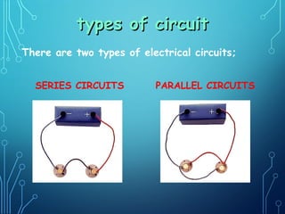
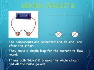
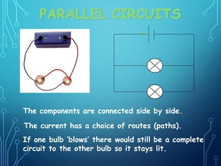


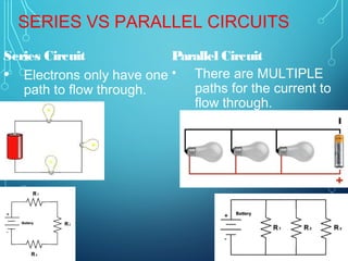
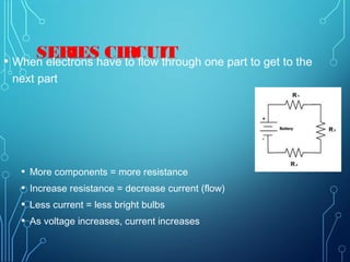
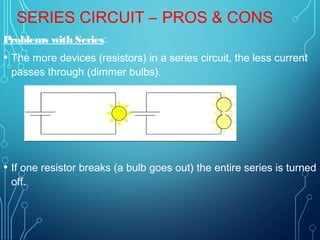
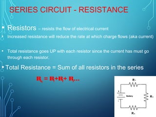
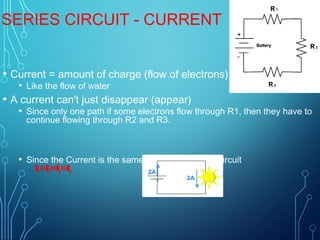
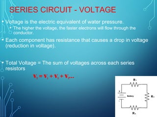
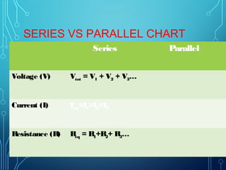
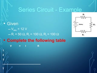

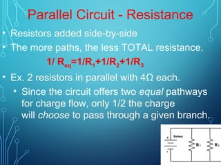
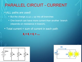
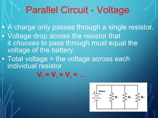
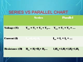
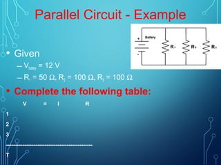


There are two types of electrical circuits: series circuits and parallel circuits. In a series circuit, the components are connected end to end in a single loop. The same current flows through each component. In a parallel circuit, the components are connected side by side, providing multiple paths for current to flow. If one component fails in a series circuit, the entire circuit is broken, while a failure in one component of a parallel circuit does not affect the others. Series circuits have higher total resistance and lower total current than parallel circuits. Home electrical systems generally use parallel circuits so that failure of one device does not disable the entire system.