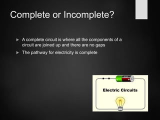
Electricity
Part I – Circuits
People
Benjamin Franklin
Thomas Edison
 Have you heard of these people?
 Why are they important?
 Benjamin Franklin
Proved that lightning was electricity by flying a
kite in a lightning storm
Helped people understand the principles of
electricity
• Thomas Edison
– Invented the electrical light bulb
What is electricity?
 Electricity is a form of energy
 It is caused by a flow of tiny particles called
electrons through a material
Electricity
Electricity is a flow of electric charges along a wire.
Electricity
Electricity is a flow of electric charges along a wire.
Electricity
Electricity is a flow of electric charges along a wire.
Electricity
Electricity is a flow of electric charges along a wire.
Electricity
Electricity is a flow of electric charges along a wire.
Electricity
Electricity is a flow of electric charges along a wire.
Electricity
Electricity is a flow of electric charges along a wire.
This flow of electric charge is called a current.
Current is measured in the units of Amps (A).
What is an Electrical Circuit?
 A circuit is an electrical device that provides a path for
electricity to flow
Complete or Incomplete?
 A complete circuit is where all the components of a
circuit are joined up and there are no gaps
 The pathway for electricity is complete
Complete or Incomplete?
 An incomplete circuit is where the pathway for
electricity is broken
 The electricity cannot flow
Circuit Diagrams
cell switch
lamp wires
Component Symbols – a cell
 The cell stores chemical
energy and transfers it to
electrical energy when a
circuit is connected.
 The long line is the positive end
 The short line is the negative
end
Battery
 When two or more cells
are connected together
we call this a Battery.
 The cells chemical energy
is used up pushing a
current round a circuit.
 It is important that each
cell faces the right way
Switch
 A switch can be open (as shown) or
closed
 When the switch is open, the circuit
is incomplete – no electricity can
flow
 What happens when the switch is
closed?
Bulb / Lamp
 The lamp lights up when
electricity flows through it
 What would happen to a
lamp if there was an open
switch in the circuit?
Wires
The wires which carry electricity consist of two parts:
• The metal wires (conductor).
• The plastic coating around the metal wires (insulator).
• Prevents people from being electrocuted.
wires
Voltmeter
 The voltmeter measures the
voltage of the circuit
 We will discuss this in
another lesson
Ammeter
 The ammeter measures
the current in the circuit
 We will discuss this in
another lesson
Resistor
 A resistor can change the amount of current in a circuit
 In a variable resistor, the resistance can be changed.
Resistance
Variable resistors
Look at Figure 17.6 on page 207.
Path of current flow
Terminal A  metal bar  sliding contact  coils of wire  Terminal B
Variable resistors
Look at Figure 17.6 on page 207.
The sliding contact can be adjusted so that the current passes through only
a few coils of wire or many coils of wire.
If the sliding contact is near Terminal A : current passes through many
coils of wire = high resistance
If the sliding contact is near Terminal B: current passes through a few
coils of wire = low resistance
Variable resistors
Turn the dial here for
low resistance higher resistance
Fuse
 A fuse is a safety device
 When the current is too
high, the fuse breaks
Example
The wire inside a 3A fuse will melt when the current is greater than 3A.
Motor
 A motor can be fitted into
a circuit
 What do you think
happens to a motor in a
complete circuit?
Circuit Symbols
Voltmeter
Ammeter
Variable Resistor
Switch
Bulb
Motor
Cell
Battery
types of circuit
There are two types of electrical circuits;
SERIES CIRCUITS PARALLEL CIRCUITS
The components are connected end-to-end, one
after the other.
They make a simple loop for the current to flow
round.
SERIES CIRCUITS
If one bulb ‘blows’ it breaks the whole circuit and
all the bulbs go out.
PARALLEL CIRCUITS
The current has a choice of routes (paths).
The components are connected side by side.
If one bulb ‘blows’ there would still be a complete circuit
to the other bulb so it stays lit.
measuring current
Electric current is measured in amps (A) using
an ammeter connected in series in the circuit.
A
measuring current
A A
This is how we draw an ammeter in a circuit.
SERIES CIRCUIT PARALLEL CIRCUIT
measuring current
SERIES CIRCUIT
PARALLEL CIRCUIT
• current is the same
at all points in the
circuit.
6A 6A
6A
• current is shared
between the
components
4A
4A
3A
1A
copy the following circuits and fill in the
missing ammeter readings.
?
?
4A
4A
4A
3A
?
?
1A
?
3A
1A
1A
measuring voltage
The ‘electrical push’ which the cell gives to the current
is called the voltage. It is measured in volts (V) on a
voltmeter
V
Different cells produce different voltages.
The bigger the voltage supplied by the cell, the bigger
the current (the cell gives a bigger push to the
electrons).
measuring voltage
measuring voltage
Unlike an ammeter a voltmeter is connected across
the components (in parallel)
Scientist usually use the term Potential Difference
(pd) when they talk about voltage.
Final GPE
Initial GPE
Potential
Difference
pd
measuring voltage
V
This is how we draw a voltmeter in a circuit.
SERIES CIRCUIT PARALLEL CIRCUIT
V
V
measuring voltage
V
V
V
series circuit
1.5V
• voltage is shared between the components
1.5V
3V
• voltage is the same in all parts of the circuit.
3V
parallel circuit
3V
3V
measuring current & voltage
V V
6V
4A
A
A
a)
measuring current & voltage
V
V
6V
4A A
A
A
b)
answers
3V 3V
6V
4A 4A
6V
6V
6V
4A 4A
2A
2A
4A
a) b)

Electricity