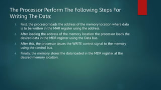
Input/Output Interface in Microprocessors
PRESENTED BY: PRESENTED TO:
RAJESH KUMAR YADAV NISHAN KHANAL
SEMESTER= THIRD
Content:
 Introduction to Input/Output Interface (I/O) in Microprocessors
 Importance of I/O interface in Microprocessors
 Internal communication
 Modes of communication
 Communication Method
 RS-232C
 IEE488-1978 General purpose interface standard
 Parallel Interfacing
Introduction to Input/Output Interface (I/O) in
Microprocessors
 Mechanism that enables communication between the microprocessor and
the outside world.
 Serves as the gateway for data exchange between the microprocessor and
various input/output devices such as sensors, actuators, display units, and
other peripherals.
 Plays a crucial role in the performance of a microprocessor-based system,
and its design can significantly impact the efficiency of the overall system
Importance of I/O interface in
Microprocessors
 Communication with Peripherals:
1. Enables the microprocessor to communicate with various input/output.
 Efficient Data Transfer:
1. Significantly impact the efficiency of the data transfer between the
microprocessor and peripherals
 Resource Management:
1. Manages the resources required by the input/output devices, such as
memory, processing power
 Flexibility:
1. Allows the system to be flexible and scalable, enabling the addition or
removal of peripherals without the need to redesign the entire system
Internal communication
 To transport data between memory and I/O devices, the computer
system's CPU interfaces with them.
 The CPU communicates with memory and I/O devices in distinct ways.
Either directly or through the Cache memory, the CPU can connect With
the memory.
 communication between the CPU and the I/O devices, on the other hand,
is normally accomplished through the use of an interface.
 The internal communication of a computer processor can be separated
into two categories:
1. Processor To Memory Communication
2. Processor To I/O Devices Communication
Processor To Memory Communication
 The direct communication between the processor and memory of the computer system
is implemented with the help of two registers. Memory Address register (MAR) and
Memory Buffer register (MHR).
 The processor can interact with the memory of the computer system for reading data
from the memory as well as for writing data on to the memory.
 The MAR and MBR register play a very important role in implementing this type of
communication. These registers arc the special purpose register of the processor.
 The Processor Perform The Following Steps To Read The Data:
1. First, the processor loads the address of the memory location from where data is in the
reader into the MAR register using the address bus.
2. . After loading the address of the memory location the processor issues the READ
control signal through the control bus. The control bus is used to carry the commands
issued by the processor and status signals are generated by the various devices in
response to these commands
3. After receiving the READ control signal the memory loads the data into the MDR
register from the location specified in the MAR register using the Data bus.
4. . Finally, the data is transferred to the processor
The Processor Perform The Following Steps For
Writing The Data:
1. First, the processor loads the address of the memory location where data
is to be written in the MAR register using the address.
2. After loading the address of the memory location the processor loads the
desired data in the MDR register using the Data bus.
3. After this, the processor issues the WRITE control signal to the memory
using the control bus.
4. Finally, the memory stores the data loaded in the MDR register at the
desired memory location.
Processor To I/O Devices
Communication
 Some Steps Are Performed While Transferring Data From I/0 Devices:
1. The data is to be transferred is placed on the data bus by the input
devices which transfer single bytes of data at a time.
2. The input devices then issue the data valid signal through the devices
control bus to the data register, including that the data is available on the
data bus
3. As the data register now holds the data the For the flog bit of the same
register in the interface unit
4. The processor the now issue an I/O read signal to the data registers in the
interface unit.
5. The data register then places the data on the data on the data bus
connected to the processor of the computer system.
Some Steps Are Performed While Transferring Data To
Output Devices:
1. The processor laces the data that needs to be transferred on the data bus
connected to the data register of the interface unit.
2. The CPU also places the address of the output devices on the devices address
bus.
3. After placing the address and data on the appropriate buses, CPU issue the
I/O write signal, which writes the data on the data register
4. The data register of the interface unit issue a data accepted signal through
the control bus to the processor
5. The interface unit then places the data stored in the data register on to the
data bus connected to the device controller of the output device
6. The output devices then receive the data and send to acknowledgment signal
to the processor
Mode of Communications
 Simplex Mode:
It is a one way communication in which one part is always a transmitter
which transmits information and the other part is always a receiver, which
always receives the information. For example: AM, FM, TV broadcasting, etc.
 Half Duplex Mode:
It is both ways communication alternatively over single channel. For
example: walkie-talkie.
 Both ways communication simultaneously over different channels is called
full duplex mode of communication. For example: mobile phone
Communication Method
 There are two methods of communication. They are
 Parallel Communication:
 When a word of "n" bit is to be transmitted in parallel, each bit is
transmitted on a separate line along with a common ground line. The
status of each line is measured with respect to the common ground line.
Thus, a channel comprises of n+l wires, such type of communication is
greatly used for short distance communication such as printer
interconnected with processor. The primary advantage of parallel
communication is its higher speed.
 Suppose the time between two successive samples Of "t" seconds and two
successive words are 10010100 and 11000101 (say), and then the flow of
data on the parallel lines called channel or bus. This is shown in figure
below. The time required to transmit one word (8-bitJ will be equal to time
taken to transmit a bit.
Serial Communication
 In serial communication, each bit of a data word is sent in succession, one
at a time over a single pair of wires (and three wires in case of full duplex
operation). A parallel to serial data converter is used to convert the
incoming parallel data into serial form, and then data is sent out with LSB
(Do) first and MSB coming as the last. It is comparatively slower than
parallel communication but commonly used for long distance
communication
 There are two types of serial data transfers:
 1)Asynchronous Transfer
 2) Synchronous Transfer
1)Asynchronous Transfer
 In this type of transmission. the receiving device does not need to be
synchronized with transmitting device. The transmitting device can send
one or more data units when it is ready to send. Each data unit must be
formatted.
 In other words, each data unit (word) must contain a start bit and a Stop
bit, indicating the beginning and end of each data unit (word). In
asynchronous transmission, the data message is sent at a time. When no
data are sent over a line it is maintained at idle value (i.e. at logic 1).
Synchronous Transfer
 Synchronous communication is used for transferring large amount of data
at a stretch without frequent start or stop bit. In this system, also the line is
maintained at the idle value when no data is being transmitted. The
transmission begins with a block of header which is pre-determined
pattern of bits. The receiver identifies the pattern and gets ready to receive
the characters.
 The transmitter sends the data character by character bit by bit. After
sending all the characters the transmitter sends another pattern
(sequence) ofbits to indicate the end of transmission. This format is
generally used for high speed transmission i.e. more than 20kbps.
RS-232C
 RS - 232C is most widely used serial communication standard. The RS -
232C interface is the Electronic Industries Association (EIA) standard for
the interchanges of serial binary data between two devices, computers
with telephone line modems.
 Three wires are sufficient to send data, receive data and ground. Modems
are referred as Data Communication Equipment (DCE). The terminals or
computers that are sending and receiving the data are called Data
Terminal Equipment (DTE).
 The DTE is capable of sending and receiving the data through a serial
interface
 DCE is used to provide facility of serial data communication
IEEE 488 - 1978 General Purpose
Interface Standard
 The IEEE-488 bus was developed to connect and control programmable instruments,
and to provide a standard interface for communication between instruments from
different sources
 Hewlett-Packard originally developed the interfacing technique, and called it HP-IB
(Hewlett Packard Instrument Bus). The interface quickly gained popularity in the
computer industry. Because the interface was so versatile, the IEEE committee renamed
it GPIB (General Purpose interface Bus).
 IEEE-488 allows up to 15 devices to share a single 8bit parallel electrical bus by daisy
chaining
 The slowest device participates in control and data transfer handshakes to determine
the speed Of the transaction. The maximum data rate is about one Mbyte/sec in the
original standard, and about 8 Mbyte/sec with IEEE488.1-2003 (IIS-488).
 Within IEEE 488, the equipment on the bus falls into three categories, although items
can fulfill more than one function
Controller
 The controller is the entity that controls the operation Of the bus. It is
usually a computer and it signals that instruments are to perform the
various functions. The GPIB controller also ensures that no conflicts occur
on the bus
 If two talkers tried to talk at the same time then data would become
corrupted and the operation of the whole system would be seriously
impaired. It is possible for multiple controllers to share the same bus; but
only one can act as a controller at any particular time
Listener
 A listener is an entity connected to the bus that accepts instructions from
the bus. An example of a listener is an item such as a printer that only
accepts data from the bus
Talker
 A talker is a device that is capable Of sending data or instructions to Other
devices. A voltmeter would be a talker since it can send voltage readings
to another device.
 Many items Will fulfill more than one function. For example a voltmeter
which is controlled over the bus will act as a listener when it is being set
up, and then when it is returning the data, it will act a talker. As such it is
known as a talker / listener
Features
 Parallel 8 — bit data path for data read and write
 Three flow control lines (handshake signals)
 Five special lines for control of bus and interrupts
 A maximum of 15 instruments connected to a common bus Up to 20m
maximum cable length
Advantages
 Simple & standard hardware interface
 Interface present on many bench instruments
 Rugged connectors & connectors used (although some insulation
displacement cables appear occasionally).
 Possible to connect multiple instruments to a single controller
Disadvantages
 Bully connectors
 Cable reliability poor - often as a result of the bulky cables
 Low bandwidth - slow compared to more modern interfaces
 Basic IEEE 422 does not mandate a command language (SCPI used in later
implementations but not included on all instruments
Parallel Interfacing
 There are two ways to interface 8085 with input/output devices in parallel
data transfer mode. They are
 1) Memory Mapped Input/output: It considers them like any Other
memory location. They are assigned a 16-bit address within the address
range of the 8085. The exchange of data with these devices follows the
transfer Of data With memory. The users use the same instructions used
for memory
 2) Input/output Mapped Input/output: It treats them separately from
memory input/output devices are assigned as "Port Number" within the 8-
bit address range of OOH to FFH. The users in this case would access these
devices using the IN and OUT instructions
THANK YOU

io intweface.pptx

  • 1.
    Input/Output Interface inMicroprocessors PRESENTED BY: PRESENTED TO: RAJESH KUMAR YADAV NISHAN KHANAL SEMESTER= THIRD
  • 2.
    Content:  Introduction toInput/Output Interface (I/O) in Microprocessors  Importance of I/O interface in Microprocessors  Internal communication  Modes of communication  Communication Method  RS-232C  IEE488-1978 General purpose interface standard  Parallel Interfacing
  • 3.
    Introduction to Input/OutputInterface (I/O) in Microprocessors  Mechanism that enables communication between the microprocessor and the outside world.  Serves as the gateway for data exchange between the microprocessor and various input/output devices such as sensors, actuators, display units, and other peripherals.  Plays a crucial role in the performance of a microprocessor-based system, and its design can significantly impact the efficiency of the overall system
  • 4.
    Importance of I/Ointerface in Microprocessors  Communication with Peripherals: 1. Enables the microprocessor to communicate with various input/output.  Efficient Data Transfer: 1. Significantly impact the efficiency of the data transfer between the microprocessor and peripherals  Resource Management: 1. Manages the resources required by the input/output devices, such as memory, processing power  Flexibility: 1. Allows the system to be flexible and scalable, enabling the addition or removal of peripherals without the need to redesign the entire system
  • 5.
    Internal communication  Totransport data between memory and I/O devices, the computer system's CPU interfaces with them.  The CPU communicates with memory and I/O devices in distinct ways. Either directly or through the Cache memory, the CPU can connect With the memory.  communication between the CPU and the I/O devices, on the other hand, is normally accomplished through the use of an interface.  The internal communication of a computer processor can be separated into two categories: 1. Processor To Memory Communication 2. Processor To I/O Devices Communication
  • 6.
    Processor To MemoryCommunication  The direct communication between the processor and memory of the computer system is implemented with the help of two registers. Memory Address register (MAR) and Memory Buffer register (MHR).  The processor can interact with the memory of the computer system for reading data from the memory as well as for writing data on to the memory.  The MAR and MBR register play a very important role in implementing this type of communication. These registers arc the special purpose register of the processor.  The Processor Perform The Following Steps To Read The Data: 1. First, the processor loads the address of the memory location from where data is in the reader into the MAR register using the address bus. 2. . After loading the address of the memory location the processor issues the READ control signal through the control bus. The control bus is used to carry the commands issued by the processor and status signals are generated by the various devices in response to these commands 3. After receiving the READ control signal the memory loads the data into the MDR register from the location specified in the MAR register using the Data bus. 4. . Finally, the data is transferred to the processor
  • 7.
    The Processor PerformThe Following Steps For Writing The Data: 1. First, the processor loads the address of the memory location where data is to be written in the MAR register using the address. 2. After loading the address of the memory location the processor loads the desired data in the MDR register using the Data bus. 3. After this, the processor issues the WRITE control signal to the memory using the control bus. 4. Finally, the memory stores the data loaded in the MDR register at the desired memory location.
  • 8.
    Processor To I/ODevices Communication  Some Steps Are Performed While Transferring Data From I/0 Devices: 1. The data is to be transferred is placed on the data bus by the input devices which transfer single bytes of data at a time. 2. The input devices then issue the data valid signal through the devices control bus to the data register, including that the data is available on the data bus 3. As the data register now holds the data the For the flog bit of the same register in the interface unit 4. The processor the now issue an I/O read signal to the data registers in the interface unit. 5. The data register then places the data on the data on the data bus connected to the processor of the computer system.
  • 9.
    Some Steps ArePerformed While Transferring Data To Output Devices: 1. The processor laces the data that needs to be transferred on the data bus connected to the data register of the interface unit. 2. The CPU also places the address of the output devices on the devices address bus. 3. After placing the address and data on the appropriate buses, CPU issue the I/O write signal, which writes the data on the data register 4. The data register of the interface unit issue a data accepted signal through the control bus to the processor 5. The interface unit then places the data stored in the data register on to the data bus connected to the device controller of the output device 6. The output devices then receive the data and send to acknowledgment signal to the processor
  • 10.
    Mode of Communications Simplex Mode: It is a one way communication in which one part is always a transmitter which transmits information and the other part is always a receiver, which always receives the information. For example: AM, FM, TV broadcasting, etc.  Half Duplex Mode: It is both ways communication alternatively over single channel. For example: walkie-talkie.  Both ways communication simultaneously over different channels is called full duplex mode of communication. For example: mobile phone
  • 11.
    Communication Method  Thereare two methods of communication. They are  Parallel Communication:  When a word of "n" bit is to be transmitted in parallel, each bit is transmitted on a separate line along with a common ground line. The status of each line is measured with respect to the common ground line. Thus, a channel comprises of n+l wires, such type of communication is greatly used for short distance communication such as printer interconnected with processor. The primary advantage of parallel communication is its higher speed.  Suppose the time between two successive samples Of "t" seconds and two successive words are 10010100 and 11000101 (say), and then the flow of data on the parallel lines called channel or bus. This is shown in figure below. The time required to transmit one word (8-bitJ will be equal to time taken to transmit a bit.
  • 12.
    Serial Communication  Inserial communication, each bit of a data word is sent in succession, one at a time over a single pair of wires (and three wires in case of full duplex operation). A parallel to serial data converter is used to convert the incoming parallel data into serial form, and then data is sent out with LSB (Do) first and MSB coming as the last. It is comparatively slower than parallel communication but commonly used for long distance communication  There are two types of serial data transfers:  1)Asynchronous Transfer  2) Synchronous Transfer
  • 13.
    1)Asynchronous Transfer  Inthis type of transmission. the receiving device does not need to be synchronized with transmitting device. The transmitting device can send one or more data units when it is ready to send. Each data unit must be formatted.  In other words, each data unit (word) must contain a start bit and a Stop bit, indicating the beginning and end of each data unit (word). In asynchronous transmission, the data message is sent at a time. When no data are sent over a line it is maintained at idle value (i.e. at logic 1).
  • 14.
    Synchronous Transfer  Synchronouscommunication is used for transferring large amount of data at a stretch without frequent start or stop bit. In this system, also the line is maintained at the idle value when no data is being transmitted. The transmission begins with a block of header which is pre-determined pattern of bits. The receiver identifies the pattern and gets ready to receive the characters.  The transmitter sends the data character by character bit by bit. After sending all the characters the transmitter sends another pattern (sequence) ofbits to indicate the end of transmission. This format is generally used for high speed transmission i.e. more than 20kbps.
  • 15.
    RS-232C  RS -232C is most widely used serial communication standard. The RS - 232C interface is the Electronic Industries Association (EIA) standard for the interchanges of serial binary data between two devices, computers with telephone line modems.  Three wires are sufficient to send data, receive data and ground. Modems are referred as Data Communication Equipment (DCE). The terminals or computers that are sending and receiving the data are called Data Terminal Equipment (DTE).  The DTE is capable of sending and receiving the data through a serial interface  DCE is used to provide facility of serial data communication
  • 16.
    IEEE 488 -1978 General Purpose Interface Standard  The IEEE-488 bus was developed to connect and control programmable instruments, and to provide a standard interface for communication between instruments from different sources  Hewlett-Packard originally developed the interfacing technique, and called it HP-IB (Hewlett Packard Instrument Bus). The interface quickly gained popularity in the computer industry. Because the interface was so versatile, the IEEE committee renamed it GPIB (General Purpose interface Bus).  IEEE-488 allows up to 15 devices to share a single 8bit parallel electrical bus by daisy chaining  The slowest device participates in control and data transfer handshakes to determine the speed Of the transaction. The maximum data rate is about one Mbyte/sec in the original standard, and about 8 Mbyte/sec with IEEE488.1-2003 (IIS-488).  Within IEEE 488, the equipment on the bus falls into three categories, although items can fulfill more than one function
  • 17.
    Controller  The controlleris the entity that controls the operation Of the bus. It is usually a computer and it signals that instruments are to perform the various functions. The GPIB controller also ensures that no conflicts occur on the bus  If two talkers tried to talk at the same time then data would become corrupted and the operation of the whole system would be seriously impaired. It is possible for multiple controllers to share the same bus; but only one can act as a controller at any particular time
  • 18.
    Listener  A listeneris an entity connected to the bus that accepts instructions from the bus. An example of a listener is an item such as a printer that only accepts data from the bus
  • 19.
    Talker  A talkeris a device that is capable Of sending data or instructions to Other devices. A voltmeter would be a talker since it can send voltage readings to another device.  Many items Will fulfill more than one function. For example a voltmeter which is controlled over the bus will act as a listener when it is being set up, and then when it is returning the data, it will act a talker. As such it is known as a talker / listener
  • 20.
    Features  Parallel 8— bit data path for data read and write  Three flow control lines (handshake signals)  Five special lines for control of bus and interrupts  A maximum of 15 instruments connected to a common bus Up to 20m maximum cable length
  • 21.
    Advantages  Simple &standard hardware interface  Interface present on many bench instruments  Rugged connectors & connectors used (although some insulation displacement cables appear occasionally).  Possible to connect multiple instruments to a single controller
  • 22.
    Disadvantages  Bully connectors Cable reliability poor - often as a result of the bulky cables  Low bandwidth - slow compared to more modern interfaces  Basic IEEE 422 does not mandate a command language (SCPI used in later implementations but not included on all instruments
  • 23.
    Parallel Interfacing  Thereare two ways to interface 8085 with input/output devices in parallel data transfer mode. They are  1) Memory Mapped Input/output: It considers them like any Other memory location. They are assigned a 16-bit address within the address range of the 8085. The exchange of data with these devices follows the transfer Of data With memory. The users use the same instructions used for memory  2) Input/output Mapped Input/output: It treats them separately from memory input/output devices are assigned as "Port Number" within the 8- bit address range of OOH to FFH. The users in this case would access these devices using the IN and OUT instructions
  • 24.