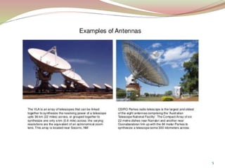
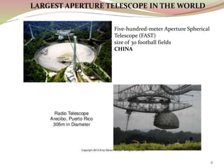
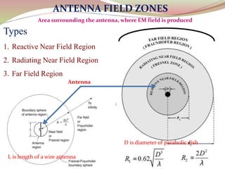
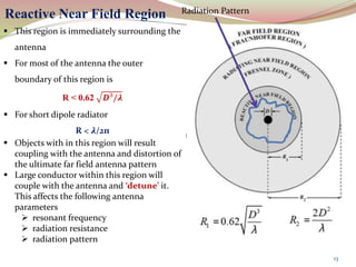
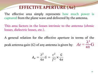
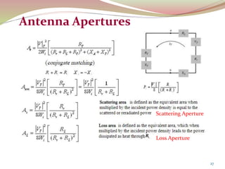
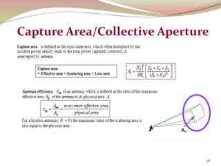
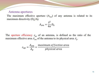
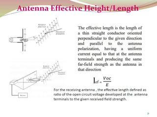
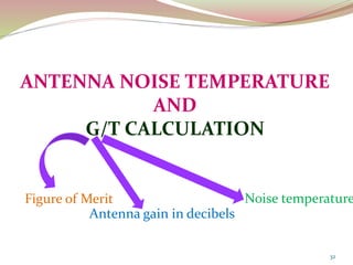
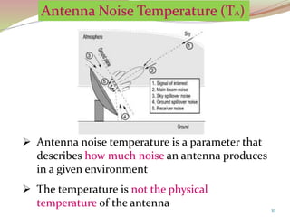
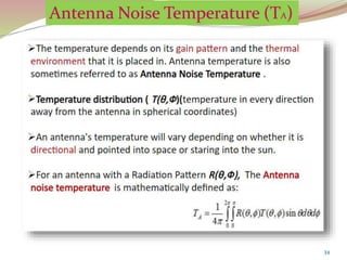
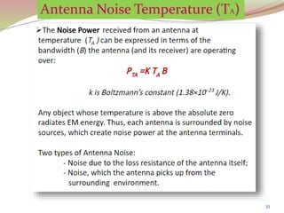
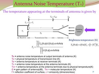
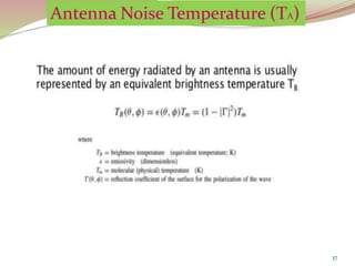
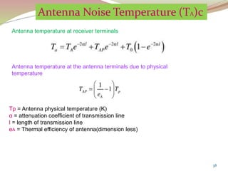
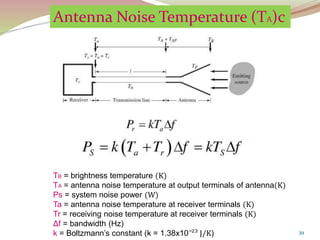
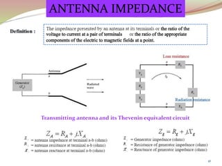
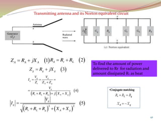
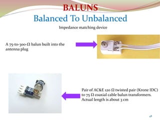
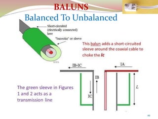
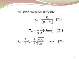
In telecommunication, an eye pattern, also known as an eye diagram, is an oscilloscope display in which a digital signal from a receiver is repetitively sampled and applied to the vertical input, while the data rate is used to trigger the horizontal sweep. It is so called because, for several types of coding, the pattern looks like a series of eyes between a pair of rails. It is a tool for the evaluation of the combined effects of channel noise and intersymbol interference on the performance of a baseband pulse-transmission system. It is the synchronised superposition of all possible realisations of the signal of interest viewed within a particular signaling interval.
In communication system, intersymbol interference (ISI) is a form of distortion of a signal in which one symbol interferes with subsequent symbols. This is an unwanted phenomenon as the previous symbols have similar effect as noise, thus making the communication less reliable.
In communication system, the Nyquist ISI criterion describes the conditions which when satisfied by a communication channel (including responses of transmit and receive filters), result in no intersymbol interference(ISI). It provides a method for constructing band-limited functions to overcome the effects of intersymbol interference.
Base band transmission
*Wave form representation of binary digits
*PCM, DPCM, DM, ADM systems
*Detection of signals in Gaussian noise
*Matched filter - Application of matched filter
*Error probability performance of binary signaling
*Multilevel base band transmission
*Inter symbol interference
*Eye pattern
*Companding
*A law and μ law
*Correlation receiver
It is a digital representation of an analog signal that takes samples of the amplitude of the analog signal at regular intervals. The sampled analog data is changed to, and then represented by, binary data.
Introduction to basics of wireless networks such as
• Radio waves & wireless signal encoding techniques
• Wireless networking issues & constraints
• Wireless internetworking devices
The Presentation includes Basics of Non - Uniform Quantization, Companding and different Pulse Code Modulation Techniques. Comparison of Various PCM techniques is done considering various Parameters in Communication Systems.
By completing this presentation will be have a clear idea about Antenna's working principles, Antenna's Types & Antenna's Parameters. At the end to this document you'll have a brief idea about Antenna's Tilt vs Distance Calculation & Cluster wise optimum Antenna Selection procedure. Impact of antenna PIM & VSWR have been described elaborately in this document as well.
In radio and electronics, an antenna is an electrical device which converts electric power into radio waves, and vice versa. It is usually used with a radio transmitter or radio receiver. In transmission, a radio transmitter supplies an electric current oscillating at radio frequency to the antenna's terminals, and the antenna radiates the energy from the current as electromagnetic waves (radio waves). In reception, an antenna intercepts some of the power of an electromagnetic wave in order to produce a tiny voltage at its terminals, that is applied to a receiver to be amplified.
Explore the innovative world of trenchless pipe repair with our comprehensive guide, "The Benefits and Techniques of Trenchless Pipe Repair." This document delves into the modern methods of repairing underground pipes without the need for extensive excavation, highlighting the numerous advantages and the latest techniques used in the industry.
Learn about the cost savings, reduced environmental impact, and minimal disruption associated with trenchless technology. Discover detailed explanations of popular techniques such as pipe bursting, cured-in-place pipe (CIPP) lining, and directional drilling. Understand how these methods can be applied to various types of infrastructure, from residential plumbing to large-scale municipal systems.
Ideal for homeowners, contractors, engineers, and anyone interested in modern plumbing solutions, this guide provides valuable insights into why trenchless pipe repair is becoming the preferred choice for pipe rehabilitation. Stay informed about the latest advancements and best practices in the field.
CFD Simulation of By-pass Flow in a HRSG module by R&R Consult.pptxR&R Consult
CFD analysis is incredibly effective at solving mysteries and improving the performance of complex systems!
Here's a great example: At a large natural gas-fired power plant, where they use waste heat to generate steam and energy, they were puzzled that their boiler wasn't producing as much steam as expected.
R&R and Tetra Engineering Group Inc. were asked to solve the issue with reduced steam production.
An inspection had shown that a significant amount of hot flue gas was bypassing the boiler tubes, where the heat was supposed to be transferred.
R&R Consult conducted a CFD analysis, which revealed that 6.3% of the flue gas was bypassing the boiler tubes without transferring heat. The analysis also showed that the flue gas was instead being directed along the sides of the boiler and between the modules that were supposed to capture the heat. This was the cause of the reduced performance.
Based on our results, Tetra Engineering installed covering plates to reduce the bypass flow. This improved the boiler's performance and increased electricity production.
It is always satisfying when we can help solve complex challenges like this. Do your systems also need a check-up or optimization? Give us a call!
Work done in cooperation with James Malloy and David Moelling from Tetra Engineering.
More examples of our work https://www.r-r-consult.dk/en/cases-en/
About
Indigenized remote control interface card suitable for MAFI system CCR equipment. Compatible for IDM8000 CCR. Backplane mounted serial and TCP/Ethernet communication module for CCR remote access. IDM 8000 CCR remote control on serial and TCP protocol.
• Remote control: Parallel or serial interface.
• Compatible with MAFI CCR system.
• Compatible with IDM8000 CCR.
• Compatible with Backplane mount serial communication.
• Compatible with commercial and Defence aviation CCR system.
• Remote control system for accessing CCR and allied system over serial or TCP.
• Indigenized local Support/presence in India.
• Easy in configuration using DIP switches.
Technical Specifications
Indigenized remote control interface card suitable for MAFI system CCR equipment. Compatible for IDM8000 CCR. Backplane mounted serial and TCP/Ethernet communication module for CCR remote access. IDM 8000 CCR remote control on serial and TCP protocol.
Key Features
Indigenized remote control interface card suitable for MAFI system CCR equipment. Compatible for IDM8000 CCR. Backplane mounted serial and TCP/Ethernet communication module for CCR remote access. IDM 8000 CCR remote control on serial and TCP protocol.
• Remote control: Parallel or serial interface
• Compatible with MAFI CCR system
• Copatiable with IDM8000 CCR
• Compatible with Backplane mount serial communication.
• Compatible with commercial and Defence aviation CCR system.
• Remote control system for accessing CCR and allied system over serial or TCP.
• Indigenized local Support/presence in India.
Application
• Remote control: Parallel or serial interface.
• Compatible with MAFI CCR system.
• Compatible with IDM8000 CCR.
• Compatible with Backplane mount serial communication.
• Compatible with commercial and Defence aviation CCR system.
• Remote control system for accessing CCR and allied system over serial or TCP.
• Indigenized local Support/presence in India.
• Easy in configuration using DIP switches.
Hybrid optimization of pumped hydro system and solar- Engr. Abdul-Azeez.pdffxintegritypublishin
Advancements in technology unveil a myriad of electrical and electronic breakthroughs geared towards efficiently harnessing limited resources to meet human energy demands. The optimization of hybrid solar PV panels and pumped hydro energy supply systems plays a pivotal role in utilizing natural resources effectively. This initiative not only benefits humanity but also fosters environmental sustainability. The study investigated the design optimization of these hybrid systems, focusing on understanding solar radiation patterns, identifying geographical influences on solar radiation, formulating a mathematical model for system optimization, and determining the optimal configuration of PV panels and pumped hydro storage. Through a comparative analysis approach and eight weeks of data collection, the study addressed key research questions related to solar radiation patterns and optimal system design. The findings highlighted regions with heightened solar radiation levels, showcasing substantial potential for power generation and emphasizing the system's efficiency. Optimizing system design significantly boosted power generation, promoted renewable energy utilization, and enhanced energy storage capacity. The study underscored the benefits of optimizing hybrid solar PV panels and pumped hydro energy supply systems for sustainable energy usage. Optimizing the design of solar PV panels and pumped hydro energy supply systems as examined across diverse climatic conditions in a developing country, not only enhances power generation but also improves the integration of renewable energy sources and boosts energy storage capacities, particularly beneficial for less economically prosperous regions. Additionally, the study provides valuable insights for advancing energy research in economically viable areas. Recommendations included conducting site-specific assessments, utilizing advanced modeling tools, implementing regular maintenance protocols, and enhancing communication among system components.
Hierarchical Digital Twin of a Naval Power SystemKerry Sado
A hierarchical digital twin of a Naval DC power system has been developed and experimentally verified. Similar to other state-of-the-art digital twins, this technology creates a digital replica of the physical system executed in real-time or faster, which can modify hardware controls. However, its advantage stems from distributing computational efforts by utilizing a hierarchical structure composed of lower-level digital twin blocks and a higher-level system digital twin. Each digital twin block is associated with a physical subsystem of the hardware and communicates with a singular system digital twin, which creates a system-level response. By extracting information from each level of the hierarchy, power system controls of the hardware were reconfigured autonomously. This hierarchical digital twin development offers several advantages over other digital twins, particularly in the field of naval power systems. The hierarchical structure allows for greater computational efficiency and scalability while the ability to autonomously reconfigure hardware controls offers increased flexibility and responsiveness. The hierarchical decomposition and models utilized were well aligned with the physical twin, as indicated by the maximum deviations between the developed digital twin hierarchy and the hardware.
Saudi Arabia stands as a titan in the global energy landscape, renowned for its abundant oil and gas resources. It's the largest exporter of petroleum and holds some of the world's most significant reserves. Let's delve into the top 10 oil and gas projects shaping Saudi Arabia's energy future in 2024.
Industrial Training at Shahjalal Fertilizer Company Limited (SFCL)MdTanvirMahtab2
This presentation is about the working procedure of Shahjalal Fertilizer Company Limited (SFCL). A Govt. owned Company of Bangladesh Chemical Industries Corporation under Ministry of Industries.
NO1 Uk best vashikaran specialist in delhi vashikaran baba near me online vas...Amil Baba Dawood bangali
Contact with Dawood Bhai Just call on +92322-6382012 and we'll help you. We'll solve all your problems within 12 to 24 hours and with 101% guarantee and with astrology systematic. If you want to take any personal or professional advice then also you can call us on +92322-6382012 , ONLINE LOVE PROBLEM & Other all types of Daily Life Problem's.Then CALL or WHATSAPP us on +92322-6382012 and Get all these problems solutions here by Amil Baba DAWOOD BANGALI
#vashikaranspecialist #astrologer #palmistry #amliyaat #taweez #manpasandshadi #horoscope #spiritual #lovelife #lovespell #marriagespell#aamilbabainpakistan #amilbabainkarachi #powerfullblackmagicspell #kalajadumantarspecialist #realamilbaba #AmilbabainPakistan #astrologerincanada #astrologerindubai #lovespellsmaster #kalajaduspecialist #lovespellsthatwork #aamilbabainlahore#blackmagicformarriage #aamilbaba #kalajadu #kalailam #taweez #wazifaexpert #jadumantar #vashikaranspecialist #astrologer #palmistry #amliyaat #taweez #manpasandshadi #horoscope #spiritual #lovelife #lovespell #marriagespell#aamilbabainpakistan #amilbabainkarachi #powerfullblackmagicspell #kalajadumantarspecialist #realamilbaba #AmilbabainPakistan #astrologerincanada #astrologerindubai #lovespellsmaster #kalajaduspecialist #lovespellsthatwork #aamilbabainlahore #blackmagicforlove #blackmagicformarriage #aamilbaba #kalajadu #kalailam #taweez #wazifaexpert #jadumantar #vashikaranspecialist #astrologer #palmistry #amliyaat #taweez #manpasandshadi #horoscope #spiritual #lovelife #lovespell #marriagespell#aamilbabainpakistan #amilbabainkarachi #powerfullblackmagicspell #kalajadumantarspecialist #realamilbaba #AmilbabainPakistan #astrologerincanada #astrologerindubai #lovespellsmaster #kalajaduspecialist #lovespellsthatwork #aamilbabainlahore #Amilbabainuk #amilbabainspain #amilbabaindubai #Amilbabainnorway #amilbabainkrachi #amilbabainlahore #amilbabaingujranwalan #amilbabainislamabad
2. 2
ANTENNA FIELD ZONES
(NEAR AND FAR FIELD REGION)
RADIATION RESISTANCE
LINK BUDGET AND FRIIS TRANSMISSION
FORMULA
ANTENNA APERTURES
ANTENNA NOISE TEMPERATURE AND G/T RATIO
ANTENNA IMPEDANCE AND IMPEDANCE
MATCHING
T
O
P
I
C
S
12. 12
ANTENNA FIELD ZONES
Types
1. Reactive Near Field Region
2. Radiating Near Field Region
3. Far Field Region
Antenna
D is diameter of parabolic dish
L is length of a wire antenna
Area surrounding the antenna, where EM field is produced
13. 13
Reactive Near Field Region Radiation Pattern
This region is immediately surrounding the
antenna
For most of the antenna the outer
boundary of this region is
R < 0.62 𝑫³/𝝀
For short dipole radiator
R < 𝝀/2п
Objects with in this region will result
coupling with the antenna and distortion of
the ultimate far field antenna pattern
Large conductor within this region will
couple with the antenna and ‘detune’ it.
This affects the following antenna
parameters
resonant frequency
radiation resistance
radiation pattern
14. 14
Radiating Near Field Region
The field region of the antenna between
the reactive near and far field region, the
distance from the antenna R is
0.62 𝑫³/𝝀 < R < 2D²/ 𝝀
The region is also called as Transition
region(antenna holds its radiation shape)
Properties:
The antenna pattern is taking shape
but is not truly formed
The radiation field predominates the
reactive field
The radiated wave front is still clearly
curved
The E and H field vectors are not
orthogonal
Radiation Pattern
15. 15
Far Field Region
The angular field distance is essentially
independent of the distance from the
antenna
R > 2D²/ 𝝀
Properties of this region are
The wave front becomes
approximately planar
The radiation pattern is completely
formed and does vary with distance
E and H field vectors are
orthogonal to each other
Radiation Pattern
16. 16
Comparison of the Radiation patterns
Reactive near field patteRadiative near field pattern
Far field pattern
17. 17
Radiation Resistance
The value of resistance that would
dissipate the same amount of power when
an input current passing through it
18. 18
RADIATION RESISTANCE Rr
Antenna radiation is associated with
radiation resistance.
If we supply I current to antenna, then
power dissipated by antenna
P = I² x R
The energy supplied to antenna is
dissipated in two ways
1. Radiated power Prad = I² Rr
2. Due to ohmic loss Ploss = I² RL
Total power P = Prad + Ploss
= I² Rr + I² RL
= I² (Rr + RL)
Because of Rr the antenna radiates
power in free space
P ∞ Rr
when Rr increases P increases
Rr decreases, P decreases
HOW?
Radiation Efficiency ϵrad =
Rr
Rr + RL
For example
Case i:
If Rr is 50 Ω and RL is 10 Ω
Then ϵrad =
50
50 + 10
=
50
60
= 83%
Case ii:
If Rr is 10 Ω and RL is 10 Ω
Then ϵrad =
10
10 + 10
=
10
20
= 50%
19. 19
Radiation Resistance Depends upon
Configuration of
antenna
It depends upon
corona discharge
Ratio of length to
diameter of
conductor used
in antenna
Location of
antenna with
respect to ground
and other objects
Depends upon
point where
radiation
resistance is
considered
Rr
22. 22
1. Then the power density p (in Watts per
square meter) of the plane wave incident on the
receive antenna a distance R from the transmit
antenna is given by:
2. If the transmit antenna has an antenna gain
in the direction of the receive antenna given
by GT, then the power density equation above
becomes:
3. Assume now that the receive antenna has
an effective aperture given by AER. Then the
power received by this antenna PR is given
by:
4. Since the effective aperture for any
antenna can also be expressed as:
5. The resulting received power can be
written as:
6. Since wavelength and frequency f are
related by the speed of light c , we have
the Friis Transmission Formula in terms
of frequency f :
Derivation of FRIIS Transmission Formula
7. If the antennas are not polarization
matched, the above received power could
be multiplied by the Polarization Loss
Factor (PLF)
If we consider Tx antenna as isotropic source,
Then power density at Rx antenna is
P = PT/A = Transmitted power/Area
PR = P x AER
Gain of Tx antenna, GT =
4п 𝐴𝑒𝑇
λ²
Then PR = PT
4п𝐴𝑒𝑇
4п𝑅²λ²
x AER
slly. gain of Rx antenna GR =
4п 𝐴ᴇ𝑅
λ²
24. 24
ANTENNA APERTURE (Ap)
The area or part of the antenna which extracts power
from the wave
Describes the power capturing
characteristics of antenna
Types:
1. Physical aperture
2.Effective aperture
3.Scattering aperture
4.Loss aperture
5.Collecting aperture
25. 25
Rectangular Horn antenna with dimensions a and b is given
Ap = a x b(m²)
The area of opening is called as physical aperture
If the incident wave has power density W, then the received power
P = W x Ap (watts)
where P is power received
W is power density of the plane wave (watts per m²)
Ap is physical aperture in m²
Physical Aperture (Ap)
26. 26
EFFECTIVE APERTURE (Ae)
The effective area simply represents how much power is
captured from the plane wave and delivered by the antenna.
This area factors in the losses intrinsic to the antenna (ohmic
losses, dielectric losses, etc.).
A general relation for the effective aperture in terms of the
peak antenna gain (G) of any antenna is given by: Ae =
λ²
4п
G
33. 33
Antenna noise temperature is a parameter that
describes how much noise an antenna produces
in a given environment
The temperature is not the physical
temperature of the antenna
36. 36
The temperature appearing at the terminals of antenna is given by
TA = antenna noise temperature at output terminals of antenna (K)
To = physical temperature of transmission line (K)
Ta = antenna temperature at receiver terminals (K)
TA = antenna noise temperature at the antenna terminals (K)
TAP = antenna temperature at the antenna terminals due to physical temperature(K)
G = gain pattern of antenna(dB), Tm = molecular temperature (K)
Γ= reflection coefficient of surface, ϵ = emissivity (dimensionless)
Brightness temperature (K)
38. 38
Tp = Antenna physical temperature (K)
α = attenuation coefficient of transmission line
l = length of transmission line
eA = Thermal efficiency of antenna(dimension less)
Antenna Noise Temperature (TA)c
Antenna temperature at receiver terminals
Antenna temperature at the antenna terminals due to physical
temperature
39. 39
Antenna Noise Temperature (TA)c
TB = brightness temperature (K)
TA = antenna noise temperature at output terminals of antenna(K)
Ps = system noise power (W)
Ta = antenna noise temperature at receiver terminals (K)
Tr = receiving noise temperature at receiver terminals (K)
Δf = bandwidth (Hz)
k = Boltzmann’s constant (k = 1.38x10‾²³ J/K)
42. 42
Transmitting antenna and its Norton equivalent circuit
To find the amount of power
delivered to Rr for radiation and
amount dissipated RL as heat
48. 48
Pair of AC&E 120 Ω twisted pair (Krone IDC)
to 75 Ω coaxial cable balun transformers.
Actual length is about 3 cm
A 75-to-300-Ω balun built into the
antenna plug
Impedance matching device