Downloaded 170 times

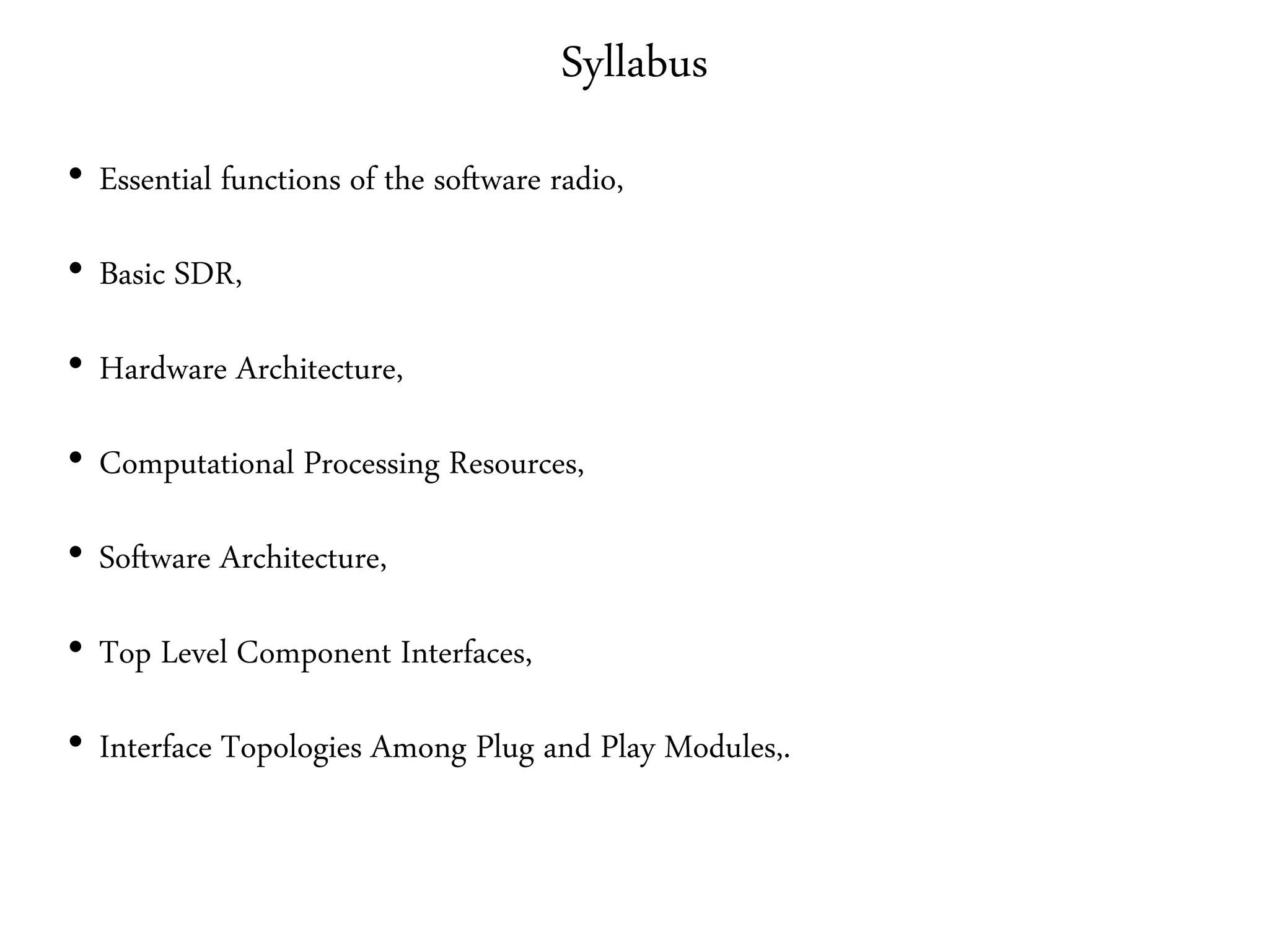
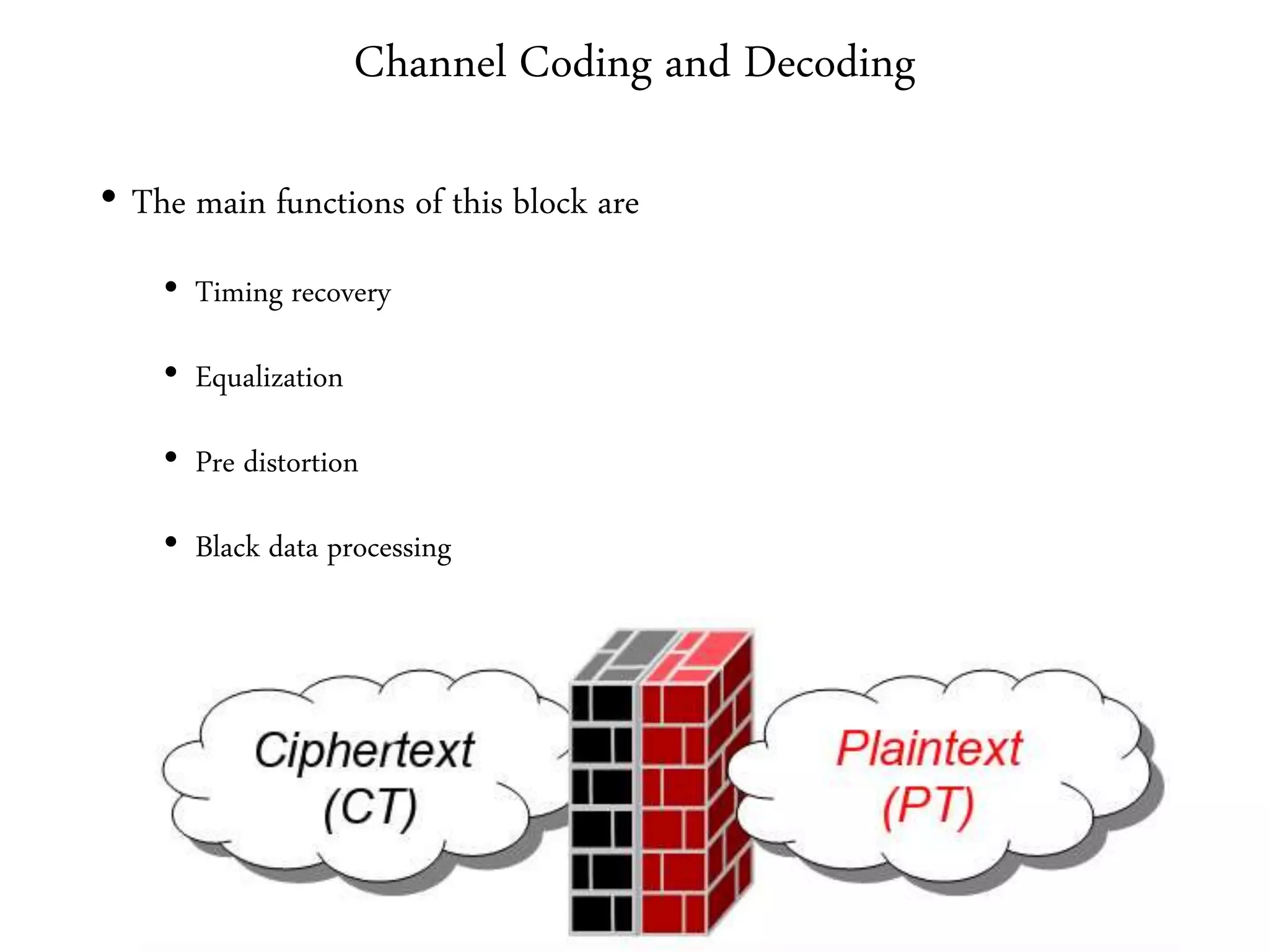
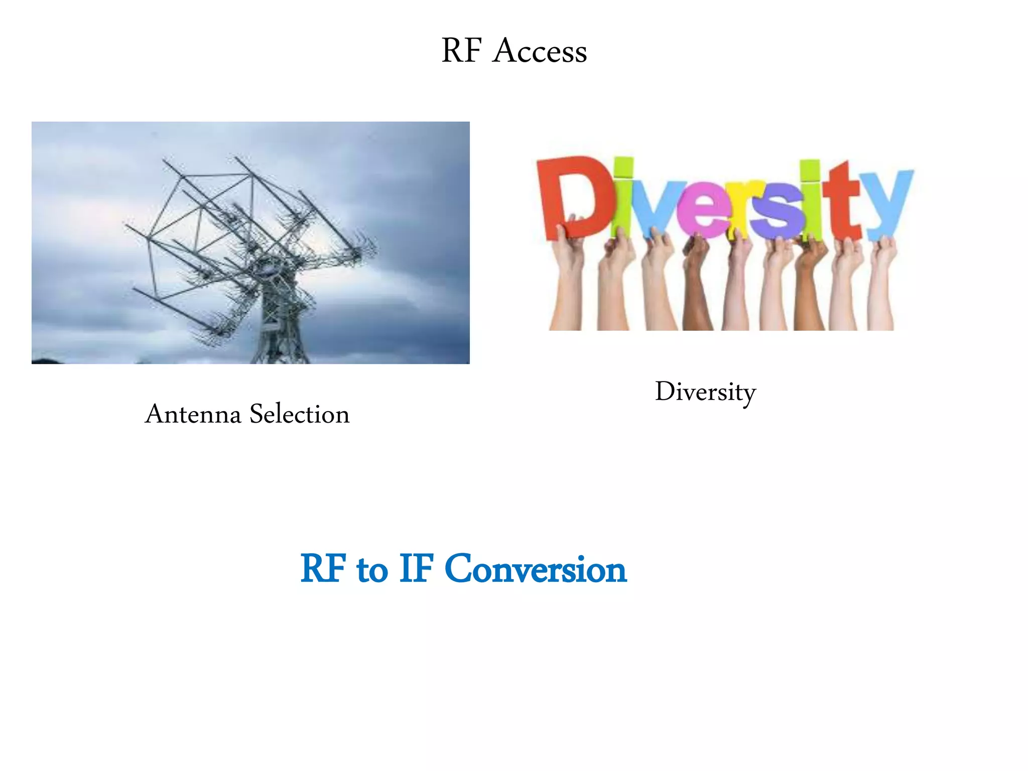
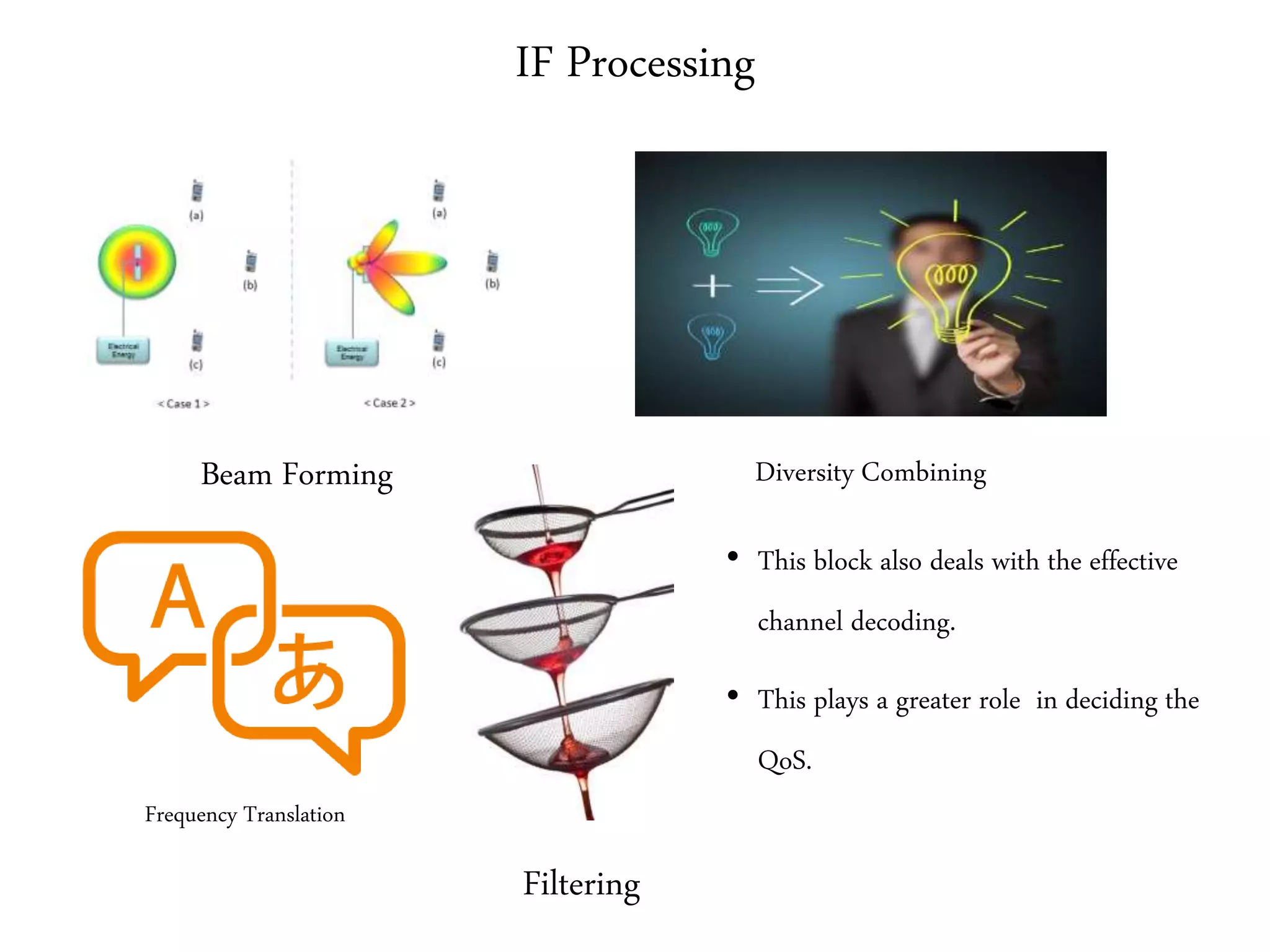
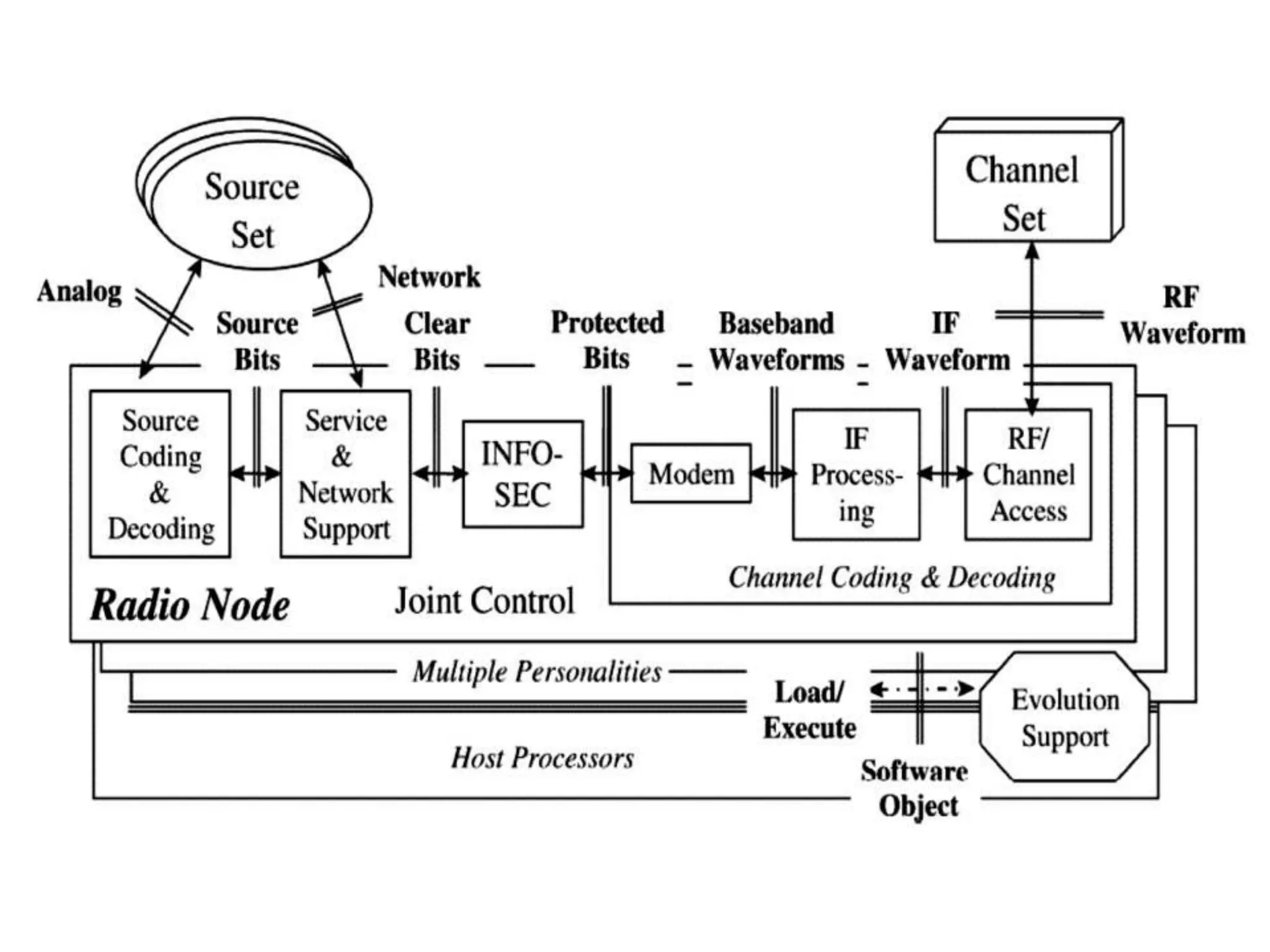


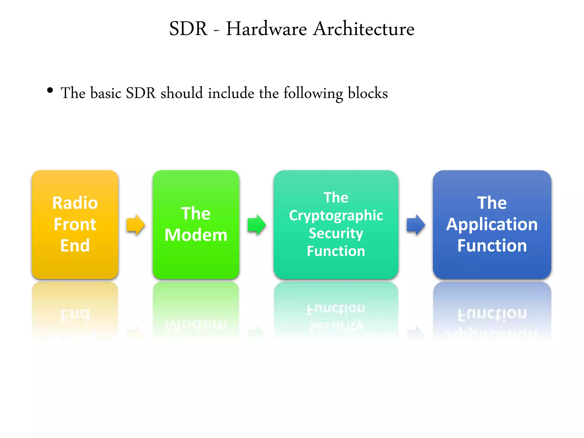


This document provides an overview of the syllabus for the Cognitive Radios course offered by RMK College of Engineering and Technology. It discusses key topics that will be covered including SDR architecture, channel coding and decoding, RF access, IF processing, channel sets, multiple personalities, evolution support, joint control, and top level component interfaces. Standard interfaces in SDR systems are also described such as analog stream, source bit stream, clear bit streams, protected bit stream, IF waveform, RF waveform, and network interface.


![Multiband Transceivers - [Chapter 5] Software-Defined Radios](https://cdn.slidesharecdn.com/ss_thumbnails/ch5-150613070934-lva1-app6892-thumbnail.jpg?width=640&height=640&fit=bounds)