Downloaded 167 times

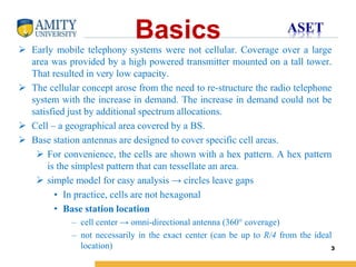
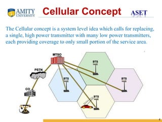
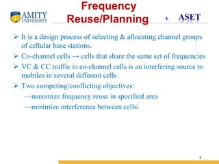
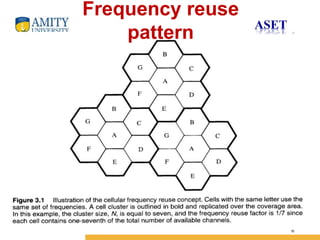
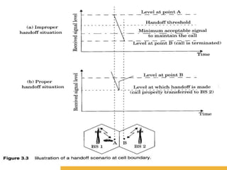
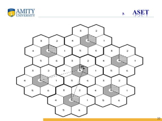


The document discusses key concepts in cellular network design including: 1) The cellular concept divides a large service area into smaller cells served by low-power base stations to improve capacity compared to single transmitter systems. 2) Frequency reuse planning involves assigning different channel groups to neighboring cells to minimize interference while maximizing frequency reuse. 3) Handoff strategies are used to transfer calls between cells as users move, and guard channels and queuing can help reduce dropped calls. 4) Techniques like cell splitting, sectoring, and smaller cell zones can help improve coverage and capacity in congested areas without requiring additional spectrum.