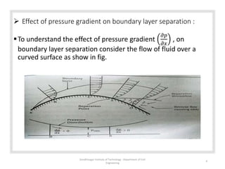
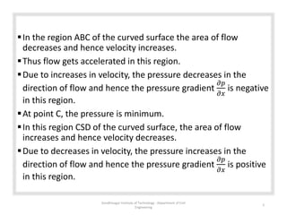
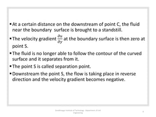
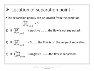
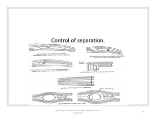
Applied fluid mechanics
Separation of boundary
layer
Gandhinagar Institute Of Technology 1
 Separation of boundary layer :
 As the flow proceeds over a solid surface, the boundary layer
thickness increases.
 The velocity profile changes from parabolic to logarithmic.
 In the boundary layer, the velocity of fluid varies from at the
solid boundary to free stream velocity in the direction
normal to the solid body.
 The fluid layer adjacent to the solid surface has to do work
against surface friction by consuming some kinetic energy.
 This loss of kinetic energy is recovered from the adjacent
fluid layers through momentum exchange process.
 Thus the velocity of the layers goes on decreasing.
Gandhinagar Institute of Technology : Department of Civil
Engineering
2
Along the length of the solid body, at the certain point a stage
may come when the boundary layer may not be able to keep
sticking to the solid body.
In other words, the boundary layer will be separated from the
surface. This phenomenon is called boundary layer separation.
The point on the body at which the boundary layer is on the
verge of separation from the surface is called point of
separation.
Gandhinagar Institute of Technology : Department of Civil
Engineering
3
 Effect of pressure gradient on boundary layer separation :
To understand the effect of pressure gradient
𝜕𝑝
𝜕𝑥
, on
boundary layer separation consider the flow of fluid over a
curved surface as show in fig.
Gandhinagar Institute of Technology : Department of Civil
Engineering
4
In the region ABC of the curved surface the area of flow
decreases and hence velocity increases.
Thus flow gets accelerated in this region.
Due to increases in velocity, the pressure decreases in the
direction of flow and hence the pressure gradient
𝜕𝑝
𝜕𝑥
is negative
in this region.
At point C, the pressure is minimum.
In this region CSD of the curved surface, the area of flow
increases and hence velocity decreases.
Due to decreases in velocity, the pressure increases in the
direction of flow and hence the pressure gradient
𝜕𝑝
𝜕𝑥
is positive
in this region.
Gandhinagar Institute of Technology : Department of Civil
Engineering
5
At a certain distance on the downstream of point C, the fluid
near the boundary surface is brought to a standstill.
The velocity gradient
𝜕𝑢
𝜕𝑦
at the boundary surface is then zero at
point S.
The fluid is no longer able to follow the contour of the curved
surface and it separates from it.
The point S is called separation point.
Downstream the point S, the flow is taking place in reverse
direction and the velocity gradient becomes negative.
Gandhinagar Institute of Technology : Department of Civil
Engineering
6
 Location of separation point :
The separation point S can be located from the condition,
𝜕𝑢
𝜕𝑦 𝑦=0
= 0
1) If
𝜕𝑢
𝜕𝑦 𝑦=0
is positive ……….the flow is not separated.
2) If
𝜕𝑢
𝜕𝑦 𝑦=0
= 0………the flow is on the verge of separation.
3) If
𝜕𝑢
𝜕𝑦 𝑦=0
is negative ……….the flow is separated.
Gandhinagar Institute of Technology : Department of Civil
Engineering
7
 Disadvantages of boundary layer separation :
Separation of the boundary layer greatly affects the flow as a
whole.
In particular formation of a weak zone of disturbed fluid on the
downstream, in which the pressure approximately constant and
much less then that on the upstream, gives the rise to
boundary forces.
Thus, the separation of boundary layer gives rise to additional
resistance to flow.
Gandhinagar Institute of Technology : Department of Civil
Engineering
8
 Methods of controlling separation of boundary layer :
1. Acceleration of the fluid in the boundary layer :
• this method consists of supplying additional energy to the particles of
fluid which are being retarded in the boundary layer.
• This may be achieved by injecting fluid in to the region of boundary layer
from the interior of the body with the help of some suitable device as
show in fig. (a)
• In the other method, additional energy is supplied to the related fluid in
the boundary layer by diverting a portion of the fluid of the main stream
from the region of high pressure through a slot provided in the body as in
the case of the slotted wing as show in fig. (c)
2. Suction of the fluid from the boundary layer :
• In this method the slow moving fluid in the boundary layer is removed by
suction through or through a porous surface as show in fig. (b), so that on
the downstream of the point of suction a new boundary layer start
developing which is able to withstand an adverse pressure gradient and
hence separation is prevented.
Gandhinagar Institute of Technology : Department of Civil
Engineering
9
Gandhinagar Institute of Technology : Department of Civil
Engineering
10
3. Provision of guide vanes as shown in fig. (d) divided the
passage and brings about a well guide flow without
separation and recirculation.
4. in case of diffuser, a small divergence may be provided in the
passage. The semi-angle of a diffuser is limited to 5˚. Fig. (e).
5. The flow over a spherical object may be made to continue
unseparated over a longer distance by installing a trip wire
ring as shown in fig. (f).
Gandhinagar Institute of Technology : Department of Civil
Engineering
11
Gandhinagar Institute of Technology : Department of Civil
Engineering
12

Separation of boundary layer

  • 1.
    Applied fluid mechanics Separationof boundary layer Gandhinagar Institute Of Technology 1
  • 2.
     Separation ofboundary layer :  As the flow proceeds over a solid surface, the boundary layer thickness increases.  The velocity profile changes from parabolic to logarithmic.  In the boundary layer, the velocity of fluid varies from at the solid boundary to free stream velocity in the direction normal to the solid body.  The fluid layer adjacent to the solid surface has to do work against surface friction by consuming some kinetic energy.  This loss of kinetic energy is recovered from the adjacent fluid layers through momentum exchange process.  Thus the velocity of the layers goes on decreasing. Gandhinagar Institute of Technology : Department of Civil Engineering 2
  • 3.
    Along the lengthof the solid body, at the certain point a stage may come when the boundary layer may not be able to keep sticking to the solid body. In other words, the boundary layer will be separated from the surface. This phenomenon is called boundary layer separation. The point on the body at which the boundary layer is on the verge of separation from the surface is called point of separation. Gandhinagar Institute of Technology : Department of Civil Engineering 3
  • 4.
     Effect ofpressure gradient on boundary layer separation : To understand the effect of pressure gradient 𝜕𝑝 𝜕𝑥 , on boundary layer separation consider the flow of fluid over a curved surface as show in fig. Gandhinagar Institute of Technology : Department of Civil Engineering 4
  • 5.
    In the regionABC of the curved surface the area of flow decreases and hence velocity increases. Thus flow gets accelerated in this region. Due to increases in velocity, the pressure decreases in the direction of flow and hence the pressure gradient 𝜕𝑝 𝜕𝑥 is negative in this region. At point C, the pressure is minimum. In this region CSD of the curved surface, the area of flow increases and hence velocity decreases. Due to decreases in velocity, the pressure increases in the direction of flow and hence the pressure gradient 𝜕𝑝 𝜕𝑥 is positive in this region. Gandhinagar Institute of Technology : Department of Civil Engineering 5
  • 6.
    At a certaindistance on the downstream of point C, the fluid near the boundary surface is brought to a standstill. The velocity gradient 𝜕𝑢 𝜕𝑦 at the boundary surface is then zero at point S. The fluid is no longer able to follow the contour of the curved surface and it separates from it. The point S is called separation point. Downstream the point S, the flow is taking place in reverse direction and the velocity gradient becomes negative. Gandhinagar Institute of Technology : Department of Civil Engineering 6
  • 7.
     Location ofseparation point : The separation point S can be located from the condition, 𝜕𝑢 𝜕𝑦 𝑦=0 = 0 1) If 𝜕𝑢 𝜕𝑦 𝑦=0 is positive ……….the flow is not separated. 2) If 𝜕𝑢 𝜕𝑦 𝑦=0 = 0………the flow is on the verge of separation. 3) If 𝜕𝑢 𝜕𝑦 𝑦=0 is negative ……….the flow is separated. Gandhinagar Institute of Technology : Department of Civil Engineering 7
  • 8.
     Disadvantages ofboundary layer separation : Separation of the boundary layer greatly affects the flow as a whole. In particular formation of a weak zone of disturbed fluid on the downstream, in which the pressure approximately constant and much less then that on the upstream, gives the rise to boundary forces. Thus, the separation of boundary layer gives rise to additional resistance to flow. Gandhinagar Institute of Technology : Department of Civil Engineering 8
  • 9.
     Methods ofcontrolling separation of boundary layer : 1. Acceleration of the fluid in the boundary layer : • this method consists of supplying additional energy to the particles of fluid which are being retarded in the boundary layer. • This may be achieved by injecting fluid in to the region of boundary layer from the interior of the body with the help of some suitable device as show in fig. (a) • In the other method, additional energy is supplied to the related fluid in the boundary layer by diverting a portion of the fluid of the main stream from the region of high pressure through a slot provided in the body as in the case of the slotted wing as show in fig. (c) 2. Suction of the fluid from the boundary layer : • In this method the slow moving fluid in the boundary layer is removed by suction through or through a porous surface as show in fig. (b), so that on the downstream of the point of suction a new boundary layer start developing which is able to withstand an adverse pressure gradient and hence separation is prevented. Gandhinagar Institute of Technology : Department of Civil Engineering 9
  • 10.
    Gandhinagar Institute ofTechnology : Department of Civil Engineering 10
  • 11.
    3. Provision ofguide vanes as shown in fig. (d) divided the passage and brings about a well guide flow without separation and recirculation. 4. in case of diffuser, a small divergence may be provided in the passage. The semi-angle of a diffuser is limited to 5˚. Fig. (e). 5. The flow over a spherical object may be made to continue unseparated over a longer distance by installing a trip wire ring as shown in fig. (f). Gandhinagar Institute of Technology : Department of Civil Engineering 11
  • 12.
    Gandhinagar Institute ofTechnology : Department of Civil Engineering 12