Downloaded 2,182 times


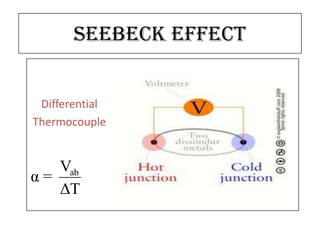

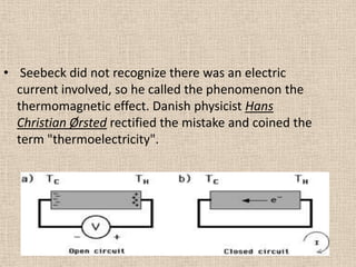


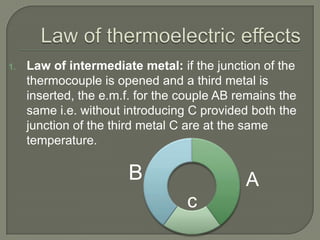

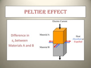
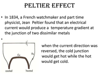


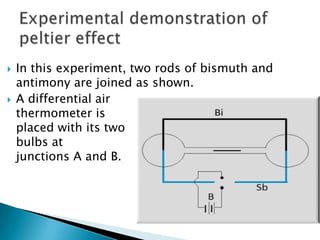
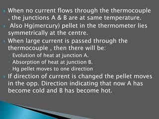


The document summarizes the Seebeck effect and Peltier effect. The Seebeck effect describes how a temperature difference across two dissimilar metals or semiconductors generates an electric current. The Peltier effect is the reverse, where an electric current generates a heat difference at the junction between two materials. Both effects are reversible and form the basis for thermoelectric devices. The Seebeck effect enables applications like thermoelectric generators and thermocouples for temperature measurement. The Peltier effect allows for solid-state refrigeration in devices with no moving parts like Peltier coolers.


