1. SHEEBA SINGH
Principle of operation
Main article: Seebeck effect
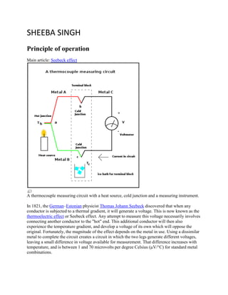
A thermocouple measuring circuit with a heat source, cold junction and a measuring instrument.
In 1821, the German–Estonian physicist Thomas Johann Seebeck discovered that when any
conductor is subjected to a thermal gradient, it will generate a voltage. This is now known as the
thermoelectric effect or Seebeck effect. Any attempt to measure this voltage necessarily involves
connecting another conductor to the "hot" end. This additional conductor will then also
experience the temperature gradient, and develop a voltage of its own which will oppose the
original. Fortunately, the magnitude of the effect depends on the metal in use. Using a dissimilar
metal to complete the circuit creates a circuit in which the two legs generate different voltages,
leaving a small difference in voltage available for measurement. That difference increases with
temperature, and is between 1 and 70 microvolts per degree Celsius (µV/°C) for standard metal
combinations.
2. The voltage is not generated at the junction of the two metals of the thermocouple but rather
along that portion of the length of the two dissimilar metals that is subjected to a temperature
gradient. Because both lengths of dissimilar metals experience the same temperature gradient,
the end result is a measurement of the difference in temperature between the thermocouple
junction and the reference junction.
Derivation from Seebeck effect
Upon heating, the Seebeck effect will initially drive a current. However, provided the junctions
all reach a uniform internal temperature, and provided an ideal voltmeter is used, then the
thermocouple will soon reach an equilibrium where no current will flow anywhere ( ). As
a result, the voltage gradient at any point in the circuit will be given simply by
, where is the Seebeck coefficient at that point, and is the
temperature gradient at that point.
This leads to a characteristic voltage difference independent of many details (the conductors'
size, length do not matter):
where and are the Seebeck coefficients of materials A and B as a function of temperature,
and and are the temperatures of the two junctions. If the Seebeck coefficients are
effectively constant for the measured temperature range, the above formula can be approximated
as:
It is important to note that the emf is not generated at the junctions themselves, but rather in the
wires leading between the hot and cold junctions (where ). As a result, the nature and
composition of the junctions (where is internally constant) itself does not influence the
measured voltage. Conversely, if there are variations in the composition of the wires in the
thermal gradient region (due to contamination, oxidation, etc.), outside the junction, this can lead
to changes in the measured voltage.
Properties of thermocouple circuits
The behavior of thermoelectric junctions with varying temperatures and compositions can be
summarized in three properties:[4]
Homogeneous material—a thermoelectric current cannot be sustained in a circuit of a
single homogeneous material by the application of heat alone, regardless of how it might
vary in cross section. In other words, temperature changes in the wiring between the input
3. and output do not affect the output voltage, provided all wires are made of the same
materials as the thermocouple.
Intermediate materials—the algebraic sum of the thermoelectric EMFs in a circuit
composed of any number of dissimilar materials is zero if all of the junctions are at a
uniform temperature. So if a third metal is inserted in either wire and if the two new
junctions are at the same temperature, there will be no net voltage generated by the new
metal.
Successive or intermediate temperatures—if two dissimilar homogeneous materials
produce thermal EMF1 when the junctions are at T1 and T2 and produce thermal EMF2
when the junctions are at T2 and T3, the EMF generated when the junctions are at T1 and
T3 will be EMF1 + EMF2, provided T1<T2<T3.
Applications
Thermocouples are suitable for measuring over a large temperature range, up to 2300 °C.
Applications include temperature measurement for kilns, gas turbine exhaust, diesel engines, and
other industrial processes. They are less suitable for applications where smaller temperature
differences need to be measured with high accuracy, for example the range 0–100 °C with 0.1 °C
accuracy. For such applications thermistors, silicon bandgap temperature sensors and resistance
temperature detectors are more suitable.
THERMISTER
Thermistor
From Wikipedia, the free encyclopedia
Jump to: navigation, search
Negative temperature coefficient (NTC) thermistor, bead type, insulated wires
A thermistor is a type of resistor whose resistance varies significantly with temperature, more
so than in standard resistors. The word is a portmanteau of thermal and resistor. Thermistors are
4. widely used as inrush current limiters, temperature sensors, self-resetting overcurrent protectors,
and self-regulating heating elements.
Thermistors differ from resistance temperature detectors (RTD) in that the material used in a
thermistor is generally a ceramic or polymer, while RTDs use pure metals. The temperature
response is also different; RTDs are useful over larger temperature ranges, while thermistors
typically achieve a higher precision within a limited temperature range, typically −90 °C to
130 °C.[1]
![The voltage is not generated at the junction of the two metals of the thermocouple but rather
along that portion of the length of the two dissimilar metals that is subjected to a temperature
gradient. Because both lengths of dissimilar metals experience the same temperature gradient,
the end result is a measurement of the difference in temperature between the thermocouple
junction and the reference junction.
Derivation from Seebeck effect
Upon heating, the Seebeck effect will initially drive a current. However, provided the junctions
all reach a uniform internal temperature, and provided an ideal voltmeter is used, then the
thermocouple will soon reach an equilibrium where no current will flow anywhere ( ). As
a result, the voltage gradient at any point in the circuit will be given simply by
, where is the Seebeck coefficient at that point, and is the
temperature gradient at that point.
This leads to a characteristic voltage difference independent of many details (the conductors'
size, length do not matter):
where and are the Seebeck coefficients of materials A and B as a function of temperature,
and and are the temperatures of the two junctions. If the Seebeck coefficients are
effectively constant for the measured temperature range, the above formula can be approximated
as:
It is important to note that the emf is not generated at the junctions themselves, but rather in the
wires leading between the hot and cold junctions (where ). As a result, the nature and
composition of the junctions (where is internally constant) itself does not influence the
measured voltage. Conversely, if there are variations in the composition of the wires in the
thermal gradient region (due to contamination, oxidation, etc.), outside the junction, this can lead
to changes in the measured voltage.
Properties of thermocouple circuits
The behavior of thermoelectric junctions with varying temperatures and compositions can be
summarized in three properties:[4]
Homogeneous material—a thermoelectric current cannot be sustained in a circuit of a
single homogeneous material by the application of heat alone, regardless of how it might
vary in cross section. In other words, temperature changes in the wiring between the input](data:image/gif;base64,R0lGODlhAQABAIAAAAAAAP///yH5BAEAAAAALAAAAAABAAEAAAIBRAA7)