Downloaded 31 times
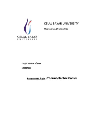
![scientists began studying some of the earlier thermoelectric work in an effort to construct
power generators for use at remote locations throughout the country. This Russian interest in
thermoelectricity eventually caught the attention of the rest of the world and inspired the
development of practical thermoelectric modules. Today‟s thermoelectric refrigerators make
use of modern semi-conductor technology whereby doped semi-conductor material takes the
place of dissimilar metals used in early thermoelectric experiments. [Ref.1]
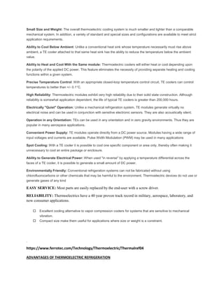
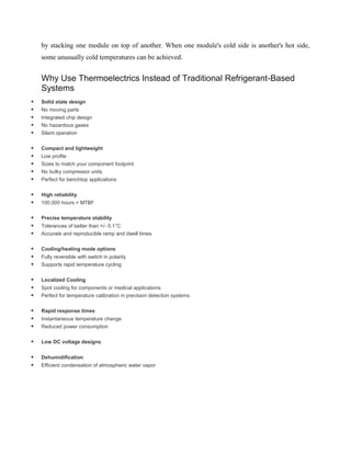
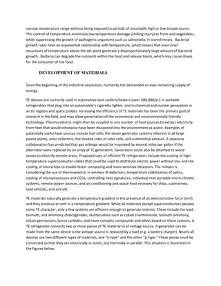
In 1821, Thomas Seebeck discovered that a continuously flowing current is created when two
wires of different materials are joined together and heated at one end.This idea is known as the
Seebeck Effect. The Seebeck effect has two main applications including temperature
measurement and power generation. Thirteen years later Jean Charles Athanase reversed the
flow of electrons in Seebeck.s circuit to create refrigeration. This effect is known as the Peltier
Effect. This idea forms the basis for the Thermoelectric refrigerator.Scottish scientist
WilliamThomson (later Lord Kelvin) discovered in 1854 that if a temperature difference exists
between any two points of a current carrying conductor, heat is either evolved or absorbed
depending upon the material.6 If such a circuit absorbs heat, thenheat may be evolved if the
direction of the current or of the temperature gradient is reversed[1]. The Peltier effect is a
temperature difference created by applying a voltage between two electrodes connected to a
sample of semiconductor material. This phenomenon can be useful when it is necessary to
transfer heat from one medium to another on a small scale. The Peltier effect is one of three
types of thermoelectric effect; the other two are theSeebeck effect and the Thomson effect. In
a Peltier-effect device, the electrodes are typically made of a metal with excellent electrical
conductivity. The semiconductor material between the electrodes creates two junctions
between dissimilar materials, which, in turn, creates a pair of thermocouple voltage is applied
to the electrodes to force electrical current through the semiconductor, thermal energy flows in
the direction of the charge carriers.[2]. In its simplest form, this may be done with a single
semiconductor 'pellet' which is soldered to electrically-conductive material on each end (usually
plated copper). In this 'stripped-down' configuration, the second dissimilar material required
for the Peltier effect, is actually the copper connection paths to the power supply. It is
important to note that the heat will be moved (or 'pumped') in the direction of charge carrier
flow throughout the circuit— actually, it is the charge carriers that transfer the heat.[3].But in
order to pump appreciable amount of heat, we need to interconnect such semiconductor
electrically and thermally parallel. Moreover it needs costly power supply arrangement to
supply high current requirement for parallel arrangement of semiconductor. So semiconductor
can be arranged electrically in series but thermally parallel which further increases the
possibility of short circuiting and reduces the reliability of system. The best optimized way to
connect the semiconductor is in the form of pn junctions which overcome the above
mentioned problems .[Ref.2]](https://image.slidesharecdn.com/thermoelectriccooler-180425145339/85/Thermoelectric-cooler-3-320.jpg)
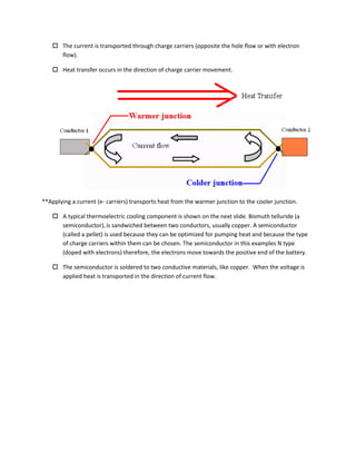
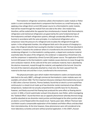
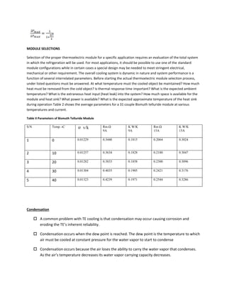
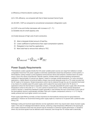
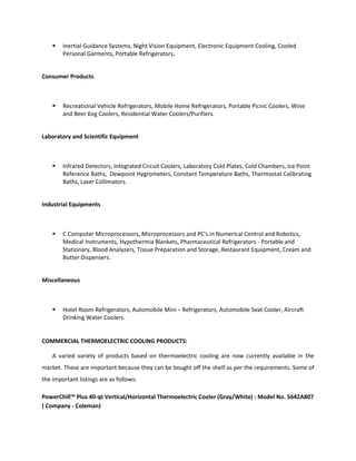
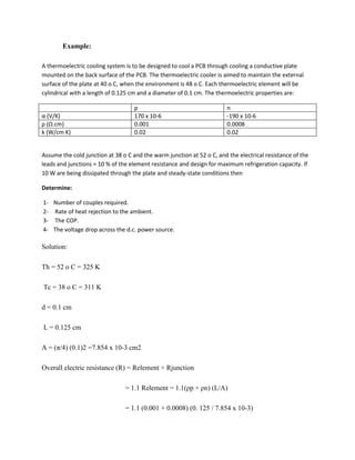
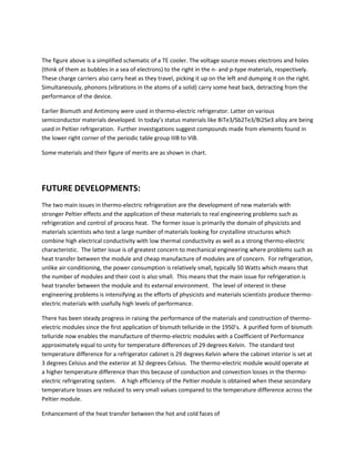
![zT for p-type thermoelectric materials [ref3]
Similar results are shown for n-type semiconductors
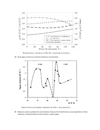
Bi2Te3 Properties
Below is a plot of the figure of merit (Z), Seebeck coefficient, electrical resistivity, and thermal
conductivity, as a function of temperature for Bi2Te3. Carrier concentration will alter the values below.](https://image.slidesharecdn.com/thermoelectriccooler-180425145339/85/Thermoelectric-cooler-14-320.jpg)
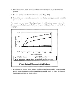
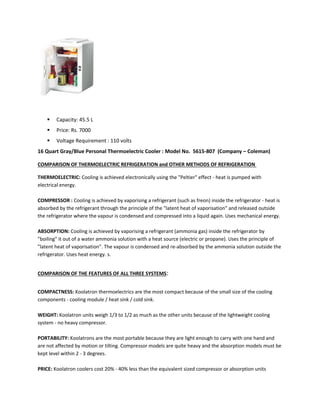
![Although the principle of thermoelectricity dates back to the discovery of the Peltier effect, there was
little practical application of the phenomenon until the middle 1950‟s. Prior to then, the poor thermoelectric
properties of known materials made them unsuitable for use in a practical refrigerating device. According to Nolas
et al [3], from the middle 1950s to the present the major thermoelectric material design approach was that
introduced by A.V. Ioffe, leading to semi-conducting compounds such as Bi2Te3, which is currently used in
thermoelectric refrigerators. In recent years there has been increased interest in the application of thermoelectric
to electronic cooling, accompanied by efforts to improve their performance through the development of new bulk
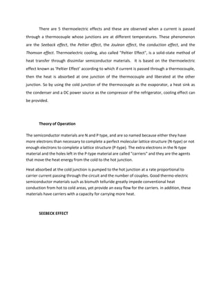
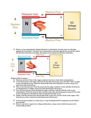
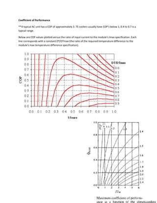
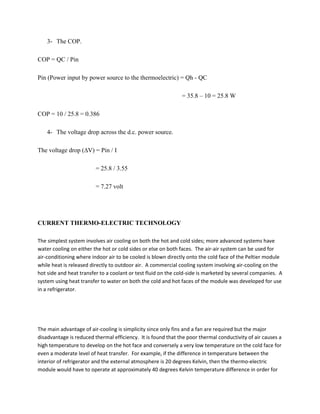
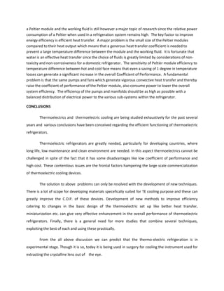
materials and thin film micro coolers [3]. The usefulness of thermoelectric materials for refrigeration is often
characterized by the dimensionless product, ZT, of the thermoelectric figure of merit Z and temperature T. The
expression for the thermoelectric figure of merit is given by:
Where ρ is the electrical resistivity, k is the thermal conductivity, and is the Seebeck Coefficient.
Note: low electrical resistivity and thermal conductivity are required for high high figure of merit. These
values are temperature dependent therefore, the figure of merit is temperature dependent. P and N
type material have different figures of merit and are averaged to determine a materials overall quality.
Fluerial et al [4] reported that in 1991 JPL started abroad search to identify and develop advanced
materials. Among the materials considered, Skutterudite and Zn4Sb3 based materials appeared
particularly promising and several of these materials are being developed. ZT values equal to or greater
than one have been obtained for these materials over different ranges of temperature varying from 375
to 975K. However, to be particularly useful for electronic cooling applications, improvements in ZT are
needed over the temperature range of 300 to 325K or below. Another strategy for enhancing ZT being
pursued by researchers at MIT, Harvard and UCLA focuses on reduced dimensionality as occurs in
quantum wells (2D) or quantum wires.
Table I Figure of Merit for Different Materials
Material Figure of merit
Pb – Te 1.2 x 10⁻³
Pb – Se 1.2 x 10⁻³
k
Z
](https://image.slidesharecdn.com/thermoelectriccooler-180425145339/85/Thermoelectric-cooler-16-320.jpg)
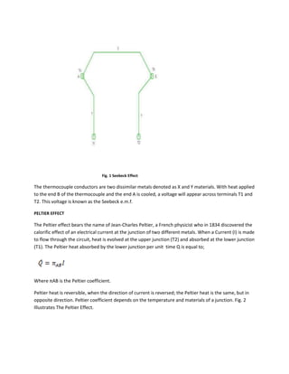
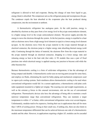
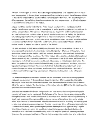
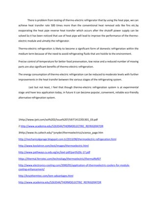
![Pb2 – Te3 1.2 x 10⁻³
Bi2 – Te3 1.3 x 10⁻³
(BiSb)2 – Te3 3.3 x 10⁻³
THERMOELECTRIC REFRIGERATORS COMPENENTS
The thermoelectric refrigerator consists of the following components:
A. The Thermoelectric Module
The thermoelectric module consists of pairs of P-type and N-type semi-conductor thermo element forming
thermocouple which are connected electrically in series and thermally in parallel. The modules are considered to
be highly reliable components due to their solid state construction. For most application they will provide long,
trouble free service. In cooling application, an electrical current is supplied to the module, heat is pumped from
one side to the other, and the result is that one side of the module becomes cold and the other side hot.
B. Heat Sink
The heat sink usually made of aluminum, is in contact with the hot side of a thermoelectric module. When the
positive and negative module leads are connected to the respective positive and negative terminals of a Direct
Current (D.C) power source, heat will be rejected by the module‟s hot side, the heat sink expedites the removal of
heat. Heat sink typically is intermediates stages in the heat removal process whereby heat flows into a heat sink
and then is transferred to an external medium. Common heat sinks include free convection, forced convection and
fluid cooled, depending on the size of the refrigerator.
C. Cold Side
The cold side also made of aluminum is in contact with the cold side of a thermoelectric module, when the positive
and negative module leads are connected to the respective positive and negative terminals of a direct current
(D.C) power source, heat will be absorbed by the module‟s cold side. The hot side of a thermoelectric module is
normally placed in contact with the object being cold.
D. Spacer Block
The spacer block though optional in water chillers is used to ensure sufficient air gap between the heat sink and
the object being cooled.
E. Power Source
Thermoelectric module is a Direct Current (D.C) device. Specified thermoelectric module performance is valid if a
Direct Current (D.C) power supply is used. Actual D.C power supply has a rippled output. This D. C. component is
detrimental [7]. Degradation of thermoelectric module performance due to the ripple can be approximated by:](https://image.slidesharecdn.com/thermoelectriccooler-180425145339/85/Thermoelectric-cooler-17-320.jpg)
![quiet, the presence of an AC ripple signal within the module and wire leads may be unsatisfactory. The acceptable
level of power supply ripple for such applications will have to be determined on a case-by-case basis.
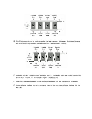
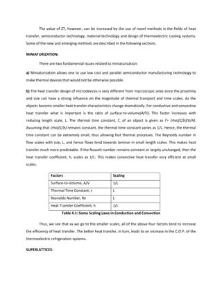
Thermoelectric Performance
TE performance depends on the following factors:
The temperature of the cold and hot sides.
Thermal and electrical conductivities of the device’s materials.
Contact resistance between the TE device and heat source/heat sink.
Thermal resistance of the heat sink.
The current yielding the maximum COP is given by:
The maximum COP is:
Where Tm= (TH+TC)/2
The COP corresponding to the maximum heat pumping capacity is:
The current corresponding to the maximum heat pumping capacity is:
]1)1[(
))((
2/1
m
chnp
ZTR
TT
I
]1)1)[((
]/)1[(
2/1
12
12
2/1
1
max
m
m
in
c
ZTTT
TTZTT
W
Q
cH
cHc
q
TZT
TTZT )(2/1
2
R
T
I
cnp
q
)(
](https://image.slidesharecdn.com/thermoelectriccooler-180425145339/85/Thermoelectric-cooler-23-320.jpg)

![A new approach to increase ZT is to use superlattice structures to reduce k. [5]
In heat conduction, a quantum of vibrational energy is called a phonon, and heat conduction can
be studied as a transport of phonons. To increase ZT, strategies to reduce k and ρ simultaneously have
been very difficult. For example, by making amorphous materials, one can reduce k by introducing many
scattering sites for phonons and thereby reducing l. However, they also scatter electrons and thereby
reduce ρ. Because at the fundamental level, heat conduction by phonons is a wave transport problem,
wave effects are being used to alter heat conduction. One such approach is to fabricate a multi-layer
structure containing extremely thin films of two alternating materials. Such a superlattice should have a
period of 1-10 nm since the wavelength of phonons that dominate in heat conduction fall in this regime.
Phonon wave interference effects in superlattices reduce the propagation speed of phonons and
thereby reduce the effective thermal conductivity. Therefore, as the superlattice period thickness
decreases, thermal resistance increases and the thermal conductivity goes on reducing with increasing
number of such interfaces.
e.g. Using PbTe quantum wells and electron confinement to quantum wells with thickness ranging from
1.7 to 5.5 nm, a factor of 5 increase was found in Z relative to bulk PbTe of the same volume.
Thermal conductivity reduction in this manner is being used in thermoelectric devices to
produce high-performance refrigerators.
Methods like miniaturization and superlattices allow us to manipulate the thermal properties of
materials which can have a strong influence on the performance of thermoelectric refrigeration devices.
Use of PCMs, new materials with unusual electronic and thermal properties and other novel heat
transfer designs significantly increase the C.O.P. of TE devices and thus need to be developed more
vigorously
.
Design Methodology](https://image.slidesharecdn.com/thermoelectriccooler-180425145339/85/Thermoelectric-cooler-27-320.jpg)
![ Laser diodes
Laboratory instruments
Temperature baths
Refrigerators
Telecommunications equipment
Temperature control in missiles and space systems
Heat transport ranges vary from a few milliwatts to several thousand
watts, however, since the efficiency of TE devices are low, smaller heat
transfer applications are more practical.
Commercial devices based on thermoelectric materials have come up in a big way recently. In
addition to the benefits thermoelectrics offer over the conventional devices, commercial factors like
decrease in production costs and significant opening of consumer markets have helped it in a big way
and the use of T.E. devices is increasing day by day.
Thermoelectric cooling is used in medical and pharmaceutical equipment, spectroscopy systems,
various types of detectors, electronic equipment, portable refrigerators, chilled food and
beverage dispensers, and drinking water coolers.
Requiring cooling devices with high reliability that fit into small spaces, powerful integrated
circuits in today's personal computers also employ thermoelectric coolers.
Using solid state heat pumps that utilize the Peltier effect, thermoelectric cooling devices are
also under scrutiny for larger spaces such as passenger compartments of idling aircraft parked at
the gate.
Some of the other potential and current uses of thermoelectric cooling are: [8]
Military/Aerospace](https://image.slidesharecdn.com/thermoelectriccooler-180425145339/85/Thermoelectric-cooler-29-320.jpg)
![available for recreational use.
BATTERY DRAIN: Koolatron coolers have a maximum current drain on 12 volts of 4.5 amps. Compressor
portables draw slightly more current when running but may average slightly less depending on thermostatic
control settings. Absorption portables draw 6.5 to 7.5 amps when running and may average about 5 amps
draw.
BATTERY PROTECTION: Consider the "Battery Saver" option as discussed in the previous section.
COOLING PERFORMANCE: Compressor systems are potentially the most efficient in hot weather. Some
models will perform as a portable freezer and will refrigerate in ambient temperatures of up to 110 degrees
F. Koolatron units will refrigerate in sustained ambient temperatures of up to 95 degrees F. If they are kept
full, they will refrigerate satisfactorily even if peak daytime temperatures reach 110 degrees F because the
contents temperature will lag behind the ambient. The food will be just starting to warm up when the air
cools off in the evening which will bring the food temperature back down to normal. Absorption type
refrigerators provide almost the same cooling performance as Koolatron portables but are less efficient at
high ambients.
FREEZING ICE CUBES: Compressor systems will usually make a quantity of small ice cubes except in very hot
weather. Gas absorption systems can do the same except in hot weather. Koolatron thermoelectric units do
not make ice cubes but can preserve them in a plastic container for 2 - 3 days which is often adequate for
most applications.
SAFETY: Koolatron systems are completely safe because they use no gases or open flames and run on just 12
volts. Compressor systems can leak freon which can be extremely dangerous especially if heated. Absorption
systems may use propane which can be extremely dangerous in the event of a leak.
RELIABILITY: Koolatrons thermoelectric modules do not wear out or deteriorate with use. They have been
used for military and aerospace applications for years because of their reliability and other unique features.
Compressors and their motors are both subject to wear and freon-filled coils are subject to leakage and
costly repairs. Absorption units are somewhat temperamental and may require expert servicing from time to
time, especially if jarred when travelling.
EASE OF SERVICING AND MAINTENANCE: Koolatron units have only one moving part, a small fan (and 12 volt
motor) which can easily be replaced with only a screw driver. Most parts are easily replaced by the end-user.
Compressor and absorption units both require trained (expensive) mechanics and special service equipment
to service them.
Since thermoelectric cooling systems are most often compared to conventional systems,
perhaps the best way to show the differences in the two refrigeration methods is to describe the
systems themselves.[1] A conventional cooling system contains three fundamental parts - the
evaporator, compressor and condenser. The evaporator or cold section is the part where the](https://image.slidesharecdn.com/thermoelectriccooler-180425145339/85/Thermoelectric-cooler-32-320.jpg)
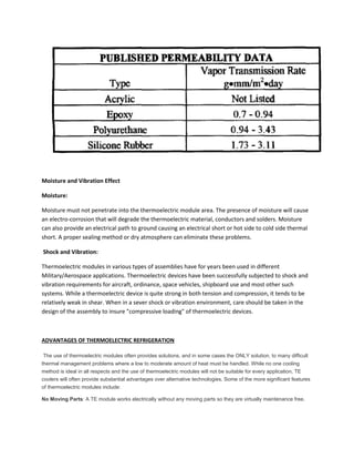
![= 0.0315 Ω
Conduction coefficient (C) = (kp + kn) (A/L)
= (0.02 + 0.02) (7.854 x 10⁻³ /0.125)
= 2.513 x 10⁻³ W/K
Figure of merit (Z) = (αp - αn) 2/ RC
= (360 x 10-6) 2 / (0.0315 x 2.513 x 10-3)
= 1.636 x 10⁻³ K-1
1- Number of couples required.
QC = QC (max) = N C [(Z Tc 2 )/2 – (Th – Tc)] 10
= N (2.513 x 10⁻³) [0.5 (1.636 x 10-3 x (311)2 ) – (14)]
N ≈ 62 couples
2- Rate of heat rejection to the ambient (Qh).
Iopt. = (αp - αn) Tc /R
= (360 x 10-6) x 311/ 0.0315
= 3.55 A
Then
Qh = N [(αp - αn) Th x Iopt – C (Th – Tc) + I2 opt R/2]
= 62 [(360 x 10-6) 325 x 3.55 - 2.513 x 10⁻³ (14) + (3.55)2 0.0315/2]
= 35.8 W](https://image.slidesharecdn.com/thermoelectriccooler-180425145339/85/Thermoelectric-cooler-36-320.jpg)


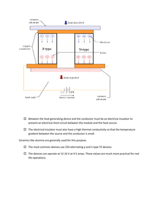
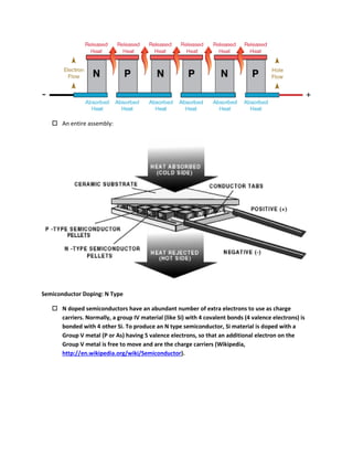
The document discusses thermoelectric cooling, which uses the Peltier effect to create a heat pump-like cooling system without moving parts. It operates by passing a current through two dissimilar conductors joined at two points maintained at different temperatures. When current is applied, heat is absorbed at one junction and expelled at the other, allowing one side to be cooled. Thermoelectric coolers use semiconductors like bismuth telluride in a series of p-n junctions to transfer heat from one side to the other in response to an applied current, providing solid-state cooling without liquids or gases.


