Downloaded 484 times
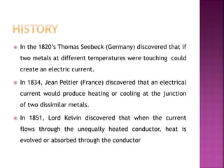
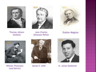
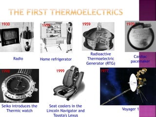
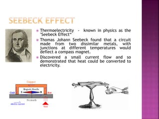
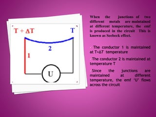
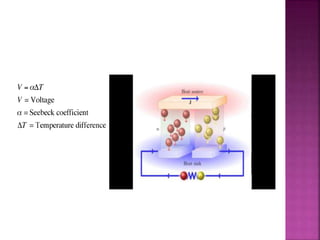

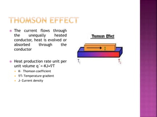

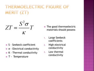
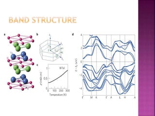
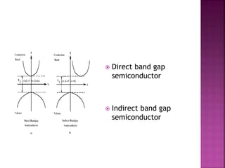
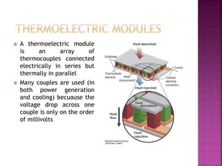
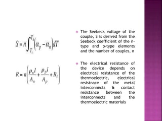
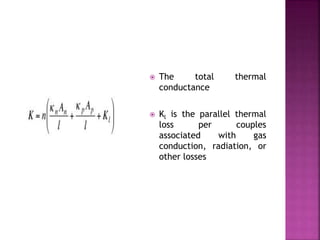
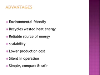
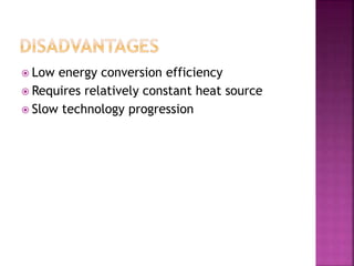


This document summarizes the history and principles of thermoelectricity. It discusses how in the 1820s, Thomas Seebeck discovered that connecting two different metals and maintaining a temperature difference between them produces an electric current, known as the Seebeck effect. Later, Jean Peltier found that applying a current to two metals produces heating or cooling at their junction. In 1851, Lord Kelvin discovered the Thomson effect regarding heat absorption or production based on current direction. The document then explains key concepts in thermoelectric materials like the Seebeck coefficient and figures of merit involving electrical conductivity and thermal conductivity. It also discusses applications of thermoelectric generators and coolers in various technologies.


![Polymer [ बहुलक ] Chemistry Notes PDF - Irfanullah Mehar - JJ Sir Chemistry.pdf](https://cdn.slidesharecdn.com/ss_thumbnails/polymerchemistrynotespdf-irfanullahmehar-jjsirchemistry-260210172118-3f9b37f7-thumbnail.jpg?width=640&height=640&fit=bounds)


