PRESENTED BY:
NISCHITH B S
THIN FILMS
Define Thin Films!
A thin film is a layer of materialranging from fractions of
a nanometer (monolayer) to several micrometers in thickness.
Thin film technology is a "self organizing" structural evolution.
Ex:In ancient times, people already knew how to beat gold into a thin film (<
1 μm thickness) with hammers and knew how use this "gold leaf" for
coating allkinds of stuff.
2
Purpose of Thin Film development!
o To maintain surface uniformity.
o To reduce the amount (or mass) of light absorbing
material.
o Spray Coating Technology for Superior Functional
Medical Coatings.
o To decrease the weight and bulkiness of the
materials.
3
Thin Film Technology
Thin film technology involves deposition of
individual molecules or atoms.
Uniform ultra-thin film coatings onto stents,
catheters, balloons, endoscopic instruments,
pacemakers, heart valves, glucose monitors,
sensors, medical textiles, blood collection tubes,
surgical implants, orthopedic implants, and
diagnostic devices.
Example for industrial thin films produced are:
1. 1.Amorphous Silicon (a-Si)
2. 2.Cadmium Telluride (CdTe)
4
Properties to be considered!
 FILM THICKNESS : The physical properties of a thin
film are highly dependent on their thickness. Thickness
measurement methods are applied during deposition
("in situ") and methods by which the thickness can be
determined after finishing a coating run ("ex situ").
a) Gravimetric Method b) Optical Method
 ROUGHNESS : In Ultrathin Films, it can influence all
film properties such as mechanical, electrical,
magnetical or optical properties. roughness types, the
mechanisms of their origin, roughness measurement
and roughness quantification needs to be taken into
consideration.
5
 CHEMICAL PROPERTIES:
Conventional methods of chemical analysis
as atomic emission, atomic absorption spectral
analysis, X-ray fluorescence and mass
spectrometry play an important role for the
production of the coating materials.
Interaction of photons, electrons, ions or other
particles with the coating or surface has to be
analyzed.
6
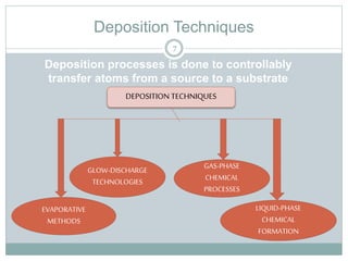
Deposition Techniques
DEPOSITION TECHNIQUES
EVAPORATIVE
METHODS
GLOW-DISCHARGE
TECHNOLOGIES
GAS-PHASE
CHEMICAL
PROCESSES
LIQUID-PHASE
CHEMICAL
FORMATION
7
Deposition processes is done to controllably
transfer atoms from a source to a substrate
Chemical Vapour Deposition(CVD)
Gaseous compounds react to form a
dense layer on a heated substrate.
The most widely deposited wear-
resistant coatings are TiC, TiN,
chromium carbide and alumina.
Deposition temperatures are
generally in the range 800-1000C.
Thicknesses are limited to about
10mm due to the thermal expansion
mismatch stresses which develop on
cooling which also restrict the coating
of sharp edged components.
Advantages
 High coating hardness
 Good adhesion (if the coating is not
too thick)
 Good throwing power (i.e.
uniformity of coating)
Disadvantages
 High temperature process (distortion)
 Sharp edge coating is difficult (thermal
expansion mismatch stresses)
 Limited range of materials can be coated
 Environmental concerns about process
gases
8
Physical Vapour Deposition (PVD)
Advantages
 Excellent process control
 Low deposition temperature
 Dense, adherent coatings
 Elemental, alloy and compound
coatings possible
Disadvantages
 Vacuum processes with high
capital cost
 Limited component size treatable
 Relatively low coating rates
 Poor throwing power without
manipulation of components
Low pressure coating processes in
which the coating flux is produced by
a physical process. There are two
main types:-
1. Evaporation
2. Sputtering
 In both cases the source material is a
solid (metal or ceramic). A reactive
gas may be used in the deposition
chamber to deposit compound
coatings from an elemental source or
maintain the stoichiometry of
coatings from compound sources,
though thinner layers are used in
microelectronics and thicker layers
are used for high temperature .
9
Ultrasonic Nozzle Technology
Low velocity, soft spray with minimal overspray
saves up to 80% in coating material
Independent control of process parameters
including flow rate, spray velocity, drop size and
deposition
 Precise control over a wide range of flow rates
 Non-clogging, repeatable performance
Choice of drop size depending on nozzle
frequency (drop sizes range from 18 - 49
microns)
 Deagglomeration of particles in suspension due
to ultrasonic vibration
10
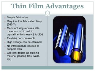
Thin Film Advantages
o Simple fabrication
o Requires low fabrication temp
(300 C)
o Manufacturing requires little
materials. -thin cell to
crystalline thickness= 1 to 300
o Flexible/ non-breakable
o High voltage can be obtained
o No infrastructure needed to
support cells
o Cell can double as building
material (roofing tiles, walls,
etc)
11
Where can we apply it ??
 Thin-filmBatteries: Thin-filmprintingtechnologyis beingused to
apply solid-statelithiumpolymers to a variety of substrates to
create uniquebatteries for specialized applications. Thin-film
batteries can be deposited directly onto chips or chip packages in
any shape or size. Flexiblebatteries can be made by printing
onto plastic, thinmetalfoil, or paper.
12
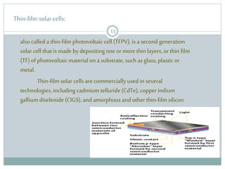
Thin-film solar cells:
alsocalleda thin-film photovoltaic cell (TFPV), is a second generation
solar cell that is made by depositing one or more thin layers,or thin film
(TF)ofphotovoltaic materialona substrate, such as glass, plastic or
metal.
Thin-film solar cellsare commerciallyused in several
technologies, including cadmium telluride(CdTe), copper indium
galliumdiselenide (CIGS),and amorphousandother thin-film silicon
13
Blood Collection Tubes
Targeted coating of side walls, layering of
chemistries, polymers, or clotting agents.
Common materials sprayed include Heparin,
Silicone and EDTA.
Nozzle design allows atomizing surface
to reach inner diameter lengths. Fully
automated control of electronics. Custom
multiple nozzle systems for high volume
production. Soft, low velocity spray will not
collect on base of tubes.
14
Orthopedic Implants
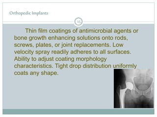
Thin film coatings of antimicrobial agents or
bone growth enhancing solutions onto rods,
screws, plates, or joint replacements. Low
velocity spray readily adheres to all surfaces.
Ability to adjust coating morphology
characteristics. Tight drop distribution uniformly
coats any shape.
15
Micro
encapsulation
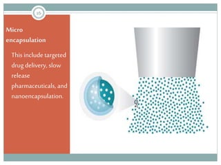
This include targeted
drug delivery, slow
release
pharmaceuticals, and
nanoencapsulation.
16
http://electrical-engineering-portal.com/solar-energy-expands-escapes-the-power-grid
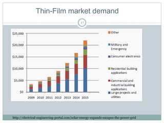
Thin-Film market demand
17
Future of Thin Films
18
Natures solution to thin film cells.
Developing molecules out of organic compounds
like carbon and hydrogen
Super-thin film about 100 nanometers thick, can
be applied as a paint.
Replaces heavy metals currently being used in
cells. Creates a biodegradable, almost natural cell.
References
 Barna, P. B. (2005). HISTORY OF THIN FILMS. In P. B. Barna, HISTORY OF
THIN FILMS (p. 37). Budapest, Hungary: Research Institute for
Technical Physics and Materials Science of HAS.
 IFP TUWEIN. (2009, September 30). Retrieved from
http://static.ifp.tuwien.ac.at:
http://static.ifp.tuwien.ac.at/homepages/Personen/duenne_schichten/pdf
/t_p_dschapter1.pdf
 Jiang, P. D. (2008). Introduction to Thin Film Technology. LOT , 28.
 Ohring, M. (2001). Materials Science of Thin Films . Boston: Academic
Press.
 Seshan, K., & McGuire, G. (2002). HANDBOOK OF THIN-FILM DEPOSITION
PROCESSES. Norwich, New York, U.S.A.: NOYES PUBLICATIONS.
 (2007, October). Retrieved from en.wikipedia.org:
http://en.wikipedia.org/wiki/Thin_film
19
20